ZIMO MX82E User manual

Operating Instructions
ACCESSORY DECODER MX82E, MX82D, MX82V
ACCESSORY DECODER MX82 Page 1
CONTENT:Page
1. Introduction 2
2. Specifications 2
3. Addresses und Programing 3
4. Connecting the MX82 to
track or power bus 8
5. Connecting the MX82 to accessories 8
6. Operating accessories 9
7. Position recognition and feedback 10
Using the MX82 with other DCC systems 10
EDITION:
2004 04 15
2004 05 10
2004 08 25
NOTE:
ZIMO decoders containan EPROM which stores software that determines its characteristics and functions.
The software version can be read out inCV #7.
The current version may not yet be capable of all thefunctions mentioned in this manual.
Such missingorincomplete functions can be installedlater by updating the software or replacing the
EPROM (only at the factory).
Beginning in October 2004, all decoders(MX82 with SW-version 3 and up) can be updated by the end user;
seepage 3.
Software updates are available for the end user free of charge (except forthe purchase of the programming
tool).
Updates and alterations performed by Zimo are not covered by any warranty.
The warranty covers hardware damage exclusively, provided such damageis not caused by the useror the
connected equipment.
For update service see www.zimo.at !
Incomplete or not yet imple-
mented features
(up to Software-Version 3):
- LED communication
- Back-EMF
- Position feedback without
end switches
- Bi-directional communication
SW -Version 3: User updatable decoder MX82E, MX82D, MX82V

1. Introduction
The MX82 accessory decoders operate turnouts, signals, decouplers etc.
accordingtothestandardized NMRA-DCCdataformat.Theycanbeused
with any NMRA-DCC system.
Accessory decoders are connected either to the track or a 2-conductor
power bus coming from the command station. The rather small size of the
MX82 (especially the MX82E) allows the decoder to be installed inside the
road bed of HO
track or switch motor housings (e.g. LGB turnouts).
Turnouts and signals connected to anaccessory decodercan be operated
either:
?withacab/throttle(e.g.ZIMOMX2,MX2FU,MX21,MX21FU,MX3etc.)
?using decoder inputs (from track contact/switches)
?with computer and appropriate software (STP-dispatching software)
2. Specifications
Thedecoderisbuiltona.75x.39”board.TheMX82EandMX82Vareinsulatedinathin
shrink tube, while the MX82D is wrapped in a slightly heavier shrink tube and sealed
with a special sealer on each end.
T E C H N I C A L D A T A :
Track voltage (fromtrack or power bus) .................................................12 - 24 V
Accessory output - time-limited current (turnouts) .......................................... 3 A
Accessory output - continuous current (signals) ............................................. 1 A
“On-time” for turnouts ...................................................................... 0,1 to 15 sec
Stand-by power (outputs off) ..................................................................... 10 mA
Operating temperature ................................................. 4 to 212 F (-20 to 100oC)
Dimensions .............. MX82E 78x.43x.12” (20x11x3mm) MX82D 86x.47x.13”
(22 x 12 x 3,5 mm) MX82V 78x.43x.16” (20 x 11 x 4 mm)
SW-Version 3 and up: UPDATE SOFTWARE ON PROGRAMMING TRACK ......
Beginningwithproduction dateSeptember/October2004, Zimo decoders are
equipped to handle a software update by the end user. That requires a Zimo
MXDECUPdecoderupdatemodule(availableinNovember2004)aswellas
acomputerwithWindowsoperatingsystemandInternetconnection(fordown-
loading the new softwarefrom Zimo’s web site).The update module is not tied
toaZimosystemandcanthereforebeusedwithotherDCC systemsaswell!
Decoders manufactured earlier(before SW-version 3) will have to be sent to Zimofor a one-time upgrade.
Subsequent updates can then be performed by the user. This upgrade will be offered at a veryreasonable
priced service in October 2004. The decoder software can be read out with CV #519.
For more information about decoder update and the update module, please
checkourwebsite:www.zimo.atand/orfuture editionsofthisinstruction man-
ual (October 2004 and up).
Page 2ACCESSORY DECODER MX82
MX82 Top View
Track
Turnout
Turnout
Track
+ - supply
red
orange
blue
grey
black
(+)
MX82E
Controls one turnout with solenoid, motor or EPL drive. The
shallow construction simplifies the installation in turnout
housings. BEMF controlled motor drive. Additional inputs to
either operate 4 servos or for train-actuated turnouts or other
switches.
Position feedback through ZIMO train number recognition
pulses (same as MX81) or the standardized NMRA
bi-directional communication *)
MX82D Identical to MX82E but sealed against water intrusion.
MX82V A “doubled-up” MX82E .78x .43x.19in (20 x 11 x 5 mm). 2
turnouts or 4 signal light bulbs/LED’s (also 4 Servos
additionally) - bargain priced per turnout.

OVERLOAD PROTECTION:
As is the case with all ZIMO decoders, the outputs of the MX82 are protected
againstexcessivecurrentdraw andshortcircuits.Anyoutputisturned offifanover
-
load situation exists. After that, the decoder keeps testing the affected output,
which often results in flashing lights.
Eventhough thedecoder iswellprotected, do notassume thatitisindestructible.Pleasepayat-
tention to the following:
Faultydecoder connection;connecting themotorleadsto trackpowerfor instance oranoverlooked
connectionbetweenthemotor brushesandrail pick-up’scausesshortsthatare notalwaysrecognized
by theoverloadprotectioncircuitandcouldleadtomotor endstage damageoreven totaldestruction of
the decoder.
Unfit ordefectivemotors; a shortedwindingor commutatoris notalwaysrecognized by the high cur-
rentconsumption it causes, because these are often just short spikes. They can lead to decoder
damage, including damage to end stages due to long time exposure.
Voltagespikes whichcanbeinduced frommotorsandotherloadsconnected toadecodermaybe
responsible formore decoder damage thanexcessive current draw. Theheight of suchvoltagespikes
depends on the trackvoltage selected and can reach several hundred volts. They will be removedby
specialovervoltageprotection circuits butthecapacityandspeed ofsuchelementsislimited. Don’tse-
lecta higher trackvoltagethan whatisrecommendedfor therolling stockused on the layout. The full
range (up to 24V), adjustable with a Zimocommandstation, should only be utilized in special cases.
Even though Zimodecoderscan be operated at 24 Volts (MX62 at 20V), thatis not thecase if used in
conjunctionwith some other function elements built into a locomotive.
THERMAL PROTECTION:
Alldecoderscoveredinthismanualhave theability tomeasure theirownoperating
temperature. Power to the motor will be turned off once the temperature of the
decoderexceeds 100oC. The headlights start flashing rapidly, atabout 10 Hz, so
that theoperator can recognize this state. Motor control willresumeautomatically
after a drop in temperature of about 20oC, typically in 30 to 60 seconds.
3. Addresses and Programming
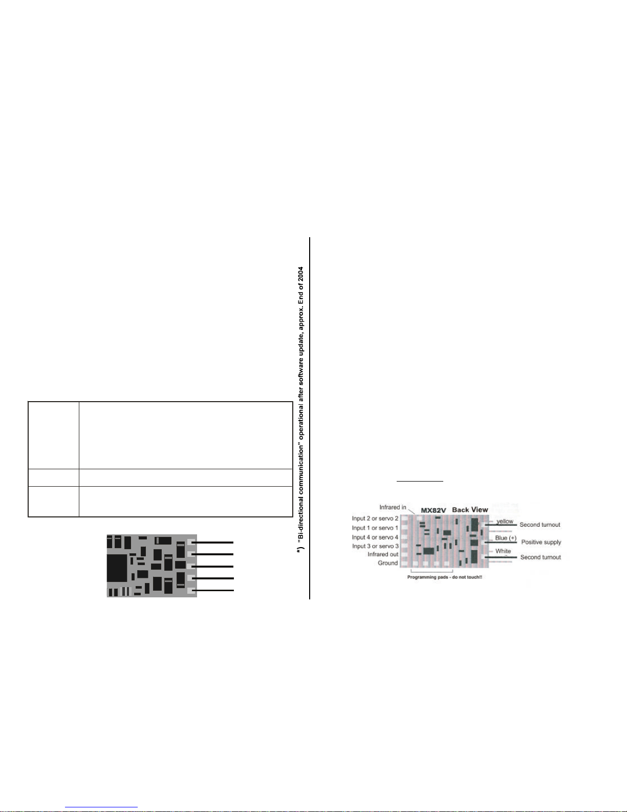
Incontrastto locodecoders,accessorydecoders require not only anaddress but
also asubaddress (2 sub addresses for theMX82V).The address is required for
decoder access with a cab, and the sub address determines with which function
key the turnout will be operated..
Althoughthe MX82maybeinstalled immediately, anaddresshas tobe assignedbefore itiscon-
nected to the layout wiring!
Assigning a new address is not possiblewithseveral MX82 connected in parallel to the track or
power bus; if tried, all MX82 would receive the same address.
PROGRAMMING PROCEDURES:
Detailed procedures (service mode and operational mode) for program-
mingandreadingofaddressesandconfigurationvariablesarefoundinthe
instruction manual for the cab (e.g. MX21).
Programming is even simpler and more convenient with the help of a computer and ADaPT
software (E.Sperrer, software developer)!
Technical note to acknowledgment/read-out during “service mode” programming:
Whenprogrammingadecoderwithacaborcomputer,everysuccessfulprogrammingstepwillbemade
visiblebythedecoder.Thesameacknowledgmentmethodisusedwhenreadingtheconfigurationvari-
ables.
The decoder acknowledgment is carried out by briefly turning the motor and headlights on, causing
shortpowerpulsesthatthecommandstationrecognizes.Acknowledgmentandread-out ofadecoderis
onlysuccessful ifthecurrentconsumption is high enough, which means that the motor and headlights
have to be connected or at least one of the two.
The meaning of Configuration Variables (CV’s) are in part standardized by the
NMRA DCC RECOMMENDED PRACTICES, RP-9.2.2. There are however
certainCV’sthatareforZimo decoders only, insomecasesexclusivelyfor specific
types.
Always use the specifications for the decoder in question, since the value range
may differbetween manufacturers, even with standardizedCV’s; inthiscase use
the table below.
ACCESSORY DECODER MX82 Page 3
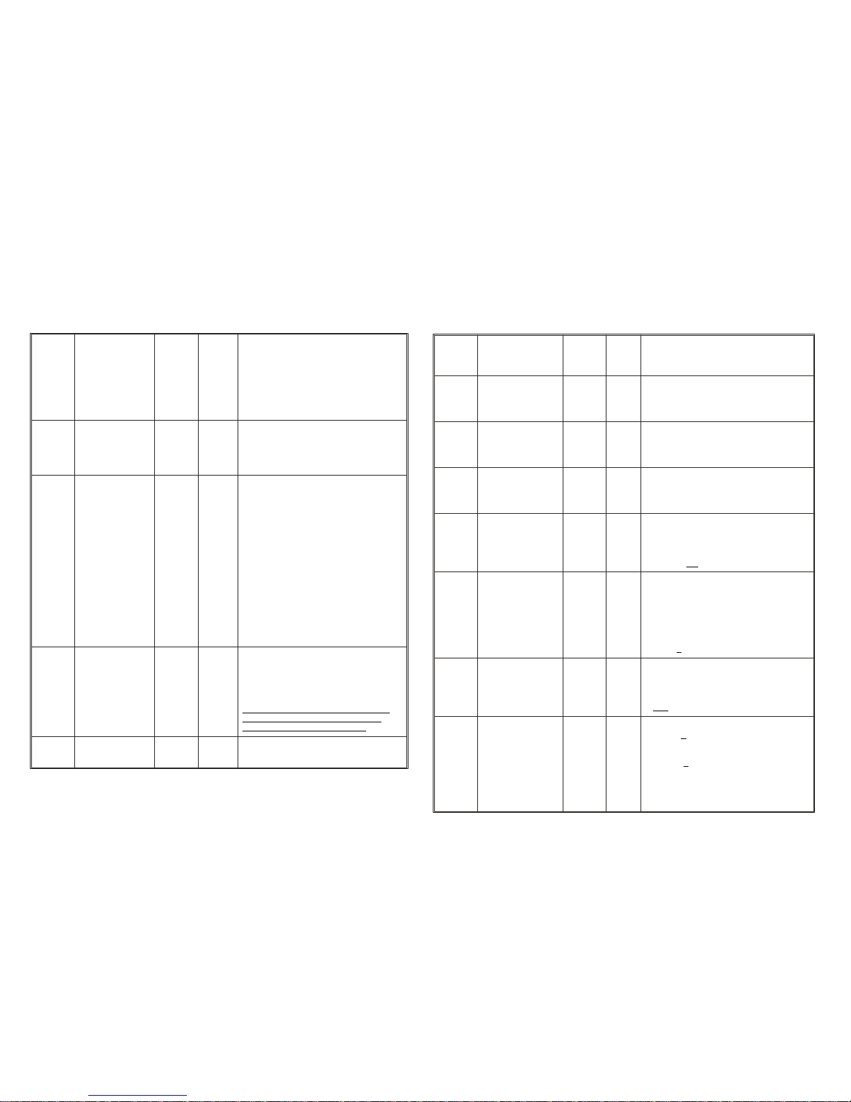
Programming in
“Service mode” ”Operations mode”
Decoder or turnout with decoder on Decoder connected to main track.
programming track (socket: ”PROG”).
Addresses and CV programming. Programming of configuration variables only.
Secure programming with Programming without acknowledgement (commands
are sent repeatedly, which increases reliability)
Read-out of configuration variables and Read-out of configuration variables is not possible.
address is possible. (Later possible with “bi-directional communication”).
Start procedure with “E” and “MAN” keys. Start procedure with “E” and “F” or “E” und “W”.
(”on-the-main”, MX1 -socket ”SCHIENE”),
acknowledgement.

Page 4ACCESSORY DECODER MX82
# 513
# 521
resp.:
# 1, # 9
Decoder address 1- 511 3
The accessory decoder address is spread
over two configuration variables (long 9
bit); the calculation is done by the Zimo
cab; the user enters and reads the
complete address as a number between 1
and 511.
NOTE: A sub address is necessary to
operatea decoder(s).
# 514
resp.:
# 2 Turnout operated
by switch inputs 0
Enter value or combination thereof:
1=Input 1 activated, left
2=Input 2 activated, right
4=Input 3 activated, left (MX82V only)
8=Input 4 activated, right(MX82V only)
# 545
resp.:
# 33
Sub address(es)
For outputs on
top side
(all MX82 types)
and
For outputs on
bottom side
(MX82V only)
MX82E,
MX82D:
0 - 3, 9
MX82V:
0 - 32,
99
Onesand
tensdigit
mustbeof
different
value!!!
10
(For
MX82E
= “0”)
Sub address(es); determine with which
of the 4 function keys, F1 - F4, the
accessory is actuated.
ONES DIGIT: (for top outputs on MX82E
and MX82D )
= 0: F0 (#1 with Zimo cab)
= 1: F1 (#2 with Zimo cab)
= 2: F2 (#3 with Zimo cab)
= 3: F3 (#4 with Zimo cab)
= 9: Top outputs turned off.
TENSDIGIT:(forbottomoutputs, MX82V
only):
= 0: F0 (#1 with Zimo cab)
= 1: F1 (#2 with Zimo cab)
= 2: F2 (#3 with Zimo cab)
= 3: F3 (#4 with Zimo cab)
= 9: bottom outputs turned off.
# 515
# 516
# 517
# 518
resp.:
# 3 to
# 6
Power-on time 0 - 255 2
The time an accessory is powered up
in 1/10 of a second (max. 25 sec.
Default value “2” = 0.2 sec).
Value = 0: continuous on (usually for signal
lights).
These CV’s are tied to sub addresses in
CV #545. Max. 2 of these can be set.
E.g. #515 for F0, #516 for F1 etc.
# 519
resp.:
# 7 Software version Read only This CV displays decoder software
version.
CV-Number Name Value range Description
Default value
# 541
resp.:
# 29 Identification Read
only Identifies the decoder as accessory
decoder.
# 546
resp.:
# 34
Light-up time
(only when “continuous
on” is selected, as in CV
# 515,516, 517or 518= 0)
0 - 255 10 For prototypical signal operation:
Time in 1/10 of a second for a total range
of 25 seconds until the light bulb reaches
its full intensity.
# 547
resp.:
# 35
Light-up delay
(only when “continuous
on” is selected, as in CV
# 515,516, 517or 518= 0)
0 - 255 0For prototypical signal operation:
Time in 1/10 of a second for a total
range of 25 seconds until the light bulb
starts to illuminate.
# 548
resp.:
# 36
Dimming time
(only when “continuous
on” is selected, as in CV
# 515,516, 517or 518= 0)
0 - 255 10 For prototypical signal operation:
Time in 1/10 of a second for a total range
of 25 seconds until the light bulb is
completely off.
# 549
resp.:
# 37
Initial pulse
(except for “continuous
on”) 0 - 255 0
Time in 1/10 of a second for a total range
of 25 seconds until a switch command is
sent after booting up the system or after
connecting a MX82.
Value= 0: No initial pulse.
# 550
resp.:
# 38 Direction
left - right 0- 63 0
Value=1: for top outputs
Value=2: for bottom outputs
(MX82 only)
Value=4: Servo 1, reverses direction
Value=8: Servo 2, reverses direction
Value=16: Servo 3, reverses direction
Value=32: Servo 4, reverses direction
Value= 0: no change in direction
# 551
resp.:
# 39
Dimming
(only when “continuous
on” is selected, as in CV
# 515,516, 517or 518= 0)
0 - 255 255
When output is activated, brightness of
bulb is controlled by pulse with modulation
after “light-up” phase. The larger the value,
the brighter the bulb.
= 255: full brightness
# 552
resp.:
# 40
Single (lights) or
paired (turnout)
functions
and
Position recognition
(on/off)
0 - 7 0
Bit 0: for top outputs
Values = 0: paired function
= 1: single function
Bit 1: for bottom outputs (MX82V only)
Values = 0: paired function
= 2: single function
Bit 2: for position recognition
Values = 0: off
= 4: on

ACCESSORY DECODER MX82 Page 5
# 553
resp.:
# 41
Address and sub
addresses for
Servo output
1 and 2
0 - 33
or
100 -
133
110
This CV determines whether the servos are
controlled with the same address as in CV
# 513, 521 or the next one higher
(default!!!) and which of the 4function keys
F0 - F3 are used.
ONES DIGIT values (for Servo 1):
=0: F0 (#1 with Zimo cab)
= 1: F1 (#2 with Zimo cab)
= 2: F2 (#3 with Zimo cab)
=3: F3 (#4 with Zimo cab)
TENSDIGIT values(for Servo 2):
= 0: F0 (#1 with Zimo cab)
=1: F1 ....... continue as above.
HUNDREDS DIGIT values:
=0 Address as per CV # 513, 521
= 1The servos operate on the next
higher address, that is: address as
in CV # 513,521 + 1.
# 554
resp.:
# 42
Address and sub
addresses for
Servo output
3 und 4
0 - 33
or
100 -
133
132
Use as CV # 553 above but for
servo outputs 3 and 4.
ONES DIGIT for servo 3;
TENS DIGIT for servo 4;
HUNDREDS DIGIT:
= 0 Address as per CV # 513, 521
= 1The servos operate on the next
higheraddress,thatis:address
as in CV # 513,521 + 1.
# 555
resp.:
# 43
Motor acceleration
(with pulse width
modulation, only if CV
#515,516, 517or 518 >0) 0 - 255 0Slow acceleration of motor drive;
time in 1/10 of a second (max. 25 sec) until
the motor connected reaches its full speed
(according to CV #557).
# 556
resp.:
# 44
Motor deceleration
(with pulse width modula-
tion, only if CV #515, 516,
517 or 518 > 0) 0 - 255 0Slow deceleration of motor drive;time in
1/10ofa second (max. 25 sec) untilthemotor
comes to a complete stop.
# 557
bzw.:
# 45
Motor speed
(with pulse width modula-
tion, only if CV #515, 516,
517 or 518 > 0) 0 - 255 255
Maximum motor speed (after acceleration
phase) by means of pulse width modula
-
tion.
= 255: highest possible speed.
# 558
bzw.:
# 46 Back-EMF
0 - 255
(Version 3
and
above)
0Severity of motor control
= 0: no back-EMF
# 561
resp.:
# 49 Servo protocol 0= 0: Servo protocol with positive pulses.
= 1: Servo protocol with negative pulses.
# 562
resp.:
# 50
Servo 1
Left stop 0 - 255 0Determines left stop position.
# 563
resp.:
# 51
Servo 1
Right stop 0 - 255 255 Determines right stop position.
# 564
resp.:
# 52
Servo 1
Rotating speed 0 - 255 30
The entered value represents the time (in 1/10
sec) needed to drive the servo betweendefined
stops. Maximum 25 sec. Default value “30” = 3
sec (plus acceleration and deceleration times
programmed in CV #565).
# 565
resp.:
# 53
Servo 1
Acceleration and
deceleration 0 - 255 20 Slow acceleration and deceleration of servo;
timein1/10ofasec.(max.25sec),defaultvalue
“20” = 2 sec.
# 566 as above,
#567 for
#568 Servo2
# 569
resp.:
# 54
# 55
# 56
# 57
#570 asabove
# 571 for
#572 Servo3
# 573
resp.:
# 58
# 59
# 60
# 61
# 574 as above
# 575 for
# 576 Servo 4
# 577
resp.:
# 62
# 63
# 64
# 65

TIPS and EXAMPLES of using CONFIGURATION VARIABLES:
In regards to wiring: see chapter 5 !
BASIC APPLICATIONS FOR TURNOUTS....
and also semaphores with solenoid or motor drives
Asdelivered(orafter aHARDRESET,which is accomplishedwithaZIMOcab by
changing theprogrammed addressto“0"orbyprogrammingCV#8to8),themost
importantCV’saresetasfollows:MainaddressCV#513,521=3,SubaddressCV
# 545 = 10, Power-on time CV’s # 515 - 518 = 2.
In case of an MX82E or MX82D (1 turnout only):
the turnout connected to the orange, grey and blue wires is operated withthe F0
key (with Zimo cab use key #1) at address #3. Power is supplied for 0.2 seconds,
which is common for solenoid or EPL drives.
With an MX82V for (2 turnouts):
for the firstturnout see above description of the MX82E; the second turnout con-
nectedto the yellow, white andblue wires, isoperatedwiththe F1 key (becauseof
the tens digit set in CV #545=10), with Zimo cab use Key #2.
If amotorizedswitchmachineisused instead of asolenoid or EPL drive asabo-
ve,thepower-ontimehastobechangedaccordingly(CV#515,ifsubaddress“0”is
usedinCV#545).Forexample,iftheturnoutmotor’sswitchtimeis 3seconds,ava-
lue of “30” or somewhat higher should be entered.
TheCV #515isonlythenapplicable ifthesubaddress “0”isused inCV#545.Forsubaddress“1”
useCV #516, forsub address“2” use CV #517 and for sub address “3” use CV #518 to set po-
wer-on time.
Thereasonforthis strangeclassificationisthat theprogrammingissimplerwhen severalaccessoryde-
codersareusedatthesameaddressbutwithdifferentsubaddresses.Insuchacase,eachdecoderhas
its own CVforpower-on time (e.g.oneuses #515, thenext #516 and so on) andthere is no chance that
another decoder gets re-programmed unintentionally.
If 2 motorized switch machines are used with an MX82V, both applicable po
-
wer-onCV’s(e.g.#515and516)havetobeset toanappropriatevalue(e.g.“30”).
Inorder toutilize the4 subaddresses,which areavailable foreachaccessoryde-
coderaddress,several MX82decoder(2MX82Vor4MX82E)havetobeprogram-
medtothesameaddress(inCV#513,521)butdifferentsubaddresses(CV#545).
For example:
-FirstDecoder-MX82E: CV#513,521=25; CV#545=0(default“10”isalsoOK)
-SecondDecoder-MX82V:CV#513,521=25; CV#545=21(that issubaddr1&2)
-ThirdDecoder-MX82E: CV#513,521=25; CV#545=03(thatissubaddress 3)
The power-on times for this example - if different from the default setting of 0.1
seconds- are set as follows:
For the first decoder CV #515 = ...,
For the second decoder CV #516 = ... and CV #517 = ...,
For the third decoder CV #518 = ....
Forced turnout switching using inputs 1 to 4:
Thisisusefulifatrainshouldswitcha turnoutbyitselfwiththehelpofa“switchtrack”,
reed switch etc.
Theinputchannelshavetobe activatedwithCV #514;for theabove example (Inputs
1und 2) CV #514 = 3 would be thecorrectsetting.The turnout can still be controlled
with the cab or a computer (except during activation through the input channels).
Special input function: Applying a permanent positive voltage prevents the turnout
from being switched!
NOTE: Because the same connections are used for servos or switch inputs, itisnot
possible to employ forced switching for servos.
Page 6ACCESSORY DECODER MX82
MX82 back side
Input 2
1Input
Input 4
Input 3
Ground
blue (+)
Pull-down resistors 10K
Turnout
orange
grey
Motor
Switch inputs
To track or other power supply
red
black

SIGNALS . . .
The MX82 is most often used forsimple red/green signals (2 aspect sig
-
nals),which represents the same logic as for a turnout. The MX8 or MX88
would be the better, more economical choice for multi aspect signals.
ThereisonlyonedifferencewhatCV’sareconcernedcomparedtoturnouts
thepower-on timehastobe set to “0”,forcontinuous power. Ofcourse,the
same relationshipapplies between the subaddressand theapplicable CV
(#515 for sub address 0, #516 for sub address 1 and so on).
Often a prototypical slow signal illumination and dimming function is
desired.TheCV#546,547and548canbeusedtoachievethis;typicalval-
uesmaybe:CV#546 =15,CV#547=10andCV#548=15.Thosevalues
are applicable to all lights connected (up to 4 with an MX82V). There is no
relationship between these CV’s and the sub address in contrast to the
“power-on” time (CV # 515-518).
If the paired function of light bulbs (2 with MX82E or 4 with MX82V) is not
possible or desiredand therefore each bulb controlled individually,set
theappropriateBitinCV#552to“1”(onesdigitfortheorange/greyandtens
digit for yellow/white wires). Naturally, the user interface (cab, command
station...) may need tobe configuredaccordingly so that single light bulbs
can be controlled with ease.
ELECTRO MAGNETIC DECOUPLERS . . .
Adecoupleristreatedasasinglefunction.IncaseofanMX82E,CV#552is
setto1andincaseofanMX82Vto11.Mixedoperationisalsopossiblewith
theMX82V(orange/greywiresforaturnout;yellow/whitefordecoupler).
SERVOS . . .
4 logic level outputs (solder pads) are provided for the control of servos
(MX82E as well as MX82V). Each of those outputs can be connected to a
standardservocontrolinput. Thepowerfor theservo(5V) isnotgenerated
by the MX82; another source is required (see chapter 5).
An MX82 can, if so desired, operate up to 4 servos simultaneously with
solenoid or motorized turnouts (or signals) or exclusively.
Attention:
The 4 servo connections are set to the next higher address by default
throughtheCV settings#553=110and #554=132: theservos donot oper
-
ate with the accessory address stored in CV #513 and 521 but rather ac-
cordingtothevaluesinCV#513and#521+1.Forexample:Ifaddress36is
selected, the servos operate at address 37 and Function keys F0, F1, F2
and F3.
Ifyouwish tooperate theservos with the basicaddress as in CV #513,521
(address 36 in this example), the CV’s should be programmed to CV
#553=10and#554=32(omittingthehundredthdigitinbothCV’s=basicad-
dress) and #545=99 (important! This turns off the “usual” outputs for turn-
outs).
INFORMATION WILL BESUPPLEMENTEDLATER (List ofaddress combina-
tions and other experiences with servo drives).
SPECIAL FUNCTIONS for MOTO DRIVES (Switch machines). . .
INFORMATION WILL BE SUPPLEMENTED LATER!
Theoptional“InitialPulse”(CV#549)istoassurethatallturnoutswillbein
the sameposition afterthelayoutis booted up, astheywere before the lay
-
outwasturnedoff.Ifallpulsesweresenttoallturnoutsatthesametime,the
powersupply couldbeoverloaded. Toprevent this,differentvalues canbe
entered toCV #549which spreads thisload over a wider time frame, up to
15 seconds.
Forcontinuouspoweroutput(mostlysignallightbulbs),CV#515(or516,
517, 518 dependingon sub address) has to be set to “0”. Inthis mode the
option of slow illumination and dimming is also available (CV #546, 547,
548), which is an especially prototypical way of signal operation.
Changing CV#550, Bit 0 (Deactivation ofturnoutposition feedback)issel-
dom required.This possibility is there in case somebody is sensitive to the
noisegeneratedbytheturnoutpositionrecognitionfunctionbutalso(rather
unlikely but not impossible if used with other systems) in cases where the
feedbackpulsescouldinterferewiththecommandstationorboosters(e.g.
TrackpowerturnedoffduetoshortcircuitindicationordistortedDCCdata).
ACCESSORY DECODER MX82 Page 7

4. Connecting the MX82 to the track or a power bus
Theaccessory decoder MX82 is connected with thered andblack wireto
thetrackorthepowerbuscomingfrom the commandstationstrackoutput.
Polarityisirrelevant.Anynumberofaccessorydecodersmaybeconnected
in parallel since their own power consumption is extremely low.
NOTE: Connecting the accessory decoder to the track is only practical if the track section con-
cerned is connected itself directly to the command station or booster.
Anaccessorydecoder mustnot be connected to a section of track that is connected to a track section
module with occupancydetection because the small current consumption will cause the tracksection
module to indicate an occupied track that in reality is not true.
5. Connecting the MX82 to accessories
DOUBLE COIL SWITCH MACHINES AND SIGNALS:
Such accessories are connected with 3 wires.
Thebluewiresuppliesthepowerandisconnected
tothecommonwireoftheturnoutandthegreyand
orange wires are connected to the single wires.
MOTORIZED SWITCH MACHINES AND SIGNALS:
Such units are connected with 2 wires. The blue
wire is not needed in this application. The other
wires(grey/orange) areconnectedwith theswitch
machine. The power-on time has to be pro-
grammed with CV #515, 516, 517 depending on
the sub address used.
EPL SWITCH MACHINES (LGB):
EPL switch machines are electrically identical to the
motorized switch machine (see above). The default
power on time of .2 seconds can be left as is since the
actualswitchtimeoftheEPLmachineisrathershort.
SIGNALS:
Commercially available signals have a common wire
that connect to the blue wire (positive) of the decoder.
The single wires are connected with the orange and
grey wire.
Pay attention to polarity in case of LED’s (only signals
with common anode) and use an appropriate resistor
(usually 1Kohm).
Page 8ACCESSORY DECODER MX82
SIGNAL
Red bulb green bulb
grey
orange
blue
+
TWIN COIL SWITCH MACHINE
left coil right coil
grey
orange
blue
MOTORIZED OREPL SWITCH
MACHINE
M
grey
orange
COMMAND
STATION
MX1 MX82 MX82 MX82
black,
red
blue
grey
orange
black
red
Common positive for accessories
with 3 wires
Right turnout connection
Left turnout connection
Track
Track
MX82 Top View

SERVOS:
Most servos sold today require power from a
regulated 5V power supply. This is usually
accomplished with a LM7805 voltage regulator
or equivalent. Additionally, a diode and a couple of
condensers are also needed.
Normally such a power
supply can be fed
through the blue wire
coming from the
decoders internal
regulator, as shown
in this drawing.
However, if the peak
current draw of the
servo exceeds 1 amp,
an external rectifier
connected directly to the track should be used instead (Important: Make
sure that all ground points (decoder, servo and regulator) are connected
with each other!).
Thecontrolwirebetweenthedecoderand theservoshouldnotcontainany
electronic components, such as protective or pull-up resistors!
External power supply for twin coil switch machines
In some applications the track voltage may not be suitable for operating
turnouts. The problem may be caused by too low of a track voltage or a
switch machine that is designed to work on AC only. N gauge switch
machinesfromArnoldandsomeofRoco’sarewellknownforthisproblem.
A possible solution may be found
- inusingapowersupplythatsuppliesanunfilteredDCvoltage(itseffectis
similar to AC and meets the “natural” requirements of many such
machines). For example, an old-fashioned ( non-electronic) model
railroadpowerpackmaybeused.Butpay attentionthatonlytheDCoutput
is suitable. Under no circumstances should the AC output be used !
Anordinarytransformer(e.g.16-18Voutput)witharectifieraddedcan
also be used instead of a model railroad power pack.
- Thepositivewireofthissupplyisconnectedtothecommonwireofthe
twincoil machine.Theothercoilwiresareasusualconnected tothegrey
and orange wire of the MX82. The ground wire of the external power
supply must be connected to the system ground (spade terminal
“MASSE” of the MX1 command station).
6. Operating accessories
. . . with a MX2, MX2FU, MX21or MX21FUcab:
EntertheMX82addressandactivatewithkeys“W” or“A”(the”A”keycan
beusedifthisaddresswasalreadyusedasaccessoryaddressinthepast).
The display is illuminated red, as it always is when the accessory mode is
active.
An additional reminder is the “W” in the display.
See instruction manual for the Zimo cab, MX2, MX21 etc.!
. . . W it h a c o m p u t e r :
See “STP” instruction manual !
ACCESSORY DECODER MX82 Page 9
orange (MX82)
grey(MX82)
To common wire
External
Power
Supply
+
-
TWIN COIL MACHINE
To GROUND at command station
(spade terminal “MASSE” at MX1
MX82 Back View
Servo 2
Servo 1
Servo 4
Servo 3
Ground
blue (+)
7805
1N4007
100 uF,
25 V 100 uF,
25 V
5 V 0 V
Servo control wire
Servo

7. Position recognition and feedback
TheaccessorydecoderMX82isequippedwithafeedbackmechanismthat
is based on the ZIMOtrain number recognition. “Switchpulses” are sent to
thetrackifswitchmachines with endswitches are used,from which anap
-
propriately equipped commandstation is able to learn theturnout position
and subsequently send that info along to the cab and computer.
However, thenecessary hardwarefor the MX1commandstationaswellas
the software were not available at the timethis instruction manual went to
print.It is not clear at this point either whether the turnout position will be
checked only after the turnout is operated or a permanent supervision is
possibleasisthecasewiththeMX8accessorymodule(sothatamanualin
-
tervention is also recognized).
Using the MX82 with other DCC systems
BecausetheMX82accessorydecoder isfullyNMRA-DCC compatible,it
canbeused onlayoutsoperatedbyothercompatible systemsaswell.This
is the case, among others, with “Digital plus” (Lenz) and Digitrax.
MX82 with
Lenz“DIGITALplus”Software-Version2.0ornewer:
With this system number 1 - 255 can be used to operate turnouts. These
numbers are arranged to addresses and sub addresses as follows:
Turnouts 1 - 4 at the LENZ cab: MX82-address 1, Sub address 0 - 3
Turnouts 5 - 8 at the LENZ cab: MX82-address 2, Sub address 0 - 3
Turnouts 9 - 12 at the LENZ cab: Address 3 (DEFAULT !), Sub address
0 - 3 and so on.
If,forexample,anMX82istobeoperatedwith number10,thevaluefortheaddress
in CV #1 must be “3” and the value for the sub address in CV #33 must be “1”.
IftheMX82servooutputsareused,notethattheseareassignedbydefault
to the next higher address than the programmed decoder address.
For example:
Servo outputs at the LENZ cab are controlled with
13 - 16, with a programmed MX82 address 3 (default)
17 - 20, with a programmed MX82 address 4
and so on.
To be able to program a decoder, enter the programming mode, then
the CV mode with the cab. Possible error messages (”Err 2”) due to
missing acknowledgments (which depends on the accessory connected
to the MX82) can be ignored.
MX82 with
LGB:
Hereaswell,turnoutsarenotarrangedinaddressesandsubaddressesbut
rathernumbered;practicallythesameaswiththeLenzsystem(seeabove).
Select theaccessory mode at the 55015 Universal Handy withkeys Fand
1. The turnout address starts at 1, where:
Turnout 1: CV1=1, CV33=0
Turnout 2: CV1=1, CV33=1
Turnout 3: CV1=1, CV33=2
Turnout 4: CV1=1, CV33=3
Turnout 5: CV1=2, CV33=0
Turnout 6: CV1=2, CV33=1
etc.
Switch turnouts with left and right arrow keys.
MX82 with
Intellibox :
IntelliboxalsonumberstheturnoutsliketheLenzsystemdoes(seeabove).
Page 10 ACCESSORY DECODER MX82
This manual suits for next models
2
Table of contents
Other ZIMO Media Converter manuals