Ebyte ECAN-401 User manual

Chengdu Ebyte Electronic Technology Co.,Ltd. ECAN-401 User Manual
Copyright ©2012–2022,Chengdu Ebyte Electronic Technology Co.,Ltd.
2
CONTENTS
1. PRODUCT OVERVIEW......................................................................................................................................................................... 4
1.1 BRIEF INTRODUCTION..................................................................................................................................................................... 4
1.2 FEATURE.............................................................................................................................................................................................. 4
1.3 APPLICATION...................................................................................................................................................................................... 5
2. PRODUCT SPECIFICATIONS AND CHARACTERISTICS................................................................................................................6
2.1 BASIC PARAMETERS.......................................................................................................................................................6
2.2 FACTORY DEFAULT PARAMETERS................................................................................................................................... 6
3. HARDWARE PARAMETER DESIGN INTRODUCTION................................................................................................................... 7
3.1 DESIGN INTRODUCTION................................................................................................................................................. 7
3.2 DIMENSIONS.................................................................................................................................................................. 8
3.3 CONNECTION METHOD...................................................................................................................................................9
3.3.1 RS485 connection method......................................................................................................................................
9
3.3.2 RS422 connection method......................................................................................................................................
9
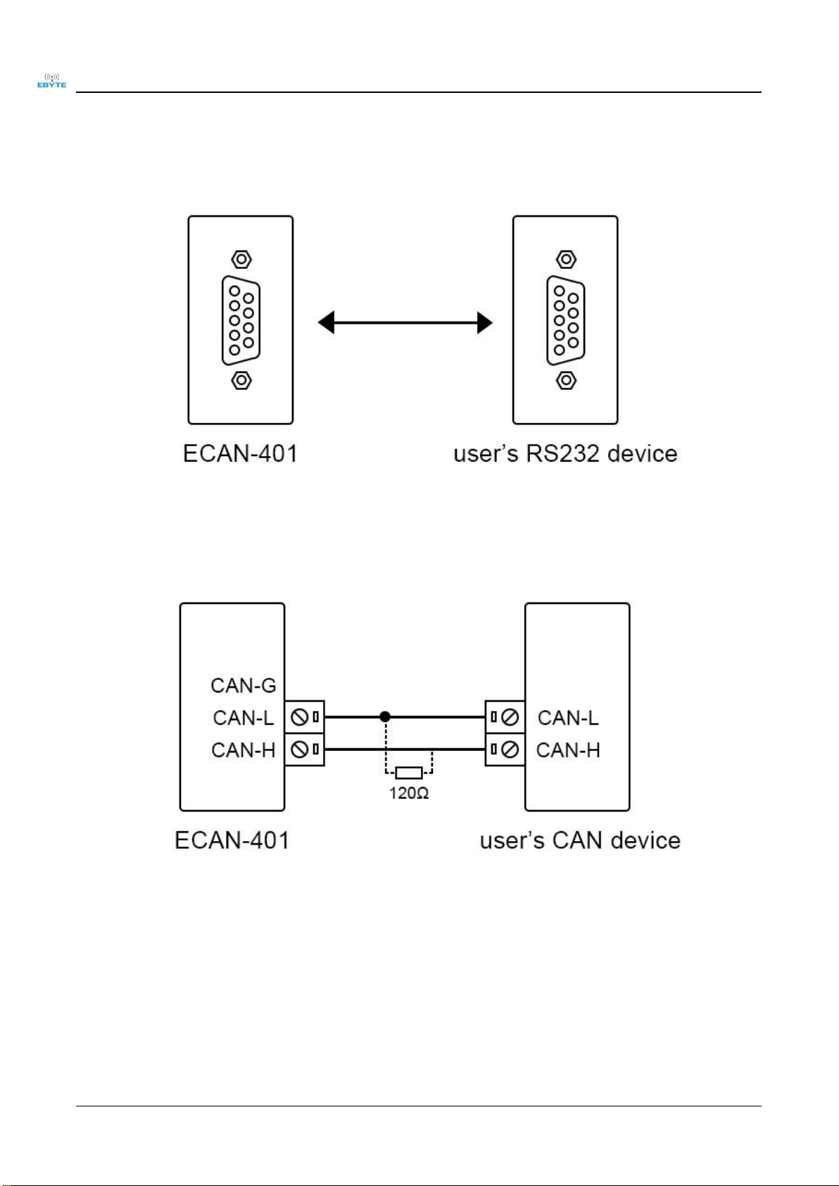
3.3.3 RS232 connection method....................................................................................................................................
10
3.3.4 CAN connection method.......................................................................................................................................
10
4. MODE DESCRIPTION......................................................................................................................................................................... 11
4.1 DATA CONVERSION METHOD........................................................................................................................................11
4.1.1 Transparent conversion mode..............................................................................................................................
11
4.1.2 Transparent transmission with logo mode...........................................................................................................
14
4.1.3 Protocol mode......................................................................................................................................................
16
4.1.4 Modbus mode.......................................................................................................................................................
18
4.1.5 Custom protocol mode..........................................................................................................................................
20
5. AT COMMAND.....................................................................................................................................................................................23
5.1 ENTER AT COMMAND.................................................................................................................................................. 23
5.2 EXIT AT COMMAND..................................................................................................................................................... 23
5.3 QUERY VERSION.......................................................................................................................................................... 24
5.4 RESTORE DEFAULT PARAMETERS................................................................................................................................. 24
5.5 ECHO SETTINGS........................................................................................................................................................... 24
5.6 SERIAL PORT PARAMETERS.......................................................................................................................................... 25
5.7 SETTING/QUERYING CAN INFORMATION.................................................................................................................... 26
5.8 SETTING/QUERYING MODULE CONVERSION MODE....................................................................................................26
5.9 SET/QUERY THE FILTERING MODE OF THE CAN BUS...................................................................................................27
5.10 SET/QUERY FRAME HEADER AND FRAME END DATA..................................................................................................27
5.11 SETTING/QUERYING IDENTIFICATION PARAMETERS.................................................................................................. 27
5.12 SETTING/QUERYING IDENTIFICATION PARAMETERS..................................................................................................28
5.13 SET/QUERY TRANSMISSION DIRECTION......................................................................................................................28
5.14 SETTING/QUERYING FILTER PARAMETERS................................................................................................................ 29
5.15 DELETE THE FILTER PARAMETERS THAT HAVE BEEN SET........................................................................................... 29
6. REVISION HISTORY........................................................................................................................................................................... 30
ABOUT US................................................................................................................................................................................................30

Chengdu Ebyte Electronic Technology Co.,Ltd. ECAN-401 User Manual
Copyright ©2012–2022,Chengdu Ebyte Electronic Technology Co.,Ltd.
3
Disclaimer
EBYTE reserves all rights to this document and the information contained herein.
Products, names, logos and designs described herein may in whole or in part be
subject to intellectual property rights. Reproduction, use, modification or disclosure to
third parties of this document or any part thereof without the express permission of
EBYTE is strictly prohibited.
The information contained herein is provided “as is” and EBYTE assumes no
liability for the use of the information. No warranty, either express or implied, is given,
including but not limited, with respect to the accuracy, correctness, reliability and
fitness for a particular purpose of the information. This document may be revised by
EBYTE at any time. For most recent documents, visit www.ebyte.com.
Note:
The contents of this manual are subject to change due to product version upgrades
or other reasons.Chengdu Ebyte Electronic Technology Co.,Ltd. reserves the right to
make changes to the contents of this manual without notice or suggestion.This manual
serves only as a user guide and Chengdu Ebyte Electronic Technology Co.,Ltd.
endeavours to provide accurate information in this manual, but Chengdu Billionaire
Electronics Co., Ltd. does not ensure that the contents are completely error-free and
that all statements, information and suggestions in this manual do not constitute any
express or implied warranty.

Chengdu Ebyte Electronic Technology Co.,Ltd. ECAN-401 User Manual
Copyright ©2012–2022,Chengdu Ebyte Electronic Technology Co.,Ltd.
4
1. Product Overview
1.1 Brief Introduction
ECAN-401 is a small intelligent protocol conversion product independently developed by Chengdu Ebyte
Electronic Technology Co., Ltd. The product uses 8V ~28V wide voltage power supply,
integrates 1 CAN-BUS interface, 1 RS485 interface, 1 RS232 interface and 1 RS422
interface, which can realize two-way conversion between CAN and RS485/RS232/RS422
different protocol data. The product supports serial AT command configuration and host
computer configuration device parameters and working modes, and supports five data
conversion modes including transparent conversion, transparent conversion with logo,
protocol conversion, Modbus RTU conversion, and user-defined (user). At the same time,
ECAN-401 intelligent protocol converter has the characteristics of small size, easy
installation, and high protection isolation design for CAN interface. It has a very high cost performance in the
development of CAN-BUS products and data analysis applications. It is an engineering application and project
debugging. And reliable assistants for product development. .
1.2 Feature
Bidirectional conversion between CAN and RS485/RS232/RS422 different protocol data;
Support transparent conversion, transparent conversion with logo, protocol conversion, Modbus RTU conversion,
custom protocol conversion;
Support RS485/RS232/RS422 interface parameter configuration;
Support AT command parameter configuration;
Support the configuration of upper computer parameters;
Support AT command and host computer to restore factory settings;
With power indicator, status indicator and other status indicators;
Multi-master and multi-slave function;
CAN interface adopts high protection isolation design.

Chengdu Ebyte Electronic Technology Co.,Ltd. ECAN-401 User Manual
Copyright ©2012–2022,Chengdu Ebyte Electronic Technology Co.,Ltd.
5
1.3 Application
CAN-BUS network such as industrial control
Networking of automobiles and railway equipment
Security and fire protection network
Underground remote communication
Public address system
Parking equipment control
Smart home, smart building

Chengdu Ebyte Electronic Technology Co., Ltd. E78-900M22S User manual
Copyright ©2012–2021,Chengdu Ebyte Electronic Technology Co.,Ltd.
6
2. Product specifications and characteristics
2.1 Basic parameters
Main parameters
Specification
voltage
8V~28V, 12V or 24V power supply is recommended
Working current
18mA@12V (standby)
Operating temperature
-40℃~85℃, industrial grade
Interface Type
RS485/RS422/CAN: 5.08 terminal block, crimping method
RS232: DB9 terminal
2.2 Factory default parameters
RS485/RS232/RS422
Serial port baud rate
115200 bps
Parity check
No
Data bit
8
Stop bit
1
Flow Control
shut
CAN
CAN baud rate
100K bps
CAN ID
0x00000000
Default
working mode
Transparent transmission
Receive all data types

Chengdu Ebyte Electronic Technology Co.,Ltd. ECAN-401 User Manual
Copyright ©2012–2022,Chengdu Ebyte Electronic Technology Co.,Ltd.
7
3. Hardware parameter design introduction
3.1 Design introduction
No
Name
Pin usage
1
RS232
DB9 communication terminal
2
PWR
Power Indicator
3
CAN_ERR
Error light
4
CAN_DATA
Data light
5
RX
Serial port receiving indicator
6
TX
Serial port sending indicator
7
V+
Power supply, default 8-28V (standard 5V version can be customized),
12V/24V is recommended
8
V-
Power ground
9
GND
RS485/RS422 common terminal, connect to the GND of other equipment
RS485/RS422 equipment
10
T+(A)
RS422 bus data T+/RS485 bus data A
11
T-(B)
RS422 bus data T-/RS485 bus data B
12
R+
RS422 bus data R+
13
R-
RS422 bus data R-
14
CAN_G
CAN ground
15
CAN_L
CAN communication interface

Chengdu Ebyte Electronic Technology Co.,Ltd. ECAN-401 User Manual
Copyright ©2012–2022,Chengdu Ebyte Electronic Technology Co.,Ltd.
10
3.3.3 RS232 connection method
3.3.4 CAN connection method
The linear topology is the most commonly used in the CAN bus wiring specification. That is, the two lines of the main
trunk branch out branch lines to each node. Both ends of the backbone are equipped with suitable terminal resistors to
achieve impedance matching (usually 120 ohms within 2km).

Chengdu Ebyte Electronic Technology Co.,Ltd. ECAN-401 User Manual
Copyright ©2012–2022,Chengdu Ebyte Electronic Technology Co.,Ltd.
11
4. Mode Description
In "transparent conversion" and "format conversion", one byte of frame information is used to identify some information
of the CAN frame, such as type, format, length, etc. The frame information format is as follows.
Frame information description
Bit7
Bit6
Bit5
Bit4
Bit3
Bit2
Bit1
Bit0
FF
RTR
NO
NO
DLC3
DLC2
DLC1
DLC0
Table 1.1 Frame information
FF: the identification of standard frame and extended frame, 0 is standard frame, 1 is extended frame;
RTR: identification of remote frame and data frame, 0 is data frame, 1 is remote frame;
NO: not used;
NO: not used;
DLC3~DLC0: Identifies the data length of the CAN message;
4.1 Data conversion method
ECAN-401 device supports five data conversion methods: transparent conversion, transparent conversion with logo,
protocol conversion, MODBUS conversion and custom protocol conversion. Support two-way conversion between CAN
and RS485/RS232/RS422.
Data conversion method
Switch direction
Transparent conversion
CAN and RS485 bidirectional conversion
Transparent band information
conversion
CAN and RS485 bidirectional conversion
Protocol conversion
CAN and RS485 bidirectional conversion
MODBUS conversion
CAN and RS485 bidirectional conversion
4.1.1 Transparent conversion mode
Transparent conversion: The converter converts the bus data in one format as it is to the data format of another bus
without adding or modifying the data. In this way, the data format is exchanged without changing the data content. For
the bus at both ends, the converter is like "transparent", so it is a transparent conversion.
The ECAN-401 device can convert the valid data received by the CAN bus to the serial bus output intact. Similarly, the
device can also convert the valid data received by the serial bus to the CAN bus output intact. Realize the transparent
conversion between RS485/RS232/RS422 and CAN.
1. Convert serial frame to CAN message
All the data of the serial frame are sequentially filled into the data field of the CAN message frame. After the module
detects that there is data on the serial bus, it immediately receives and converts it. The converted CAN message frame
information (frame type part) and frame ID come from the user's prior configuration, and the frame type and frame ID
remain unchanged during the conversion process.
CAN Message
Frame
information
User
configurati

Chengdu Ebyte Electronic Technology Co.,Ltd. ECAN-401 User Manual
Copyright ©2012–2022,Chengdu Ebyte Electronic Technology Co.,Ltd.
12
on
Serial
frame
Frame ID
User
configurati
on
0
data 1
User
configurati
on
1
data 2
Data field
data 1
2
data 3
data 2
3
data 4
data 3
4
data 5
data 4
5
data 6
data 5
6
data 7
data 6
7
data 8
data 7
data 8
Convert serial frame into CAN message (transparent mode)
Conversion example:
The serial frame is converted into a CAN message (transparent mode).
Assuming that the configuration CAN frame information is "standard frame", frame ID: "0x0213, serial frame data is
0x01 ~ 0x0C, then the conversion format is as follows. The frame ID of the CAN message is 0x0213 (user configuration),
frame type: standard Frame (user configuration), the data part of the serial frame will be converted to the CAN message
without any modification.
Serial
frame
CAN Message 1
CAN Message 2
0x01
Frame information
0x08
0x04
0x02
Frame ID
0x02
0x02
0x03
0x13
0x13
0x04
Data field
0x01
0x09
0x05
0x02
0x0A
0x06
0x03
0x0B
0x07
0x04
0x0C
0x08
0x05
0x09
0x06
0x0A
0x07
0x0B
0x08
0x0C

Chengdu Ebyte Electronic Technology Co.,Ltd. ECAN-401 User Manual
Copyright ©2012–2022,Chengdu Ebyte Electronic Technology Co.,Ltd.
13
Convert serial frame into CAN message (transparent mode)
2. CAN message to serial frame
During the conversion, all the data in the CAN message data field are sequentially converted into the serial frame. If you
check "Enable Frame Information" during configuration, the module will directly fill the "Frame Information" byte of the
CAN message into the serial frame. If you check "Enable Frame ID", then all the "Frame ID" bytes of the CAN message
are also filled into the serial frame.
Note: If you want to receive CAN frame information or frame ID on the serial interface, you need to enable the
corresponding function. Only then can you receive the corresponding information.
CAN Message
Serial frame
Frame
information
User
configuration
Frame
information
User configuration
Frame ID
User
configuration
Frame ID
User configuration
User
configuration
User configuration
Data field
data 1
0
data 1
data 2
1
data 2
data 3
2
data 3
data 4
3
data 4
data 5
4
data 5
data 6
5
data 6
data 7
6
data 7
data 8
7
data 8
Conversion example:
The CAN message "frame information" is enabled and "frame ID" is enabled in this example configuration. Frame ID1:
0x123, frame type: standard frame, frame type: data frame. Conversion direction: two-way. The data is 0x12, 0x34, 0x56,
0x78, 0xab, 0xcd, 0xef, 0xff. The data before and after conversion is as follows:
CAN Message
Serial frame
Frame
informati
on
0x08
0x08
Frame ID
0x01
0x01
0x23
0x23
Data field
0x12
0x12
0x34
0x34
0x56
0x56
0x78
0x78

Chengdu Ebyte Electronic Technology Co.,Ltd. ECAN-401 User Manual
Copyright ©2012–2022,Chengdu Ebyte Electronic Technology Co.,Ltd.
14
0xAB
0xAB
0xCD
0xCD
0xEF
0xEF
0xFF
0xFF
CAN message is converted into serial frame (transparent mode)
4.1.2 Transparent transmission with logo mode
Transparent conversion with identification is a special usage of transparent conversion. The serial frame carries the ID
information of the CAN message, and CAN messages with different IDs can be sent as needed. It is helpful for users to
construct their own network more conveniently through the module, and use self-defined application protocol. This
method automatically converts the ID information in the serial frame into the frame ID of the CAN bus. As long as the
module is told in the configuration that the ID information is at the start position and length of the serial frame, the
module extracts the frame ID and fills it in the frame ID field of the CAN message when converting, as the CAN when
the serial frame is forwarded The ID of the message. When the CAN message is converted into a serial frame, the ID of
the CAN message is also converted to the corresponding position of the serial frame.
Conversion method:
1. Convert serial frame to CAN message
The start address and length of the "frame ID" of the CAN message contained in the serial frame in the serial frame can
be set by configuration. The starting address ranges from 0 to 7, and the length ranges from 1 to 2 (standard frame) or 1
to 4 (extended frame). During the conversion, the CAN message "frame ID" in the serial frame is converted into the
frame ID field of the CAN message according to the prior configuration (if the number of frame IDs is less than the
number of frame IDs of the CAN message, then The high byte of the frame ID in the CAN message is filled with 0.),
other data is converted in order, if a CAN message has not been converted to the serial frame data, the same ID is still
used as the frame of the CAN message ID continues to convert until the serial frame conversion is completed
Note: If the ID length is greater than 2, the frame type sent by the device will be set as an extended frame. At this time,
the frame ID and frame type configured by the user are invalid and are determined by the data in the serial frame. The
frame ID range of the standard frame is: 0x000-0x7ff, which are respectively represented as frame ID1 and frame ID0,
where frame ID1 is the high byte, and the frame ID range of extended frames is: 0x00000000-0x1fffffff, which are
represented as frame ID3, frame ID2, and Frame ID1, frame ID0, among which frame ID3 is the high byte
Serial frame
CAN Message
CAN Message x
0
Data 1(ID1)
Frame
informati
on
User
configuration
User
configurati
on
1
Data 2(ID0)
Frame ID
Data 1(ID1)
Data 1(ID1)
2
Data 3
Data 2(ID0)
Data 2(ID0)
3
Data 4
Data field
Data 3
Data ...
4
Data 5
Data 4
Data N-1
5
Data 6
Data 5
Data N
6
Data 7
Data 6

Chengdu Ebyte Electronic Technology Co.,Ltd. ECAN-401 User Manual
Copyright ©2012–2022,Chengdu Ebyte Electronic Technology Co.,Ltd.
15
7
Data 8
Data 7
…
…
Data 8
N
Data N
Data 9
Address
N
Data N
Data 10
Serial frame is converted into CAN message (transparent transmission with identification)
Conversion example:
Serial frame to CAN message (transparent with logo).
CAN configuration parameters configured in this example. Conversion mode: Transparent conversion with logo, starting
address 2, length 3. Frame type: extended frame, frame ID: no configuration required, conversion direction: two-way.
The data before and after conversion is as follows.
Serial
frame
CAN Message
2
CAN Message
2
01
Frame
informatio
n
88
Frame
informatio
n
85
02
Frame ID
00
Frame ID
00
03
03
03
04
04
04
05
05
05
06
Data field
01
Data field
0C
07
02
0D
08
06
0E
09
07
0F
0A
08
10
0B
09
0C
0A
0D
0B
0E
0F
10
2. CAN message to serial frame
For CAN messages, a frame is immediately forwarded after a frame is received. Each time it is forwarded, the ID in the
received CAN message is corresponding to the position and length of the CAN frame ID configured in advance in the
serial frame. Conversion. Other data are forwarded in order. It is worth noting that the frame format (standard frame or
extended frame) of both serial frame and CAN message in application should meet the pre-configured frame format
requirements, otherwise it may cause the communication to be unsuccessful.
CAN Message
Serial frame
Frame
informati
on
Frame
information
ID1

Chengdu Ebyte Electronic Technology Co.,Ltd. ECAN-401 User Manual
Copyright ©2012–2022,Chengdu Ebyte Electronic Technology Co.,Ltd.
16
Frame ID
ID1
ID0
ID0
Data 1
Data field
Data 1
Data 2
Data 2
Data 3
Data 3
Data 4
Data 4
Data 5
Data 5
Data 5
Data 5
Data 7
Data 7
Data 8
Data 8
Convert CAN messages to serial frames
Conversion example:
CAN configuration parameters configured in this example. Conversion mode: Transparent conversion with logo, starting
address 2, length 3. Frame type: extended frame, frame type: data frame. Conversion direction: two-way. Send identifier:
0x00000123, then the data before and after conversion is as follows.
CAN Message
Serial frame
Frame
informatio
n
88
99
Frame ID
00
88
00
00
01
01
23
23
Data field
99
77
88
66
77
55
66
44
55
33
44
22
33
Example of CAN message conversion to serial frame (transparent with information conversion)
4.1.3 Protocol mode
The fixed 13 bytes of CAN format conversion represent a CAN frame data, and the content of 13 bytes includes CAN
frame information + frame ID + frame data. In this conversion mode, the CANID set is invalid, because the identifier
(frame ID) sent at this time is filled with the frame ID data in the serial frame of the above format. The configured frame
type is also invalid. The frame type is determined by the frame information in the format serial frame. The format is as
follows:
CAN fixed format serial frame (13 bytes)
Frame
informati
Frame
ID
Frame
Data

Chengdu Ebyte Electronic Technology Co.,Ltd. ECAN-401 User Manual
Copyright ©2012–2022,Chengdu Ebyte Electronic Technology Co.,Ltd.
17
on
1Byte
4Byte
8Byte
The frame information is shown in Table 1.1
The length of the frame ID is 4 bytes, the standard frame valid bit is 11 bits, and the extended frame valid bit is 29 bits.
Extended frame ID number
0x12345678
Standard frame ID number
0x3FF
0x12
0x34
0x56
0x78
0x00
0x00
0x03
0xFF
1. Convert serial frame to CAN message
In the process of converting a serial frame to a CAN message, in a serial data frame aligned with a fixed byte (13 bytes),
if the data format of a certain fixed byte is not standard, the fixed byte length will not be converted. Then convert the
following data. If you find that some CAN messages are missing after conversion, please check whether the fixed byte
length serial data format of the corresponding message does not conform to the standard format.
2. Convert serial frame to CAN message
When the frame data is converted in CAN format, the length is fixed to 8 bytes. The effective length is determined by the
value of DLC3~DLC0. When the effective data is less than the fixed length, it needs to be filled with 0 to the fixed
length.
In this mode, it is necessary to pay attention to the serial data format in strict accordance with the fixed byte format to
successfully convert. The CAN mode conversion can refer to the example (CAN format conversion standard frame
example). When converting, first ensure that the frame information is correct and the data length indicates No errors,
otherwise no conversion will be performed.
Conversion example:
Serial frame to CAN message (protocol mode).
CAN configuration parameters configured in this example. Conversion mode: protocol mode, frame type: extended
frame, conversion direction: two-way. Frame ID: No need to configure, the data before and after conversion is as follows.
Serial frame
CAN Message
88
Frame
information
88
17
Frame ID
17
65
65
43
43
21
21
99
Data field
99
88
88
77
77
66
66
55
55
44
44
33
33
22
22
Serial frame to CAN message (protocol mode)

Chengdu Ebyte Electronic Technology Co.,Ltd. ECAN-401 User Manual
Copyright ©2012–2022,Chengdu Ebyte Electronic Technology Co.,Ltd.
18
4.1.4 Modbus mode
Modbus protocol is a standard application layer protocol, which is widely used in various industrial control occasions.
The protocol is open, with strong real-time performance, and good communication verification mechanism. It is very
suitable for occasions with high communication reliability requirements. The module uses the standard Modbus RTU
protocol format on the serial port side, so the module not only supports the user to use the Modbus RTU protocol, but
also the module. It can directly interface with other devices that support Modbus RTU protocol. On the CAN side, a
simple and easy-to-use segmented communication format is developed to realize Modbus communication. A method for
segmenting and reorganizing information with a length greater than the maximum data length of a CAN message. "Data
1" is used to segment identification data. , The transmitted Modbus protocol content can start from the "data 2" byte, if
the protocol content is greater than 7 bytes, then the remaining protocol content will continue to be converted according
to this segmented format until the conversion is completed. When there is no other data on the CAN bus, the frame filter
may not be set. The communication can be completed. When there are other data on the bus, a filter needs to be set.
Distinguish the source of data received by the device. According to this approach. It can realize the communication of
multiple hosts on a bus. The data transmitted on the CAN bus does not require a CRC validation method. Data validation
on the CAN bus already has a more complete validation method. In this mode, the device supports Modbus verification
and forwarding, not the Modbus master or slave, and the user can communicate according to the Modbus protocol.
Segmented transmission protocol:
A method for segmenting and reorganizing information with a length greater than the maximum data length of a CAN
message. In the case of a CAN message, "Data 1" is used to segment identification data. The format of the segment
message is as follows, and the content of the transmitted Modbus protocol is sufficient. Starting from the "data 2" byte, if
the protocol content is greater than 7 bytes, the remaining protocol content will continue to be converted in this
segmented format until the conversion is completed.
Segmented message tag: indicates whether the message is a segmented message. If this bit is 0, it means a separate
message, and it is 1 it means
Belongs to a frame in the segmented message.
Segment type: Indicate whether it is the first paragraph, the middle paragraph or the last paragraph.
Place
value
meaning
illustrate
0
First
segment
If the segment counter contains the value 0, then this
is the first segment in the segment series
1
Middle
segment
Indicates that this is an intermediate segment
2
Last
segment
Mark the last segment
Segment counter: The mark of each segment indicates the sequence number of the segment in the entire message. If it is
the number of segments, the value of the counter is the number. In this way, it is possible to verify whether any segments
are missing when receiving. 5Bit is used in total, and the range is 0~31.
No
7
6
5
4
3
2
1
0
Segment
mark
Segment type
Segment counter
Bit7
Bit6
Bit5
Bit4
Bit3
Bit2
Bit1
Bit0

Chengdu Ebyte Electronic Technology Co.,Ltd. ECAN-401 User Manual
Copyright ©2012–2022,Chengdu Ebyte Electronic Technology Co.,Ltd.
19
Frame
information
FF
RTR
EDL
BRS
DLC(Data length)
Frame ID3
X
X
X
ID.28-ID.24
Frame ID2
ID.23-ID.16
Frame ID1
ID.15-ID.8
Frame ID0
ID.7-ID.0
Data 1
Segmen
t mark
Segment type
Segment counter
Data 2
DATE
Data 3
DATE
Data 4
DATE
Data 5
DATE
Data 6
DATE
Data 7
DATE
Data 8
DATE
1. Convert serial frame to can message
The serial interface adopts the standard Modbus RTU protocol, so the user frame only needs to comply with this protocol.
If the transmitted frame does not conform to the Modbus RTU format, the module will discard the received frame
without converting it.
2. can message to serial frame
For the Modbus protocol data of the CAN bus, there is no need to do cyclic redundancy check (CRC16), the module
receives according to the segmentation protocol, and automatically adds the cyclic redundancy check (CRC16) after
receiving a frame analysis, and converts it into Modbus RTU frame to send To the serial bus. If the received data does not
conform to the segmentation protocol, the group of data will be discarded without conversion.
Modbus RTU
Frame
CAN
Message
CAN
Message 1
CAN Message
x
Address domain
Frame
Information
Frame
Information
Frame
Information
function code
Frame ID3
0x00
0x00
Data field
Frame ID2
0x00
0x00
Frame ID1
0x00
0x00
Frame ID0
Frame ID
(user setting)
Frame ID (user
setting)
CRC field
Data 1
[Use of
Segmented
Protocol]
[Use of
Segmented
Protocol]
Data 2
Address field

Chengdu Ebyte Electronic Technology Co.,Ltd. ECAN-401 User Manual
Copyright ©2012–2022,Chengdu Ebyte Electronic Technology Co.,Ltd.
20
Data field
Data 3
Data field
Data 4
Data 5
Data 6
Data 7
Data 8
Conversion example:
Modbus RTU
Frame
Serial
frame
CAN
Message
CAN
Messag
e 1
CAN
Message
c2
Address
field
55
Frame
Informat
ion
08
02
function code
0F
Frame
ID3
00
00
Data field
00
Frame
ID3
00
00
00
Frame
ID1
00
00
00
Frame
ID0
Frame
ID
Frame
ID
04
Data 1
81
C2
02
Data 2
55
00
00
Data 3
0F
00
00
Data 4
00
CRC Field
29
Data 5
00
13
Data 6
00
Data 7
04
Data 8
02
4.1.5 Custom protocol mode
It must be a complete serial frame format that conforms to the custom protocol, and it must contain all the serial frames
in the mode configured by the user.
There is content, except for the data field, if the content of other bytes is wrong, this frame will not be sent successfully.
The content of the serial frame: frame header, frame length, frame information, frame ID, data field, frame end.
Note: In this mode, the frame ID and frame type configured by the user are invalid, and the data will be forwarded
according to the format in the serial frame.
1. Convert serial frame to CAN message
The serial frame format must conform to the specified frame format. Because the CAN frame format is based on
messages, the serial frame format is based on byte transmission. Therefore, in order to allow users to use CAN-bus
conveniently, the serial frame format is moved closer to the CAN frame format, and the start and end of a frame are
specified in the serial frame, that is, the "frame head" and "frame end" in the AT command. , Users can configure by
themselves. Frame length refers to the length from the beginning of the frame information to the end of the last data,
Table of contents
Other Ebyte Media Converter manuals
Popular Media Converter manuals by other brands

KTI Networks
KTI Networks KGC-261-DP-BT/G installation guide

VigilLink
VigilLink VL-SP18-1 user manual

RGBlink
RGBlink MSP 210D quick start

Hubner
Hubner FGHJ 5 Operating and assembly instructions

Ascent Communication Technology
Ascent Communication Technology ACT EC2400 user guide

Allied Telesis
Allied Telesis AT-IMC1000T/SFP user manual