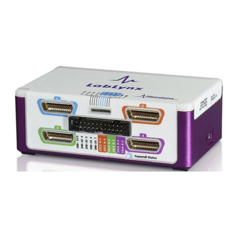
Neuralynx LabLynx User manual

LabLynx User’s Manual Revision 1.0 2019-01-15
Page 2of 30
Table of Contents
1Document Overview................................................................................................... 5
2LabLynx Overview..................................................................................................... 5
2.1 LabLynx Components.......................................................................................... 6
2.1.1 LabLynx Base............................................................................................... 6
2.1.2 Battery Charger Cable................................................................................... 6
2.1.3 Wireless access point kit............................................................................... 6
2.1.4 16 or 32 channel MUX Headstage................................................................ 6
2.2 Electrostatic Sensitive Equipment........................................................................ 7
2.3 Recommended Additional Products..................................................................... 7
2.3.1 Neuralynx Digital Multiplexing (MUX) Headstages ................................... 7
2.3.2 Signal Mouse ................................................................................................ 7
2.3.3 Minirator Kit................................................................................................. 7
2.3.4 HS-36-MUX Impedance Plug....................................................................... 8
2.3.5 2Pin to BNC Cable........................................................................................ 8
2.3.6 Neuralynx Halo Microdrives ........................................................................ 8
3Quick Start .................................................................................................................. 9
3.1 Connecting a LabLynx to a PC............................................................................ 9
3.2 Set Ethernet port IP address............................................................................... 10
3.2.1 Clear LabLynx for firewall......................................................................... 10
3.2.2 Configure Cheetah for specific LabLynx setup.......................................... 10
3.3 Software quick start............................................................................................ 12
3.3.1 Start Cheetah and turn on LabLynx............................................................ 12
3.3.2 Connect LabLynx to test setup ................................................................... 12
Drive Signal into LabLynx ....................................................................................... 13
4Hardware Overview.................................................................................................. 17
4.1 Enclosure overview............................................................................................ 17
4.1.1 UDB-25 input connector............................................................................. 18
4.1.2 10 Pin connector ......................................................................................... 21
4.1.3 24 Pin connector ......................................................................................... 21
4.1.4 Transmit Status Indicator............................................................................ 22
4.1.5 ON/Off Push button.................................................................................... 22
4.1.6 Manufacturing Access Panel....................................................................... 22
4.1.7 Battery Charger........................................................................................... 22
4.1.8 Battery Charge indicator............................................................................. 22
4.1.9 Back Panel Mounting locations.................................................................. 23
4.2 LabLynx Amplifier and A/D Converter............................................................. 23
4.3 LabLynx Communication .................................................................................. 23
4.4 Optimizing data stream and masking CSC ........................................................ 24
4.4.1 Channel masking overview......................................................................... 24
4.4.2 Channel mapping overview ........................................................................ 24
5Optimizing Wifi channel........................................................................................... 25
1Software Overview ................................................................................................... 26
2Configuring TTL inputs............................................................................................ 26
LabLynx Commands......................................................................................................... 27
2.1 WHSSetDigitalIOPortDirection......................................................................... 27

LabLynx User’s Manual Revision 1.0 2019-01-15
Page 3of 30
2.2 WHSSetDigitalIOBit.......................................................................................... 28
2.3 WHSSetDigitalIOPortValue .............................................................................. 28
2.4 WHSSetTransmittedChannels............................................................................ 29
Neuralynx Contact ........................................................................................................ 30

LabLynx User’s Manual Revision 1.0 2019-01-15
Page 4of 30
List of Figures and Tables
Figure 2.1 LabLynx Base.................................................................................................... 6
Figure 2.2 Picture of Mini-USB adapter............................................................................. 6
Figure 2.3 Ruckus Router................................................................................................... 6
Figure 2.4 16 and 32 channel MUX Headstage.................................................................. 6
Figure 2.5 HS-64-MUX...................................................................................................... 7
Figure 2.6 HS-64-MUX Signal Mouse............................................................................... 7
Figure 2.7 Minirator Kit...................................................................................................... 7
Figure 2.8 HS-36-MUX Impedance Plug........................................................................... 8
Figure 2.9 2Pin to BNC Cable............................................................................................ 8
Figure 2.10 Halo-5 Microdrive........................................................................................... 8
Figure 3.1 Connecting Wireless Access point to PC with POE Injector............................ 9
Figure 3.2 Setting static IP................................................................................................ 10
Figure 3.3 Setting Hardware Sub-System......................................................................... 11
Figure 3.4 Setting Channel configuration......................................................................... 11
Figure 3.5 Bank 1, 2, 3 and 4 Switches Up. Reference Switch Down. ............................ 13
Figure 3.6 Bank 2, 3 and 4 Switches Up. Bank 1 and Reference Switches Down........... 13
Figure 3.7 Bank 3 and 4 Switches Up. Bank 1, 2 and Reference Switches Down........... 14
Figure 3.8 Bank 4 Switches Up. Bank 1, 2, 3 and Reference Switches Down................. 15
Figure 3.9 All Switches Down (1000µV Input Range).................................................... 15
Figure 3.10 All Switches Down (25µV Input Range)...................................................... 16
Figure 3.11 All Switches Up (25µV Input Range)........................................................... 16
Figure 4.1 Front Panel, Top Lid, and On/off isometric view ........................................... 17
Figure 4.2 Bottom, Battery Charger, and Back Panel isometric view.............................. 17
Figure 4.3 Connector 1 Pin out......................................................................................... 18
Figure 4.4 Connector 2 Pin out......................................................................................... 19
Figure 4.5 Connector 3 Pin out......................................................................................... 19
Figure 4.6Connector 4 Pin out.......................................................................................... 20
Figure 4.7 10 Pin connector Pin out.................................................................................. 21
Figure 4.8 24 pin connector pin out.................................................................................. 21

LabLynx User’s Manual Revision 1.0 2019-01-15
Page 5of 30
1Document Overview
This document describes the specifications and features of the LabLynx. It also explains
how to set up, test, and use your LabLynx. There is a glossary at the end of the document.
2LabLynx Overview
The LabLynx is a portable battery powered digital Acquisition system. It is capable of
recording from up to 256 individual electrodes through the use of Neuralynx Digital
Multiplexing Headstages, MUX. The physiological signals are digitized at the Neuralynx
MUX Headstage and transmitted wirelessly from the LabLynx via 5G WiFi to a wireless
access point connected to a PC running Cheetah software.
Features:
16-256 Channels
Up to eight GPIO for TTL inputs
8.5 hour wireless run-time
7 hour Charge time
Record from up to four different digital Headstages
16 Bit Resolution
±5mV Input Range
>80dB Common Mode Rejection Ratio (CMRR) at 60Hz
<2.5µVRMS Noise (0.1Hz to 8kHz)
Compatible with Neuralynx FLEDs
Compatible with Neuralynx EIBs
Compatible with Neuralynx MUX Headstages
30KHz Sampling Rate

LabLynx User’s Manual Revision 1.0 2019-01-15
Page 6of 30
2.1 LabLynx Components
2.1.1 LabLynx Base
four udb25 connectors for connection to
digital Headstage
FLED driver input
Eight GPIO inputs
On/off push button
Mini USB charging input
Four 4-40 mounting holes
Figure 2.1 LabLynx Base
2.1.2 Battery Charger Cable
A grounded Mini-USB to barrel connector cable
adapter necessary to charge the batteries of the
LabLynx while device is in use.
5 V Power Supply
Power Cable associated with country of origin.
Figure 2.2 Picture of
Mini-USB adapter
2.1.3 Wireless access point kit
48 V power supply
Ruckus Router
POE Injector
Standard Ethernet cables
Figure 2.3 Ruckus Router
2.1.4 16 or 32 channel MUX Headstage
Users choice of one comes standard
with system
Figure 2.4 16 and 32 channel MUX
Headstage

LabLynx User’s Manual Revision 1.0 2019-01-15
Page 7of 30
2.2 Electrostatic Sensitive Equipment
All Neuralynx Equipment is Electrostatic Sensitive and should be handled with
appropriate measures. Always wear a static strap and use all appropriate ESD
measures when handling any electronics. Please contact Neuralynx for detailed
information if you have questions.
2.3 Recommended Additional Products
Neuralynx provides additional products to support the assembly and use of the
LabLynx, and to enhance multichannel electrophysiological research.
2.3.1 Neuralynx Digital Multiplexing (MUX) Headstages
Digitize Neural signals on the headstage
Reduce tether wire count, weight, size and cost
30KHz sampling rate / 16 bit resolution
Note: image is just one of many different MUX
headstages
Figure 2.5 HS-64-MUX
2.3.2 Signal Mouse
Simulates a live subject by sending a 1000:1 reduced
signal to all input channels of a Headstage for testing
purposes.
Note: image is just one of several different Signal
Mice
Figure 2.6 HS-64-
MUX Signal Mouse
2.3.3 Minirator Kit
A convenient, battery powered, handheld signal
generator that outputs Sine/Ramp/Noise waves to
simulate spikes
Figure 2.7 Minirator
Kit

LabLynx User’s Manual Revision 1.0 2019-01-15
Page 8of 30
2.3.4 HS-36-MUX Impedance Plug
Provides different resistance values in banks of 8 for
multiple testing applications on 32/64 channel
multiplexing (MUX) headstages
Figure 2.8 HS-36-
MUX Impedance
Plug
2.3.5 2Pin to BNC Cable
Provides a signal and ground BNC connection for
signals from 2 pins of male IDC-Panel-mount
Ribbon-cable style connector
Figure 2.9 2Pin to
BNC Cable
2.3.6 Neuralynx Halo Microdrives
Light weight, easy to construct, and cost effective
microdrives for tetrode freely moving animal
research.
Figure 2.10 Halo-5
Microdrive

LabLynx User’s Manual Revision 1.0 2019-01-15
Page 9of 30
3Quick Start
The LabLynx can be configured to work directly with a PC running cheetah. If the
LabLynx is sold with a PC as a system it will come pre-configured. A standard
LabLynx license for Cheetah is Non-transferrable meaning that Cheetah will only
operate with a LabLynx. If a standard Neuralynx cheetah license is already owned
the LabLynx will seamlessly interface with the cheetah computer.
The LabLynx is configured to work with up to 256 channels out of the box. Actual
channels a user may use is defined by the Cheetah license. To map and mask unused
channels view section 4.4.
3.1.1 Connecting a LabLynx to a PC
To connect a LabLynx directly to a PC first check to ensure the PC meets
the minimum system requirements. These are outlined on the Neuralynx
website in the support section. Next, follow the diagram below to ensure
you connect the necessary hardware, and then follow the steps identified
to ensure the LabLynx Connects to the PC through the wireless access
point. It is recommended that the Ruckus Router wireless access point be
mounted on the ceiling for best performance.
Figure 3.1 Connecting Wireless Access point to PC with POE Injector
Step
Function
1
Connect the 48V Power Supply to a standard wall outlet.
2
Connect the standard Ethernet Cable to the Ethernet port of the PC
3
Connect the 48 V Power Supply to the POE Injector
4
Connect the standard Ethernet Cable to POE Injector
5
Connect the POE Ethernet Cable to the output side of the POE Injector
6
Connect the POE Ethernet Cable to the Ethernet port on the Ruckus Router

LabLynx User’s Manual Revision 1.0 2019-01-15
Page 10 of 30
labeled POE
3.2 Set Ethernet port IP address
To enable the means of communication between the LabLynx and the acquisition
PC a static IP address for the wireless access point must be set. To set the static IP
address follow control panel directory > network and sharing center > change
adapter settings (located on column on left of window) > local area connection
(right click properties) > Internet Protocol Version 4 (TCP/IPv4) > set up IP
address as below image
Figure 3.2 Setting static IP
Next jumbo packets will need to be enabled. From the same properties window >
configure > advanced > scroll to jumbo packets set value to 9014 Bytes.
3.2.1 Clear LabLynx for firewall
If a PC is using a firewall it may get in the way of the LabLynx connecting
to the Ruckus Router. Check to see if there is a firewall in place and if
there is a firewall, disable it from blocking the port connecting the
LabLynx.
3.2.2 Configure Cheetah for specific LabLynx setup
Open Cheetah and select the appropriate configuration for your setup. To
find configuration files follow directory
C:\Users\Public\Documents\Cheetah\Configuration. Open the Cheetah.cfg
using notepad and check that the Acquisition system setup has
LabLynx.cfg unchecked.

LabLynx User’s Manual Revision 1.0 2019-01-15
Page 11 of 30
Figure 3.3 Setting Hardware Sub-System
Also match the channel configuration to your specification setup. In the
example below the system is setup for 32csc files.
Figure 3.4 Setting Channel configuration

LabLynx User’s Manual Revision 1.0 2019-01-15
Page 12 of 30
3.3 Software quick start
This will guide you through starting Cheetah Software, starting a configured
LabLynx, and testing the system using a minirator HS-32-MUX and a signal mouse.
3.3.1 Start Cheetah and turn on LabLynx
After the Cheetah Configuration files have been updated to the desired
configuration, open Cheetah using the saved configurations. While
Cheetah is booting start the LabLynx using the push button on the side.
Once the LabLynx is started, a blue light will display on the Transmit
Status LED indicator, this means the LabLynx is pairing. After the
LabLynx has booted and gets connected to Cheetah the indicator light
turns green and the LabLynx is ready to transmit data. To view further
indicator light specifications view section 4.1.4.
Notes:
There is a 60 second window for the LabLynx to pair with Cheetah during the
boot process.
The LabLynx looks for the Connected Digital Multiplexing Headstage connected
at boot up. Therefore there is no hot swapping of Headstages while the LabLynx
is operating.
Every time the LabLynx is restarted the Cheetah software must be restarted as
well.
3.3.2 Connect LabLynx to test setup
number
Function
1
Set the Minirator, or other signal source, to output a 1VPP Sine Wave at 100 Hz.
The Signal Mouse will reduce this signal to roughly to 1mVPP.
2
Connect the Minirator, or other signal source, to the Signal Mouse using a BNC
Cable.
3
Connect HS-64-Mux to the two Omnetics connectors located on the HS-64-mux
Signal Mouse
4
Turn the Bank 1, 2, 3, and 4 switches on the Signal Mouse to the Signal Position
(Up). Turn the Reference switch on the Signal Mouse to the Ground Position
(Down).
5
Connect the uDB25 connector from the HS-64-mux into connector 1 of the
LabLynx.

LabLynx User’s Manual Revision 1.0 2019-01-15
Page 13 of 30
Drive Signal into LabLynx
In Cheetah, select the ACQ Button to Start Acquisition. Set the Input Range for all 64
CSCs to 1000µV. Each should show a roughly 1mVPP version of the Minirator output.
Figure 3.5 Bank 1, 2, 3 and 4 Switches Up. Reference Switch Down.
Switch the Bank 1 Switch to the Ground Position (Down). CSCs 1-8 and 33-40 should
now be flat-lined while CSCs 9-32 and 41-64 should still show a roughly 1mVPP version
of the Minirator output. Refer to the figure below.
Figure 3.6 Bank 2, 3 and 4 Switches Up. Bank 1 and Reference Switches Down.

LabLynx User’s Manual Revision 1.0 2019-01-15
Page 14 of 30
Switch the Bank 2 Switch to the Ground Position (Down). CSCs 1-16 and 33-48 should
now be flat-lined while CSCs 17-32 and 49-64 should still show a roughly 1mVPP version
of the Minirator output.
Figure 3.7 Bank 3 and 4 Switches Up. Bank 1, 2 and Reference Switches Down.

LabLynx User’s Manual Revision 1.0 2019-01-15
Page 15 of 30
Switch the Bank 3 Switch to the Ground Position (Down). CSCs 1-24 and 33-56 should
now be flat-lined while CSCs 25-32 and 57-64 should still show a roughly 1mVPP version
of the Minirator output.
Figure 3.8 Bank 4 Switches Up. Bank 1, 2, 3 and Reference Switches Down.
Switch the Bank 4 Switch to the Ground Position (Down). CSCs 1-64 should now be flat-
lined.
Figure 3.9 All Switches Down (1000µV Input Range)

LabLynx User’s Manual Revision 1.0 2019-01-15
Page 16 of 30
Set the Input Range for all 64 CSCs to 25µV. CSCs 1-64 now show the baseline noise.
Each should be less than 25µVpp and be void of any repetitive signals.
Figure 3.10 All Switches Down (25µV Input Range)
Switch all the Switches to the Signal Position (Up). Each should be less than 25µVpp and
be void of any repetitive signals.
Figure 3.11 All Switches Up (25µV Input Range)

LabLynx User’s Manual Revision 1.0 2019-01-15
Page 17 of 30
4Hardware Overview
A detailed overview of all user interfaces as well as their functions.
4.1 Enclosure overview
Figure 4.1 uDB-25 Connector, 10 Pin Connector, 24 Pin Connector, Transmit Status
Indicator, Battery Charger / Battery Charge Indicator Locations
Figure 4.2 Bottom, Battery Charger, and Back Panel isometric view

LabLynx User’s Manual Revision 1.0 2019-01-15
Page 18 of 30
4.1.1 UDB-25 input connector
The UDB-25 connector is the standard Neuralynx connector used to
connect to MUX Headstages. The LabLynx enables up to four different
uDB25 connections or four different mux Headstage. Each uDB25
connector has two Stim pairs which can be used to either drive a stimulus
current or a FLED as well as the digital lines used to communicate with
the digital Headstage. UDB-25 connector 1 stimulus lines are routed to the
10 connector so that it can be driven with the Modular FLED driver. Stim
channels on connectors 2, 3, and 4 are routed to the 24 pin connector.
Routing of channels is easy to follow with color coding on the label as
well as pins labeled. A C2S2 stands for Connector 2 Stim channel 2. Pin
outs for each of the four connectors are labeled below.
Figure 4.3 Connector 1 Pin out

LabLynx User’s Manual Revision 1.0 2019-01-15
Page 19 of 30
Figure 4.4 Connector 2 Pin out
Figure 4.5 Connector 3 Pin out

LabLynx User’s Manual Revision 1.0 2019-01-15
Page 20 of 30
Figure 4.6Connector 4 Pin out
Other manuals for LabLynx
1
Table of contents
Other Neuralynx Data Logger manuals

