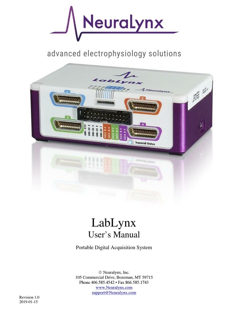
Neuralynx LabLynx User manual

LabLynx User Manual Revision 1.1 2/18/2021 2
Table of Contents
Document Overview................................................................................................... 5
LabLynx Overview..................................................................................................... 5
LabLynx Components and Accessories...................................................................... 6
LabLynx Base ...................................................................................................... 6
Battery Charger.................................................................................................... 6
Wireless Access Point.......................................................................................... 6
16 or 32 channel Mux Headstage......................................................................... 7
Recommended Additional Products..................................................................... 7
Digital Multiplexing (mux) Headstages........................................................ 7
Signal Mouse ................................................................................................ 7
Minirator....................................................................................................... 8
HS-36-mux Impedance Plug......................................................................... 8
2-Pin to BNC Cable...................................................................................... 8
Neuralynx Halo Microdrives ........................................................................ 8
Setup ........................................................................................................................... 9
Electrostatic Sensitive Equipment........................................................................ 9
Hardware Setup.................................................................................................. 10
Set Computer IP Address................................................................................... 11
Enable Jumbo Packets........................................................................................ 13
Using Cheetah with LabLynx ............................................................................ 14
Start Cheetah and Turn LabLynx On.......................................................... 16
Connect LabLynx to Test Setup ................................................................. 16
Test the LabLynx with a Test Input Signal................................................. 17
Troubleshooting.......................................................................................... 20
Channel Mapping and Channel Masking........................................................... 21
Channel Mapping........................................................................................ 21
Channel Masking........................................................................................ 21
Hardware Overview.................................................................................................. 22
Enclosure............................................................................................................ 22
uDB-25 Connector...................................................................................... 23
10-pin Connector ........................................................................................ 25
24-pin Connector ........................................................................................ 25
Status LED.................................................................................................. 26
On/Off Push Button .................................................................................... 27
Manufacturing Access Panel....................................................................... 27
Battery Charger........................................................................................... 27
Battery Charge Indicator............................................................................. 27
Back Panel Mounting Locations................................................................. 27
Amplifier and Analog to Digital Converter ....................................................... 28
Wireless Communication................................................................................... 29
Wireless Access Point Setup....................................................................... 29
Selecting a Good Wi-Fi Channel................................................................ 30
Configuring TTLs..................................................................................................... 32
LabLynx Commands................................................................................................. 32

LabLynx User Manual Revision 1.1 2/18/2021 3
SetDigitalIOPortDirection.................................................................................. 33
Example .cfg File Text................................................................................ 33
SetDigitalIOBit................................................................................................... 34
Example .cfg File Text................................................................................ 34
GetDigitalIOPortValue....................................................................................... 35
Example .cfg File Text................................................................................ 35
SetDigitalIOPortValue....................................................................................... 35
Example .cfg File Text................................................................................ 35
GetTransmittedChannels.................................................................................... 35
Example .cfg File Text................................................................................ 35
SetTransmittedChannels..................................................................................... 36
Example .cfg File Text................................................................................ 38
Neuralynx Contact .................................................................................................... 38

LabLynx User Manual Revision 1.1 2/18/2021 4
List of Figures and Tables
Figure 3-1 LabLynx Base ................................................................................................... 6
Figure 3-2 Mini-USB Charger............................................................................................ 6
Figure 3-3 Wireless Access Point....................................................................................... 6
Figure 3-4 16 and 32 channel Mux Headstages.................................................................. 7
Figure 3-5 HS-64-mux........................................................................................................ 7
Figure 3-6 HS-64-mux Signal Mouse................................................................................. 7
Figure 3-7 Minirator ........................................................................................................... 8
Figure 3-8 HS-36-mux Impedance Plug............................................................................. 8
Figure 3-9 2-Pin to BNC Cable .......................................................................................... 8
Figure 3-10 Halo-5 Microdrive........................................................................................... 8
Figure 4-1 Steps to Connect Access Point to PC.............................................................. 10
Figure 4-2 Network Interface Properties .......................................................................... 11
Figure 4-3 Computer IP Address Settings........................................................................ 12
Figure 4-4 Uncomment LabLynx.cfg ............................................................................... 14
Figure 4-5 Setting Channel Configuration........................................................................ 15
Figure 4-6 Bank 1, 2, 3 and 4 Switches Up. Reference Switch Down............................. 17
Figure 4-7 Bank 2, 3 and 4 Switches Up. Bank 1 and Reference Switches Down........... 17
Figure 4-8 Bank 3 and 4 Switches Up. Bank 1, 2 and Reference Switches Down........... 18
Figure 4-9 Bank 4 Switches Up. Bank 1, 2, 3 and Reference Switches Down ................ 18
Figure 4-10 All Switches Down (1000 µV Input Range)................................................. 19
Figure 4-11 All Switches Down (25 µV Input Range)..................................................... 19
Figure 4-12 All Switches Up (25 µV Input Range).......................................................... 20
Figure 5-1 Enclosure Front View ..................................................................................... 22
Figure 5-2 Enclosure Flipped View.................................................................................. 22
Figure 5-3 Connector 1 Pinout.......................................................................................... 23
Figure 5-4 Connector 2 Pinout.......................................................................................... 23
Figure 5-5 Connector 3 Pinout.......................................................................................... 24
Figure 5-6 Connector 4 Pinout.......................................................................................... 24
Figure 5-7 10-pin Connector Pinout................................................................................. 25
Figure 5-8 24-pin Connector Pinout................................................................................. 25
Figure 5-9 5 LabLynx Set to Channel 106........................................................................ 30
Figure 5-10 Login Page using Microsoft Edge................................................................. 31
Figure 5-11 Changing WiFi Channel................................................................................ 31

LabLynx User Manual Revision 1.1 2/18/2021 5
Document Overview
This document describes the specifications and features of the LabLynx. It also explains
how to set up, test, and use your LabLynx.
LabLynx Overview
The LabLynx is a portable, battery powered digital acquisition system. It is capable of
recording from up to 256 individual electrodes using Neuralynx digital multiplexing
(mux) headstages. The physiological signals are digitized at the Neuralynx mux
headstage and transmitted wirelessly from the LabLynx. Wireless communication uses
5 GHz WiFi (802.11 ac).
Features:
•Wirelessly transmit up to 256 channels
•Record up to 256 channels to microSD card
•Record from up to four different digital (mux) headstages
•8.5 hour wireless run-time
•7 hour charge time
•Time synchronization with Cheetah to within ±5 ms
•30 KHz Sampling Rate
•16-bit Resolution
•±5 mV Input Range
•>80 dB Common Mode Rejection Ratio (CMRR) at 60 Hz
•<2.5 µVRMS Noise (0.1 Hz to 8 kHz)
•Up to eight TTL-compatible digital IO
•Compatible with Neuralynx FLEDs
•Compatible with Neuralynx EIBs
•Compatible with Neuralynx mux headstages

LabLynx User Manual Revision 1.1 2/18/2021 6
LabLynx Components and Accessories
LabLynx Base
•Four uDB-25 connectors
for digital headstages
•FLED driver input
•Eight GPIO inputs
•On/off push button
•Mini-USB charging input
•Four 4-40 mounting holes
Figure 3-1 LabLynx Base
Battery Charger
•A grounded mini-USB to barrel
connector cable adapter necessary to
charge the batteries of the LabLynx
while device is in use.
•5 V power supply
•Power cable associated with country
of origin.
Figure 3-2 Mini-USB Charger
Wireless Access Point
•Wireless access point
•POE Injector
•Power supply
•Standard Ethernet cables
Figure 3-3 Wireless Access Point

LabLynx User Manual Revision 1.1 2/18/2021 7
16 or 32 channel Mux Headstage
•One headstage comes standard with the LabLynx
system
Figure 3-4 16 and 32
channel Mux
Headstages
Recommended Additional Products
Neuralynx provides additional products to support the assembly and use of the LabLynx.
Digital Multiplexing (mux) Headstages
•Digitize neural signals at the headstage
•Reduce the wire count, weight, size and
cost of the tether
•30 kHz sampling rate, 16-bit resolution
•A wide variety of mux headstages are
available
Figure 3-5 HS-64-mux
Signal Mouse
•Verify your recording setup by inputting a
test signal into all headstage channels
Figure 3-6 HS-64-mux Signal
Mouse

LabLynx User Manual Revision 1.1 2/18/2021 8
Minirator
•A convenient, battery powered, handheld signal
generator that outputs Sine/Ramp/Noise waves to
simulate spikes
•This device can be used to supply test signal into a
Signal Mouse
Figure 3-7 Minirator
HS-36-mux Impedance Plug
•Provides different resistance values in banks of 8 for
multiple testing applications on 32/64 channel
multiplexing (mux) headstages
Figure 3-8 HS-36-mux
Impedance Plug
2-Pin to BNC Cable
•Connect signal and ground between a BNC
and a standard, male 0.10” pitch connector
Figure 3-9 2-Pin to BNC
Cable
Neuralynx Halo Microdrives
•Light weight, easy to construct, and cost effective
microdrives for tetrode freely moving animal
research.
Figure 3-10 Halo-5
Microdrive

LabLynx User Manual Revision 1.1 2/18/2021 9
Setup
The LabLynx communicates wirelessly with a PC running Cheetah. A standard LabLynx
license for Cheetah is non-transferrable. Your LabLynx license only allows use of
Cheetah with a LabLynx. If you purchased your LabLynx with a PC, your system would
be pre-configured. If you already own a standard Neuralynx Cheetah license, the
LabLynx can be used with Cheetah. The LabLynx requires Cheetah 6.4 or later.
LabLynx supports up to 256 channels. The number of channels that can be viewed and
recorded in Cheetah depends on the Cheetah license.
If you need to change the order of acquisition channels or reduce the number of channels
recorded, see section 4.6 Channel Mapping and Channel Masking.
Electrostatic Sensitive Equipment
All Neuralynx equipment is sensitive to electrostatic discharge (ESD) and should be
handled appropriately. Always wear a static wrist strap and use appropriate ESD
measures when handling any electronics. If you have questions, please contact Neuralynx
for more information.

LabLynx User Manual Revision 1.1 2/18/2021 10
Hardware Setup
To connect a LabLynx directly to a PC first check to ensure the PC meets the minimum
system requirements. These are outlined on the Neuralynx website in the support section.
Next, follow the diagram below to ensure you connect the necessary hardware, and then
follow the steps identified to ensure the LabLynx Connects to the PC through the wireless
access point. It is recommended that the Ruckus Router wireless access point be mounted
on the ceiling for best performance.
Figure 4-1 Steps to Connect Access Point to PC
Step
Function
1
Connect the 48 V power supply to a standard wall outlet.
2
Connect Ethernet cable A to the Ethernet port on the PC
3
Connect the 48 V power supply to the PoE Injector
4
Connect Ethernet cable A to the LAN IN port of the PoE Injector
5
Connect Ethernet cable B to the POWER+DATA OUT port of the PoE Injector
6
Connect Ethernet cable B to the PoE port on the access point

LabLynx User Manual Revision 1.1 2/18/2021 11
Set Computer IP Address
To enable communication between the LabLynx and the acquisition PC, a static IP
address must be set for the network interface that is used to connect to the wireless access
point. To set the static IP address, go to:
Control Panel > Network and Internet > Network and Sharing Center > Change Adapter Settings
Determine the appropriate network connection and open its properties.
Figure 4-2 Network Interface Properties

LabLynx User Manual Revision 1.1 2/18/2021 12
Set the IP information as shown below.
Figure 4-3 Computer IP Address Settings

LabLynx User Manual Revision 1.1 2/18/2021 14
Using Cheetah with LabLynx
Open Cheetah and select the appropriate configuration file for your setup. Open
Cheetah.cfg using a text editor like Notepad or Notepad++ and check that the Acquisition
System Setup has LabLynx.cfg uncommented as seen below. A line in a .cfg file is
uncommented by deleting the # at the start of the line.
Figure 4-4 Uncomment LabLynx.cfg
Select a channel configuration compatible with your setup by uncommenting the
appropriate line. In the example below, the system is setup for 32 channels. A CSC
(Continuously Sampled Channel) setup will plot 32 channels on the display.

LabLynx User Manual Revision 1.1 2/18/2021 15
Figure 4-5 Setting Channel Configuration

LabLynx User Manual Revision 1.1 2/18/2021 16
Start Cheetah and Turn LabLynx On
Open Cheetah using the configuration file you edited above, Cheetah.cfg. While Cheetah
is loading, turn on the LabLynx using the push button on the side. When the LabLynx is
turned on, the status LED will turn blue. After the LabLynx has booted and connected to
Cheetah, the status LED turns green. LED codes are described in 5.1.4 Status LED.
•Cheetah will attempt to connect with the LabLynx for 60 seconds before it times
out.
•The LabLynx detects connected headstages during bootup. Therefore, headstages
must be connected to the LabLynx before turning the LabLynx on. Headstages
connected after bootup will not function.
Connect LabLynx to Test Setup
Step
Description
1
Set the Minirator, or other signal source, to output a 1 VPP sine wave at 100 Hz.
The Signal Mouse will reduce this signal to approximately to 1 mVPP.
2
Connect the Minirator, or other signal source, to the Signal Mouse using a BNC
cable.
3
Connect HS-64-mux to the two Omnetics connectors located on the HS-64-mux
Signal Mouse
4
Turn the Bank 1, 2, 3, and 4 switches on the Signal Mouse to the Signal position
(Up). Turn the Reference switch on the Signal Mouse to the Ground position
(Down).
5
Connect the uDB-25 connector from the HS-64-mux into connector 1 of the
LabLynx.

LabLynx User Manual Revision 1.1 2/18/2021 17
Test the LabLynx with a Test Input Signal
In Cheetah, select the ACQ button to start acquisition. Set the Input Range for all 64
CSCs to 1000 µV. Each should show approximately 1 mVPP sine waves.
Figure 4-6 Bank 1, 2, 3 and 4 Switches Up. Reference Switch Down
Switch the Bank 1 switch to the Ground position (down). CSCs 1-8 and 33-40 should
now be flat-lined while CSCs 9-32 and 41-64 should still show 1 mVPP sine waves.
Figure 4-7 Bank 2, 3 and 4 Switches Up. Bank 1 and Reference Switches Down

LabLynx User Manual Revision 1.1 2/18/2021 18
Switch the Bank 2 switch to the Ground position (down). CSCs 1-16 and 33-48 should
now be flat-lined while CSCs 17-32 and 49-64 should still show 1 mVPP sine waves.
Figure 4-8 Bank 3 and 4 Switches Up. Bank 1, 2 and Reference Switches Down
Switch the Bank 3 switch to the Ground position (down). CSCs 1-24 and 33-56 should
now be flat-lined while CSCs 25-32 and 57-64 should still show 1 mVPP sine waves.
Figure 4-9 Bank 4 Switches Up. Bank 1, 2, 3 and Reference Switches Down

LabLynx User Manual Revision 1.1 2/18/2021 19
Switch the Bank 4 switch to the Ground position (down). CSCs 1-64 should now be flat-
lined.
Figure 4-10 All Switches Down (1000 µV Input Range)
Set the Input Range for all 64 CSCs to 25 µV. CSCs 1-64 now show the baseline noise.
Each should be less than 25 µVpp and without repetitive signals such as 60 Hz noise.
Figure 4-11 All Switches Down (25 µV Input Range)

LabLynx User Manual Revision 1.1 2/18/2021 20
Switch all the switches to the Signal position (up). Each should be less than 25 µVpp and
without repetitive signals such as 60 Hz noise.
Figure 4-12 All Switches Up (25 µV Input Range)
Troubleshooting
If Cheetah does not receive data after starting acquisition, your firewall might be
preventing Cheetah from receiving LabLynx data.
Other manuals for LabLynx
1
Table of contents
Other Neuralynx Data Logger manuals
Popular Data Logger manuals by other brands

Crane Electronics
Crane Electronics TorqueStar Plus Operator's manual

Shenzhen MobileX Technology
Shenzhen MobileX Technology MX8880 quick start guide

Racelogic
Racelogic Performance Box Touch V2 manual
Capetti Elettronica
Capetti Elettronica WineCap WSD12-2DI user manual
NexSens
NexSens 3100-iSIC manual
Transcat
Transcat Dickson FH320 user manual


