Neurio W1 User manual
Check the Panel
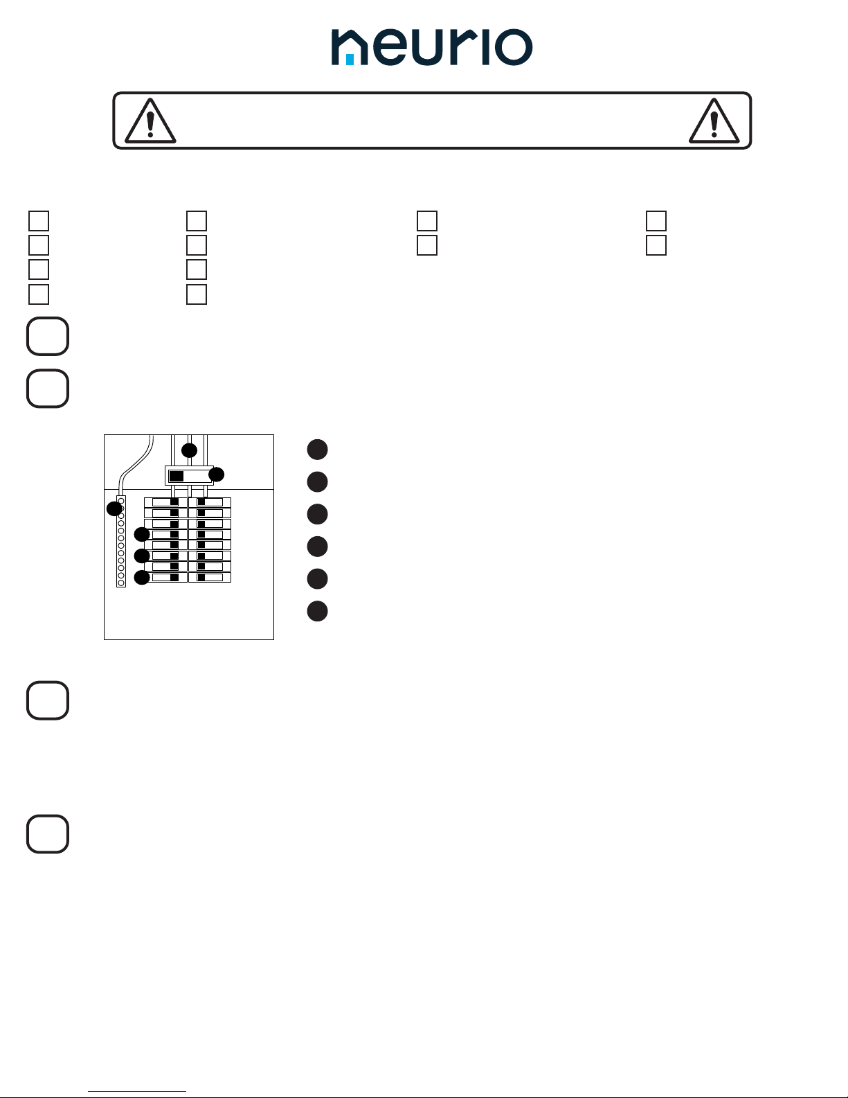
Take the cover o the panel. It should look something like this:
1Mains Service Wires
2Main Breaker
415A or 20A Single-pole Breaker on Phase A
Mount Neurio
The leads on the CTs are 4ft long, and the voltage cables are 2ft long. Try to nd a location that’s within 4ft of
the mains service wires and 2ft of the breakers and the neutral bus bar. Make sure there’s enough room on
either side of Neurio to connect the CTs, voltage cable, and antenna cable.
Once you’ve found your location, drill the two self-drilling mounting screws into the panel to mount Neurio.
Connect the Voltage Cable
Plug the voltage cable to the matching connector port on Neurio.
100.00029A.A
515A or 20A Single-pole Breaker on Phase B
615A or 20A Single-pole Breaker on Phase C
You might also have to remove a service entrance cover on the high side of the main breaker to access the
mains wires. Remember that there may be voltage on the high side of the main breaker.
Got Everything?
3Neutral Bus Bar
1
Neurio Sensor W1
Voltage Cable
Antenna Cable
Antenna
Neurio Sensor Box Tools3-Phase Kit
2 Current Transformers (CTs)
2 Self-Drilling Screws
2 Antenna Mounts
2 Wire Taps Phillips #2 Bit and
Cordless Drill
Multimeter (Optional)
1 Current Transformer (CT)
1 Wire Tap
Turn Off the Main Breaker
2
Neurio should only be installed when the main breaker in the panel is turned o.
3
4
This product must be installed by an electrician or other qualified professional.
Before following this guide, please read and review the safety warnings provided
at the end of this guide.
Repeat for the red and blue wires, being sure to use breakers on dierent phases. We’ll call the phase that
the red wire connects to Phase B, and the phase that the blue wire connects to Phase C. Alternatively, you
can connect the black, red, and blue wires to an empty 3-phase breaker if one is available. For tips on nding
breakers on dierent phases, see Step 4 of the 2-Phase Installation Guide.
If an empty breaker is available, connect Neurio’s black wire to it. If no breakers are available, disconnect the
wire from an occupied 15A or 20A breaker, and replace it with a jumper wire of equivalent or lower gauge.
Use the included wire tap to connect the jumper wire, Neurio’s black wire, and the original wire back to this
breaker. Let’s call this phase Phase A.
Take the white wire and connect it to the neutral bus bar.
3-Phase Installation Guide
Connect the Current Transformers
Determine which mains wire feeds the breaker that you connected Neurio’s black wire to (Phase A). Trace
the line visually or use your multimeter to nd the wire. Remember that there may be voltage on the high
side of the main breaker.
Connect the Antenna
Connect the antenna cable to the antenna connector on your Neurio. Feed the other end of the antenna
cable through either the 0.5”or 0.75“ antenna mount. Use whichever size matches the knockouts in your
panel. Fasten the antenna cable onto the mount using the nut that is supplied on the cable. Then connect
your antenna to the antenna cable.
Check Your Work
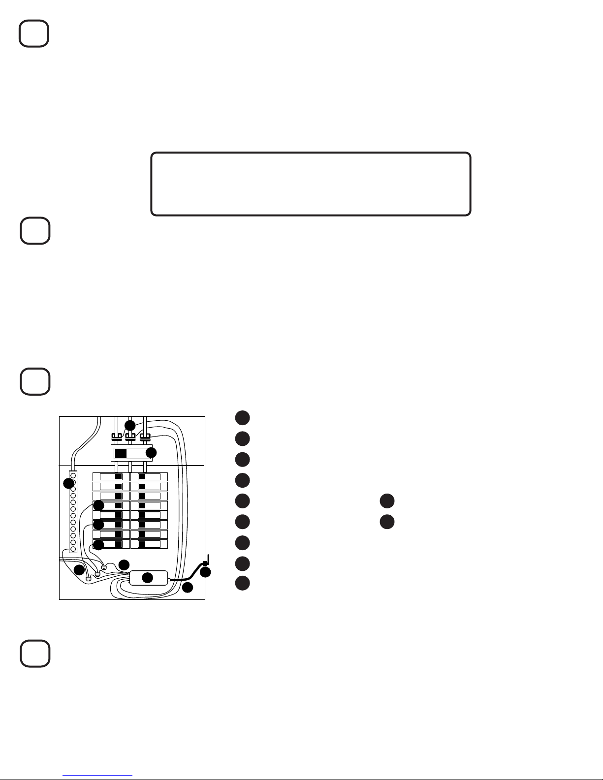
Now the panel should look something like this:
1Mains Service Wires and 3 CTs, Connected to Ports #1, 2, and 3
5Main Breaker
6Neutral Bus Bar
7Neurio
8Voltage Cable
215A or 20A Single-pole Breaker on Phase A
315A or 20A Single-pole Breaker on Phase B
You should have three CTs on the mains, each with their labels facing away from the main breaker. The
voltage cable should be connected to 3 breakers on dierent phases and the neutral bus bar.
415A or 20A Single-pole Breaker on Phase C
11 Antenna and antenna mount
10 Antenna cable
5
6
7
Clip a CT around the mains wire you found. It should have its white labels facing away from the main
breaker. Plug this CT into port #1 on Neurio. Repeat this process for the red and blue wires. The CT on the
same phase as the red wire (Phase B) should connect to port #2, and the CT on the blue wire’s phase
(Phase C) should connect to port #3.
Find a 0.5” or 0.75” knockout that is within reach of your Neurio using the included antenna cable. Most
of the 0.5“ and 0.75” knockouts will have an inner knockout and an outer ring. For either size, you only
need to remove the inner knockout and should leave the outer ring in place. Use a screwdriver to remove
the inner knockout. Feed the antenna mount through the knockout until it clips into position. For more
detailed instructions and pictures, refer to Step 6 of the 2-Phase Installation Guide.
8Close the Panel
Replace the cover on the panel and use the supplied Neurio breaker sticker to indicate which breaker
Neurio’s black, Phase A wire is connected to. Once the panel is closed and labelled, you can turn the main
breaker back on.
You’re almost done! Refer to the next section, Installation Validation, to make sure that Neurio is installed
correctly. After that, the homeowner just has to follow the Welcome Guide to connect their Neurio sensor to
their Neurio account.
93 Wire Taps (optional)
Make sure the three CTs are connected to ports #1, #2, and #3.
The CT on port #1 must be connected to Phase A.
The CT on port #2 must be connected to Phase B.
The CT on port #3 must be connected to Phase C.
Neurio must only be powered on when the breaker panel is closed, so you can turn Neurio on and o by ipping
the breaker that its black, Phase A wire is connected to. This breaker should be labelled on the breaker panel.
You should hear 3 short beeps, followed by a short chime. If you don’t hear these sounds, or if you
hear a descending tone, check the installation to make sure everything is connected properly.
Safety Warnings
Installing Neurio requires working with voltages that are hazardous to human heath, and thus must only be
done by an electrician or other qualifed professional. Installations should be performed in accordance with the
applicable electrical code for the region in which Neurio is being installed. Whenever possible, power should be
disconnected upstream from the installation location before attempting installation of Neurio. If power cannot be
disconnected, high voltages may still be present, and caution must be taken to avoid injury. If Neurio is not used as
instructed, its protection mechanisms may be impaired.
Rules:
1. Installations must be performed by a qualied professional.
2. Do not use Neurio with voltages that exceed 240V.
3. Only install Neurio in approved breaker panels or enclosures.
4. Neurio must not be exposed to moisture, direct sunlight, extremely low or high temperatures, and
conductive pollution. Consult the User Manual for Neurio’s acceptable operating environment.
5. Neurio must be installed in a location that limits access to only qualied personnel.
For additional troubleshooting advice and support, visit support.neur.io
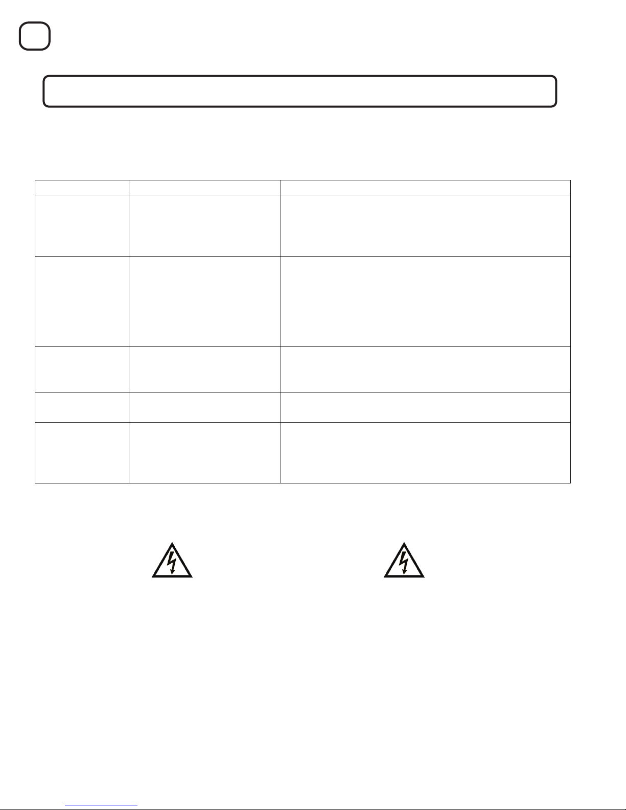
When powered on, Neurio will play the following tones to indicate its status in sequential order:
After installing Neurio and before the homeowner has connected it to the WiFi network:
If Neurio is conneced to the WiFi network, you should also hear a long chime one minute after the short chime.
Installation Validation
9
Tone
Indicaon
Descripon
Short Beeps
Voltage Check
One beep for each voltage wire that is connected.
For 3-phase installaons, there should be 3 beeps to
indicate that the black, red, and blue wires are all
connected.
Falling Tone
Voltage Warning
(condional)
Indicates that two or more of Neurio’s voltage wires
are connected to breakers on the same phase.
For 3-phase installaons, this tone is a sign of an
installaon problem. At least one of Neurio’s voltage
wires must be moved to a different breaker because it is
on the same phase another of Neurio’s voltage wires.
Short Chime
Neurio’s WiFi Network
Started
Neurio has started hosng its own WiFi network. The
homeowner can join this network to configure Neurio
and connect it to the homeowner’s own WiFi network.
Long Chime
Neurio Join Network
Succeeded
Neurio successfully joined the homeowner’s WiFi
network.
Falling Tone
Neurio Join Network Failed
Neurio was unable to join the homeowner’s WiFi
network. Neurio will now start hosng its own WiFi
network again to allow the homeowner to re-connect
to Neurio and re-enter the WiFi credenals.
Other manuals for W1
1
Table of contents
Other Neurio Accessories manuals


