Sentec WS303U User manual
"
!
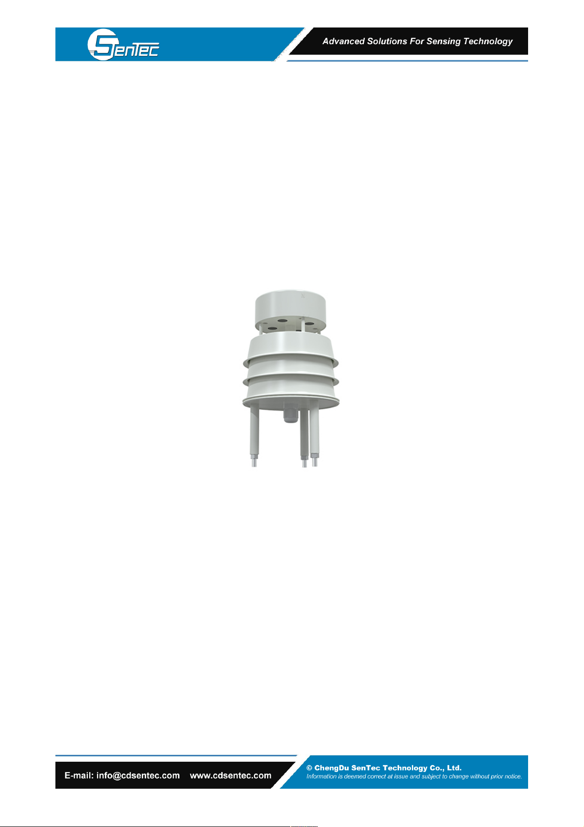
WS303U Ultrasonic Wind Speed & Direction Sensor
Product Manual
!
WORKING PRINCIPLE
Ultrasonic wind measurement is an application of ultrasonic detection technology in the gas medium. It uses the
influence of air flow (wind) on the propagation speed of ultrasonic in the air to measure the wind speed. Compared with
the conventional wind cup or rotor anemometer, the most important feature of this method is that the whole wind
measuring system has no mechanical rotating parts and belongs to non inertial measurement, so it can accurately
measure the high frequency component of gust pulsation in natural wind.
Ultrasonic wind speed and direction transmitter uses four ultrasonic probes to send and receive ultrasonic waves in
two-dimensional plane circularly. The principle that ultrasonic waves are affected by wind speed and thus increase or
decrease is used to measure wind speed and direction.
INTRODUCTION
WS303U small ultrasonic wind speed and direction sensor is a wind speed and direction measuring instrument based
on the ultrasonic principle. It uses the acoustic pulse sent to measure the phase difference of the receiving end to
calculate the wind speed and direction. The sensor can measure the instantaneous value of wind speed and direction
at the same time. It is widely used in the fields of meteorology, ocean, environment, airport, port, laboratory, industry,
agriculture and transportation.
The equipment with built-in electronic compass no longer has the requirement of orientation during installation. It only
needs to ensure the horizontal installation. The whole machine shell is made of high-quality ABS material, which has
the characteristics of light weight, no moving parts, strong and durable.
FEATURES
•No angle limit, wind speed and direction data can be measured at the same time
•No moving parts, small wear and long service life
•The random error identification technology can ensure the low discrete error of measurement and make the output
more stable under strong wind
•Using ABS engineering plastic shell, the design is light, portable, easy to install and disassemble
•Analog signal output, 4 ~ 20mA, 0 ~ 5V, 0 ~ 10V optional
•485 communication interface, standard Modbus RTU communication protocol, communication address and baud rate
can be set, and the farthest communication distance is 2000 meters
•The equipment with built-in electronic compass can be installed horizontally without direction requirement
•No maintenance and field calibration required
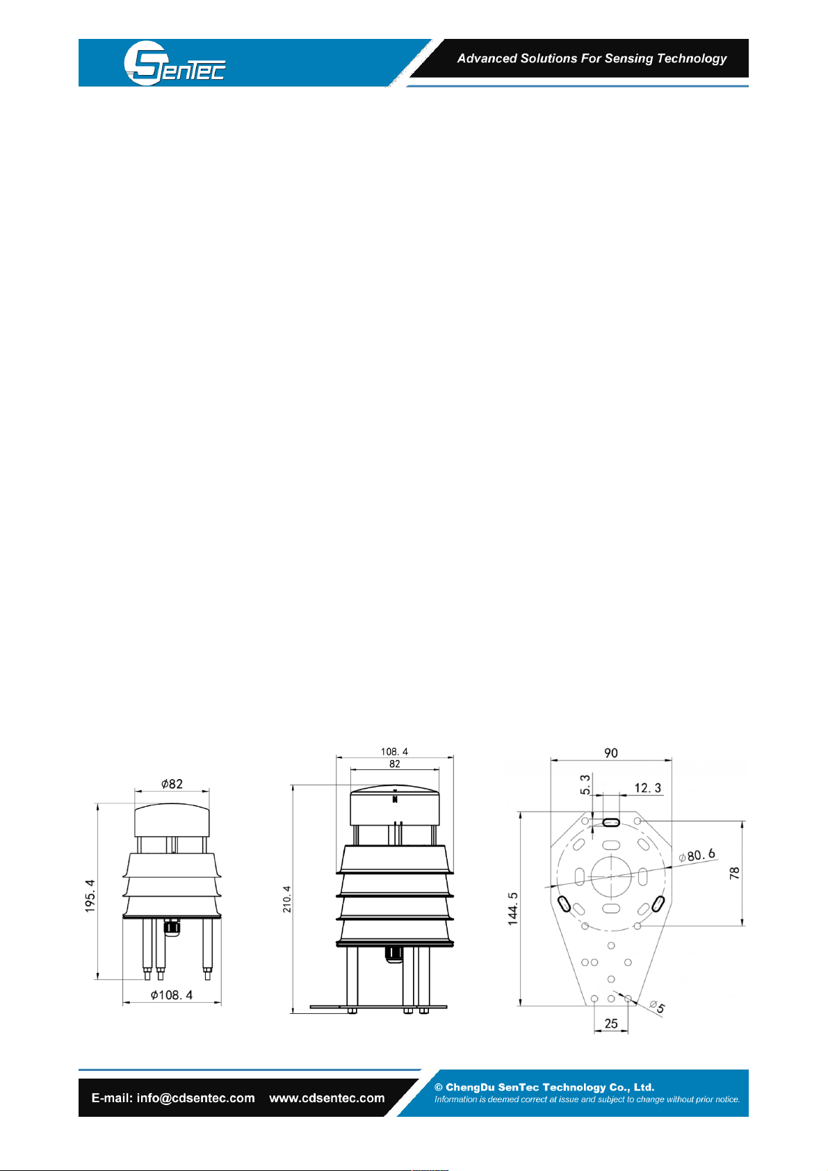
APPEARANCE SKETCH
RS485 Type
Analog Type

!
INSTALLATION INSTRUCTION
1. Inspection before equipment installation
Equipment list:
1 sensor equipment
Certificate and warranty card
One white bracket, two M4 * 10 screws and nuts, and three M5 nuts
2. Installation method
Beam installation (optional)
The installation of the device without electronic compass is shown in the figure below. The device with built-in
electronic compass only needs to be installed horizontally.
Supply voltage
10-30V DC (0-10V output is powered by 24 V)
Power consumption
485:0.12W
4~20mA/0~5V/0~10V:1.2W
Range
Wind speed
0 ~ 40m / S (customizable),0.5m starting wind speed
Wind direction
0~360°
Accuracy
Wind speed
±0.5+2%FS
Wind direction
±3°
Resolution
Wind speed
0.01 m/s
Wind direction
1°
Working environment
-40~80℃,0~95%RH
Wind resistance
75 m/s
Response time
1S
IP grade
485 type: IP65, analog type: IP54
Signal output
485 (Modbus RTU protocol)"
4 ~ 20mA current output"
0 ~ 10V, 0 ~ 5V voltage output
Load ability
Current output
≤600Ω
Voltage output
Output resistance ≤250 Ω
TECHNICAL SPECIFICATION

!
Line color
Explain
Power
brown
Power supply positive
black
Power supply negative
Output
yellow
Wind speed signal positive
white
Negative wind speed signal
blue
Wind direction signal positive
green
Negative wind direction signal
ANALOG OUTPUT
1. Interface description
Wide voltage power supply input 10-30V DC power supply. For 0 ~ 10V output equipment, the power supply is 24 v
2. Example of connection mode
sensor
sensor
Analog signal collector
Analog signal collector
4-wire wiring diagram
3-wire wiring diagram
!
RS485 COMMUNICATION OUTPUT TYPE
1. Interface description
Wide voltage power supply input 10-30V DC power supply. When connecting 485 signal line, it is noted that the two
lines a and B cannot be connected reversely, and the address between multiple devices on the bus cannot conflict.
Line color
Explain
Power
brown
Positive power supply (10 ~ 30V DC)
black
Power supply negative (GND)
Output
yellow
485-A
blue
485-B
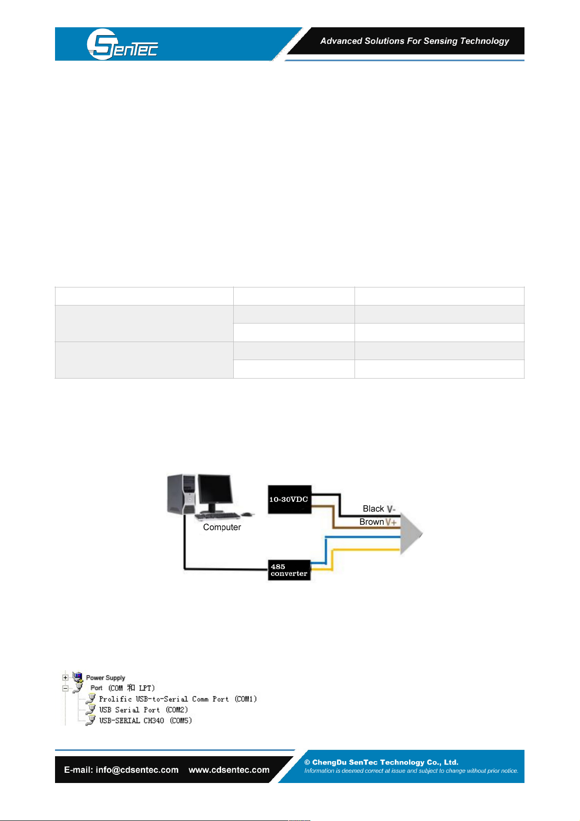
2. Installation and use of configuration software
2.1. Software selection
Open 485 data package, select "debugging software" - "485 parameter configuration software", find (Parameter
configuration tool.exe) and open it.
2.2. Equipment connection
2.3. Parameter setting
(1) Select the correct COM port (check the COM port in my computer - properties - Device Manager - port). The
following figure lists the driver names of several different 485 converters.
3. Computing method
3.1 conversion calculation of current mode output signal
The measuring range is 0 ~ 40m / s, 4 ~ 20mA output. When the output signal is 12mA, the current wind speed is
calculated. The span of wind speed range is 40m / s, which is expressed by 16mA current signal. 40m / S / 16mA =
2.5m/s/ma, that is, the current changes 1mA, and the wind speed changes 2.5m/s. Then the measured value can be
calculated. The measured value 12ma-4ma = 8Ma. 8Ma * 2.5m/s/ma = 20m / S, and the current wind speed = 20m / s.
3.2 calculation of voltage mode output signal conversion
The measuring range is 0 ~ 40m / s. take 0-10V output as an example, when the output signal is 5V, the current wind
speed is calculated. The span of wind speed range is 40m / s, which is expressed by 10V voltage signal. 40m / S / 10V
= 4m / S / V, that is, every 1V change of voltage corresponds to 4m / s change of wind speed. The measured value is
5v-0v = 5V. 5V*4/m/s/V=20m/s。The current wind speed is 20m / s.
Table of contents
Other Sentec Accessories manuals


