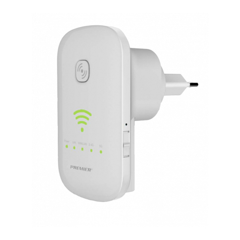
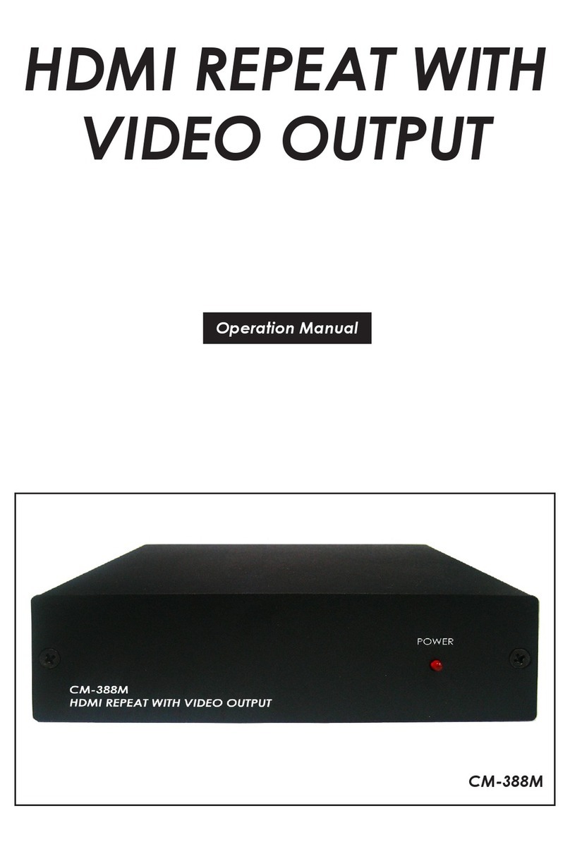
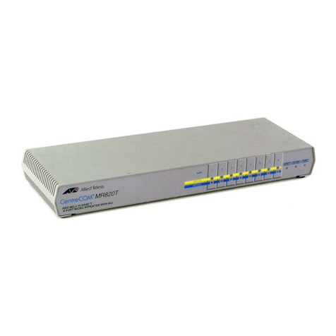
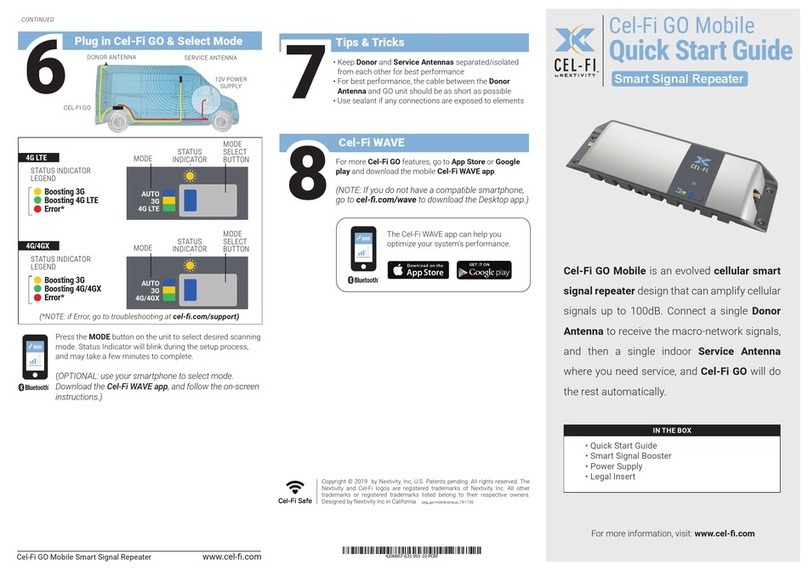
Neurona AX821 User manual

AX821 ConnectedLife
User's Manual
AX821 ConnectedLife
Wi-
Fi Booster
User's Manual
Fi Booster

2
Table of Content
1.
IMPORTANT INFORMATION ...........................................................................................1
1.1.
I
MPORTANT
S
AFETY
N
OTES
...........................................................................................1
2.
INTRODUCTION...............................................................................................................2
2.1.
P
ACKAGE
C
ONTENT
......................................................................................................3
2.2.
P
RODUCT
O
VERVIEW
....................................................................................................4
2.3.
B
UTTONS AND
LED
S
....................................................................................................4
3.
HARDWARE INSTALLATION ..........................................................................................5
3.1.
A
PPLICATION
1
–
W
I
-F
I
R
ANGE
E
XTENDER
.....................................................................5
3.2.
A
PPLICATION
2
–
F
ULL
H
Y
-F
I
N
ETWORKING
...................................................................7
4.
ENCRYPTED PLC NETWORK.........................................................................................7
4.1.
C
REATE AN
E
NCRYPTED
PLC
N
ETWORK
G
ROUP
............................................................7
4.2.
R
EMOVE
D
EVICE FROM AN
E
XISTING
N
ETWORK
G
ROUP
..................................................9
4.3.
C
REATE
A
DDITIONAL
E
NCRYPTED
N
ETWORK
..................................................................9
5.
ADVANCED WI-FI SETTINGS VIA WEB BROWSER....................................................10
5.1.
G
ETTING
S
TARTED
.....................................................................................................10
5.2.
L
OG IN TO THE
S
ETTING
P
AGE
.....................................................................................12
5.3.
H
OME
........................................................................................................................13
F
OR CONFIGURATION IN THE HOME
,
TAKE THE FOLLOWING STEPS
: ............................................13
5.3.1.
S
ELECT
L
ANGUAGE
................................................................................................13
5.3.2.
S
ETUP
W
IZARD
.......................................................................................................13
5.3.3.
O
PERATION
M
ODE
..................................................................................................14
5.4.
H
Y
-F
I
N
ETWORKING
S
ETTINGS
....................................................................................16
5.4.1.
H
YBRID
N
ETWORK
S
ETTING
.....................................................................................16
5.4.1.1.
H
YBRID
A
UTO
C
ONFIGURATION
.................................................................................16
5.4.1.2
H
YBRID
M
ANUAL
C
ONFIGURATION
...........................................................................17
5.4.2
P
OWERLINE
S
ETTINGS
............................................................................................19

3
5.4.3
H
Y
-F
I
A
UTO
-C
ONFIGURATION
..................................................................................19
5.5
I
NTERNET
S
ETTINGS
...................................................................................................20
5.5.1
LAN
(L
OCAL
A
REA
N
ETWORK
S
ETTINGS
) ................................................................20
5.6
W
IRELESS
S
ETTINGS
..................................................................................................21
5.6.1
B
ASIC
(B
ASIC
W
IRELESS
S
ETTINGS
) ........................................................................21
5.6.2
A
DVANCED
(A
DVANCE
W
IRELESS
S
ETTINGS
) ............................................................22
5.6.3
S
ECURITY
(W
IRELESS
S
ECURITY
/E
NCRYPTION
S
ETTINGS
) .........................................23
S
ECURITY
M
ODE
:
C
HOOSE ONE FROM THE OPTIONS
. ...............................................................23
5.6.4
WPS
(W
I
-F
I
P
ROTECTED
S
ETUP
) ............................................................................26
5.6.5
S
TATION LIST
..........................................................................................................28
5.6.6
S
ITE
S
URVEY
(AP
M
ODE
S
ITE
S
URVEY
) ...................................................................28
5.6.7
MAC
F
ILTER
..........................................................................................................28
5.6.8
AP
C
LONE
.............................................................................................................29
5.7
A
DMINISTRATION
........................................................................................................30
5.7.1
M
ANAGEMENT
(S
YSTEM
M
ANAGEMENT
) ...................................................................30
5.7.2
U
PGRADE FIRMWARE
...............................................................................................30
5.7.3
S
ETTINGS MANAGEMENT
.........................................................................................30
5.7.4
S
TATUS
..................................................................................................................31
5.7.5
S
TATISTICS
.............................................................................................................32
5.7.6
S
YSTEM LOG
..........................................................................................................32
5.8
C
HANNEL
N
UMBER
.....................................................................................................33
6
ENHANCE PLC PERFORMANCE .................................................................................35
7
SPECIFICATIONS ..........................................................................................................37

1
1.Important Information
1.1. Important Safety Notes
This device is intended for connection to the AC ower line. For installation instructions, refer to
the Installation section.
The following recautions should be taken when using this roduct:
•Please read all instructions before installing and o erating this roduct.
•Please kee all instructions for later reference.
•Please follow all warnings and instructions marked on the roduct.
•For safety reasons, this device should not be installed in any electric socket when being
owered on to revent the venting holes from facing the floor.
•Un lug the Powerline device from the wall outlet before cleaning.
•Use a dry cloth for cleaning. do not use liquid cleaners or aerosol cleaners.
•Do not o erates this device near water.
•This device should never be laced near or over a radiator, or heat register.
•This device relies on the building’s electrical installation for short-circuit (over current)
rotection.
•Do not allow anything to rest on the device interconnect lug.
•Do not lace this device in a location where eo le may walk on the cords.
•Because this device sends data over the ower line, it is recommended that you lug it directly
into a ower outlet.
•Do not lug the device into a UPS or ower stri with surge rotection. (The device has its
own ower filter for rotection against surges.)
•Only a qualified technician should service this device. O ening or removing covers may result
in ex osure to dangerous voltage oints.
•Un lug the device from the wall outlet and refer the device to qualified service ersonnel if
the following occurs:
-If the interconnect cords are damaged or frayed.
-If liquid has been s illed onto the device.
-If the device has been ex osed to rain or water.
-If the device does not o erate normally when the o erating instructions are followed.
-If the device exhibits a distinct change in erformance.

2
2.
Introduction
This user manual describes the AX821: ConnectedLife Wi-Fi Booster device.
The AX821 ConnectedLife i-Fi Booster is a high- erformance router and/or Wi-Fi range extender
and booster that can be lugged into any outlet in the home to create a robust Wi-Fi network. With
the increasing number of mobile, tablet, and Wi-Fi enabled Smart TVs and Blue-Ray layer devices
that stream video in the home, the demand for s eedy Wi-Fi is growing. The AX821 is designed to
be a flexible, easy-to-install device that can deliver high- erformance Wi-Fi connectivity anywhere
in the home.
Unlike traditional Wi-Fi re eaters or boosters, the AX821 combines the erformance of HomePlug
Power Line Communications (PLC) and Dual-Band 802.11abgn Wi-Fi to guarantee robust, whole
home Wi-Fi coverage. By im lementing HomePlug PLC technology, the AX821 erformance is not
affected by the construction materials used in the home (i.e. brick, concrete, metallic framing, etc),
as it uses the homes electrical wiring as a networking conduit, bringing high-s eed, wireless
Internet connectivity to locations where sim le Wi-Fi solutions cannot.
The AX821 ConnectedLife Wi-Fi Booster is also designed to revent the loss of outlet access, which
sim lifies the installation for the consumer. Additionally, the ass-through lug uses advanced noise
filtering to ensure that the device’s erformance is not im acted when even the noisiest of devices
are lugged into the AX821's re licated ower outlet.
Through the im lementation of SmartLink™ technology, the AX821 enhances erformance and
home coverage by leveraging all three electrical wires—line, neutral and ground. This new offering
increases overall network erformance by u to 50% when com ared to HomePlug solutions that
only utilize the line and neutral wires. The result is a more robust Internet connection that can be
accessed anywhere in the home.
The AX821 is com liant with HomePlug AV S ecification standard and is equi ed with 128-bit AES
encry tion to kee data secure.

2.1. Package Content
Before starting the installation of
the d
items:
AX821
Device
Accessories RJ-
45 Cable x 1
AX821 ConnectedLife
Wi-
Fi Booster
3
the d
evice
, lease make sure the ackage contains the following
AX821
AX821-BX (Bundle)
45 Cable x 1
RJ-
45 Cable x 2
AX821 ConnectedLife
Fi Booster
AX821 ConnectedLife
Wi-Fi Booster
AX821 ConnectedLife
Wi-
Fi Booster
, lease make sure the ackage contains the following
BX (Bundle)
45 Cable x 2
AX821 ConnectedLife
Fi Booster

2.2. Product Overview
AX821 ConnectedLife i-
Fi Booster
2.3. Buttons and LEDs
Image Label
A
ON
: Power on and ready.
Blinking
OFF
: Power off.
B
ON
: PLC connection detected.
Blinking
1.
Fast
2.
Normal
3.
Slow
OFF
: No PLC connection detected.
(They are too far to communicate or it is alone in its logical network).
C
Steady Green
Flash Green
Steady Red
Flash Red
Blinking
OFF:
Wi
Ethernet
Port
C
B
A
AC
Pass
-
through Socket
D
4
Fi Booster
LED
: Power on and ready.
Blinking
: PLC grou airing.
: Power off.
: PLC connection detected.
Blinking
:
Fast
: Powerline data rate > 60Mb s
Normal
:60Mb s > Powerline data rate > 10Mb s
Slow
: 10Mb s > Powerline data rate
: No PLC connection detected.
(They are too far to communicate or it is alone in its logical network).
Steady Green
: Wi-Fi network with security rotection.
Flash Green
: Wi-
Fi network traffic in transaction with security rotection.
Steady Red
: Wi-Fi network without security rotection.
Flash Red
: Wi-
Fi network traffic in transaction without security rotection.
Blinking
Green (0.5 sec ON / 0.5 sec OFF): WPS negotiation.
Wi
-Fi disabled.
through Socket
G
H
(They are too far to communicate or it is alone in its logical network).
Fi network traffic in transaction with security rotection.
Fi network traffic in transaction without security rotection.
E
F
G

D
ON:
Ethernet
Blinking
OFF:
No
E
Power Button
Push to ower on/off the device.
F
AP Clone by default. The function follows O eration Mode setting in WPS
configuration.
G
Press 10 seconds
Randomly g
Press
1
Start aring with the other PLC device. Paring rocedure kee s for 2
ends automatically when they are aired. It can be sto ed manually by ressing
the button for 1 to 3 seconds again.
H
Reset
Button
Press 1 second
Press the button when the device is owered (not in standby
3.
Hardware Installation
The AX821 ConnectedLife Wi-
Fi Booster
lays in the home network,
with littl
automatically determine if it needs
extender to boost the Wi-
Fi signal of the existing home router.
In many of today's connected homes, Wi
which tends to be over-
crowded with access oints, ul
AX821, when connected to this router over a sim le Ethernet connection, can o erate in the
5GHz band, creating a dual-
band, dual concurrent Wi
streaming video quality to mobile and tablet devices.
The AX821 will dynamically determine its role in the connected home network.
Examples of these roles are provide below:
3.1. Application 1 – i-Fi
Range Extender
Install the AX821-B
bundle to extend the existing home routers Wi
Quick Installation:
In this exam le, an AX501 is connected to the existing home router, and the
5
Ethernet
connection detected.
Blinking
: Network traffic in transaction.
No
Ethernet connection detected.
Buttons
Push to ower on/off the device.
AP Clone by default. The function follows O eration Mode setting in WPS
configuration.
Press 10 seconds
:
Randomly g
enerate a new PLC network grou name.
1
to 3 seconds:
Start aring with the other PLC device. Paring rocedure kee s for 2
ends automatically when they are aired. It can be sto ed manually by ressing
the button for 1 to 3 seconds again.
Press 1 second
: Reset to factory default setting.
Press the button when the device is owered (not in standby
mode)
Hardware Installation
Fi Booster
intelligently auto-configures
itself based on
with littl
e to no consumer intervention. S ecifically, t
automatically determine if it needs
to act as the home router itself, or as a Wi-
Fi range
Fi signal of the existing home router.
In many of today's connected homes, Wi
-
Fi routers are limited to o erating in the 2.4
crowded with access oints, ul
timately limiting erformance.
AX821, when connected to this router over a sim le Ethernet connection, can o erate in the
band, dual concurrent Wi
-Fi network whic
h can deliver robust
streaming video quality to mobile and tablet devices.
The AX821 will dynamically determine its role in the connected home network.
Examples of these roles are provide below:
Range Extender
bundle to extend the existing home routers Wi
-Fi coverage.
In this exam le, an AX501 is connected to the existing home router, and the
AP Clone by default. The function follows O eration Mode setting in WPS
Start aring with the other PLC device. Paring rocedure kee s for 2
minutes or
ends automatically when they are aired. It can be sto ed manually by ressing
mode)
itself based on
the role it
e to no consumer intervention. S ecifically, t
he device can
Fi range
Fi routers are limited to o erating in the 2.4
GHz band,
timately limiting erformance.
The
AX821, when connected to this router over a sim le Ethernet connection, can o erate in the
h can deliver robust
The AX821 will dynamically determine its role in the connected home network.
In this exam le, an AX501 is connected to the existing home router, and the

AX821 is laced in a remote location within the home where Wi
the existing router
is oor or non
clones a WPS (Wi-
Fi Protected Setu )
security credenti
als with the ush of a button.
devices to seamlessly roam between the home rou
Wi-Fi without the
need for manual intervention.
su ort WPS, then a web browser on a mobile, tablet, or PC can be used to
configure the AX821.
6
AX821 is laced in a remote location within the home where Wi
-
Fi coverage from
is oor or non
-existent.
The AX821's EasyConnect feature
Fi Protected Setu )
-enabled home router's Wi-
Fi SSID and
als with the ush of a button.
This allows mobile and tablet
devices to seamlessly roam between the home rou
ter's Wi-
Fi and the AX821's
need for manual intervention.
If the home router does not
su ort WPS, then a web browser on a mobile, tablet, or PC can be used to
Fi coverage from
The AX821's EasyConnect feature
Fi SSID and
This allows mobile and tablet
Fi and the AX821's
If the home router does not
su ort WPS, then a web browser on a mobile, tablet, or PC can be used to

3.2.
Application 2 –
Full Hy
The AX821, when combined with a second AX821 (i.e. AX821
robust home networking solution in the industry due to
technology.
Quick Installation:
In this exam le, the first AX821 is connected to
second AX821 is laced in a remote location within the home where Wi
coverage from the existing router i
of Hy-
Fi, the two AX821 devices will auto
res ective roles in the network.
Hy-Fi Extender, or Hy-
Fi Client
how the devices need to work with each other to create the most robust network
ossible.
4.
Encrypted PLC Network
4.1.
Create an Encrypted PLC Network Group
The
AX821 ConnectedLife Routers/Extenders
Every ‘HomePlug AV’ com liant PLC device that has the same default network name,
“
HomePlug AV
”, is ca able of communicating with other “HomePlug AV” devices. This is the
so-called
“Public Network
”. This allows two or more P
can communicate with one another.
7
Full Hy
-Fi Networking
The AX821, when combined with a second AX821 (i.e. AX821
-
BX Bundle) will create the most
robust home networking solution in the industry due to
the
su ort of Qualcomm
In this exam le, the first AX821 is connected to
the existing home router, and the
second AX821 is laced in a remote location within the home where Wi
coverage from the existing router i
s oor or non-existent.
Thanks to the su ort
Fi, the two AX821 devices will auto
-
configure themselves based on
res ective roles in the network.
The su orted configurations are
Hy
Fi Client
. The Hy-
Fi software will automatically deter
how the devices need to work with each other to create the most robust network
Encrypted PLC Network
Create an Encrypted PLC Network Group
AX821 ConnectedLife Routers/Extenders
are com liant with
HomePlug AV s ecification.
Every ‘HomePlug AV’ com liant PLC device that has the same default network name,
”, is ca able of communicating with other “HomePlug AV” devices. This is the
”. This allows two or more P
owerl
ine devices under the same network
can communicate with one another.
BX Bundle) will create the most
su ort of Qualcomm
Hy-Fi
the existing home router, and the
second AX821 is laced in a remote location within the home where Wi
-Fi
Thanks to the su ort
configure themselves based on
their
Hy
-Fi Router,
Fi software will automatically deter
mine
how the devices need to work with each other to create the most robust network
HomePlug AV s ecification.
Every ‘HomePlug AV’ com liant PLC device that has the same default network name,
”, is ca able of communicating with other “HomePlug AV” devices. This is the
ine devices under the same network

If you have a air of P
owerline device
ressing the GROUP button
for more than 10 seconds,
(different from HomePlug AV). Users can take the following two ste s to change the ublic
network grou to a
rivate network grou to rotect their data while transmitting over the
owerline. Users also can create m
button directly without any
software installation required.
*NOTE: Placing the devices side-by-
side will be more convenient during the setting rocedure. After
grou is set, the device
s can be de loyed
Step I: Clear Group Attribute
Clear the original network grou of device B by ressing
seconds until all
LED lights simultaneously turn
name has be
en changed to a random name. This
assigned another network name
can join a
private network group.
Step II: Join to Other Network Group
1.
Pres
s GROUP button of device A for 2 to 3 seconds (make sure POWER LED starts
blinking).
2.
Press GROUP button of device B for 2 to 3 seconds (make sure POWER LED starts
blinking).
Device B,
which has cleared its grou attribute
ste ensures that
device A and B are
device C can be added into device A’s logical network by
able to assign as many P
owerline
SPECIFICATION section.
*NOTE:
It does not matter which device’s button is ressed first, but lease ress the second device’s GROUP
button
within two minutes
after ressing first device’s GROUP
communicating with device A.
8
owerline device
s
, either one in the air can be “device A” or “device B”. By
for more than 10 seconds,
it will generate a random network grou
(different from HomePlug AV). Users can take the following two ste s to change the ublic
rivate network grou to rotect their data while transmitting over the
owerline. Users also can create m
ore than one rivate network grou
by ressing GROUP
software installation required.
side will be more convenient during the setting rocedure. After
s can be de loyed
anywhere in the home.
Clear the original network grou of device B by ressing
the GROUP button
for
LED lights simultaneously turn
off and on one time. Now
, its network grou
en changed to a random name. This
means that this device is (
assigned another network name
or
(2) ready to be used as a seed device so
other PLC devices
private network group.
Step II: Join to Other Network Group
s GROUP button of device A for 2 to 3 seconds (make sure POWER LED starts
Press GROUP button of device B for 2 to 3 seconds (make sure POWER LED starts
which has cleared its grou attribute
, will join to the Device A,
whi
device A and B are
both
under the same encry ted network.
device C can be added into device A’s logical network by
following the same ste s. The u
owerline
devices into the logical network grou as
It does not matter which device’s button is ressed first, but lease ress the second device’s GROUP
after ressing first device’s GROUP
button. After 10 seconds, device will start
, either one in the air can be “device A” or “device B”. By
it will generate a random network grou
(different from HomePlug AV). Users can take the following two ste s to change the ublic
rivate network grou to rotect their data while transmitting over the
by ressing GROUP
side will be more convenient during the setting rocedure. After
the network
for
more than 10
, its network grou
means that this device is (
1) ready to be
other PLC devices
s GROUP button of device A for 2 to 3 seconds (make sure POWER LED starts
Press GROUP button of device B for 2 to 3 seconds (make sure POWER LED starts
whi
ch has not. This
under the same encry ted network.
An additional
following the same ste s. The u
ser is
devices into the logical network grou as
allotted in the
It does not matter which device’s button is ressed first, but lease ress the second device’s GROUP
button. After 10 seconds, device will start

9
4.2.
Remove Device from an Existing Network Group
If you would like to remove Powerline device from an existing network grou , generate a new
grou name (referring to Ste I) to sto communication with an existing network grou .
4.3.
Create Additional Encrypted Network
If you want to create an additional rivate network for your ower line devices that co-exist
with your existing Powerline rivate network grou , lease re eat Steps 1-2 to generate a new
rivate network grou for selected Powerline devices.
NOTE: Users can ress the RESET button to reset the network name back to its factory default.

10
Default username: root
Default password: root
5.
Advanced i-Fi Settings via EB Browser
5.1. Getting Started
To set u advanced Wi-Fi features such as an SSID or assword, lease connect to AX821 via
Ethernet or wireless connection, and log in to the setting age through a web browser.
Before logging in to the settings age, the PC or mobile device should be in the same subnet as
this device. To do so, lease manually change the PC or mobile's IP address.
Go to "Network Connections" - "Local Area
Connection" "Connection Status" and choose the
Internet Protocol (TCP/IP) and click on
"Properties".

11
Enter IP address such as 192.168.1.XXX
(XXX can be set from 1-128) and click OK
Go to "Settings" - "Wi-Fi" - "Selected SSID" -
"Advanced settings", then click on "Static" to enter IP address
such as 192.168.1.XXX. (XXX can be set from 1-128) and
Subnet Mask 255.255.255.0
Go to "Settings" - "Wi-Fi" – Press and Hold -
"Selected SSID" to modify network - then
click on "Show advanced options".
Click "IP settings" to choose "Static" to enter
address such as 192.168.1.XXX.
(XXX can be set from 1-128)

12
5.2. Log in to the Setting Page
Step 1 Step2
O en the web browser and ty e in
IP address 192.168.1.2
(the IP of this device).
Step 3
The AX821 setting age will be
dis layed after a successful login. Then, you can
start configuring all necessary settings from
here.
Note: After com leting all necessary configurations, DO NOT forget to change the PC or
mobile device's IP address back to your original setting.
When you see the login window, enter
"root" in both the user name and
password fields.
Note: you can change user name and

5.3. Home
For configuration in the home, take the following ste s:
5.3.1. Select Language
Currently, English
is only the available
5.3.2. Setup izard
The setu Wizard assists you
in setting u
settings. To do this, click “
SETUP WIZARD
wizard will then
guide you through
Step 1
:
::
:
Set u account and assword configuration for device
Step 2
:
::
:
Set u LAN interface.
Step 3
:
::
:
The age is for basic wireless setting to set network mode
Step 4
:
::
:
Set u
wireless security and encry tion to revent unauthorized access.
Step 5
:
::
:
Click “Finish
” button and
13
For configuration in the home, take the following ste s:
is only the available
o tion in the language setting.
in setting u
the device with the minimum
amount of
SETUP WIZARD
” on the left anel. Then, click the
“Next” button.
guide you through
the required settings.
Set u account and assword configuration for device
login.
The age is for basic wireless setting to set network mode
, SSID, etc.
wireless security and encry tion to revent unauthorized access.
” button and
the device will reboot to a ly the changes.
amount of
required
“Next” button.
The
wireless security and encry tion to revent unauthorized access.

14
5.3.3.
Operation Mode
This device su orts five o eration modes for the IP network. Click to select one from the
following o tions and then click the “Apply” button.
AP Mode
The device acts as Wireless Access Point (AP) for wireless clients, and rovides connections to
Ethernet and PLC.
Client Mode
This mode enables the establishment of connection to the other AP by using infrastructure
/Ad-hoc networking ty es. With bridge o eration mode, you can directly connect the wired
Ethernet ort to your PC and the device will become a wireless ada ter.
DS (Root AP)
The wireless radio device serves the other AP by roviding a connection to a wired LAN (the
other AP must use the same chi set as this device).
DS + AP Mode
This mode combines WDS mode with AP mode, allowing WDS connections and ensuring that

15
wireless clients can survey the device.
DS Mode
WDS is used to create a network of APs that can be used as one single “virtual” AP. To do so, the
device forwards the ackets to another AP with WDS functionality. When this mode is selected,
all wireless clients cannot survey or connect to the device. The device only allows the WDS
connection in WDS mode.

5.4.
Hy-
Fi Networking Settings
5.4.1.
Hybrid Network Setting
5.4.1.1. Hybrid Auto Configuration
Qualcomm Hy-Fi
Auto Configuration is enabled by default.
automatically configure themselves into a
Extender
(HRE) de ending on network to ology.
Configuration setting.
This can be ex laine
1.
Device starts u as a HC by default.
2.
If the device is directly connected to a gateway (detected through DHCP messages), it will
convert itself to an HR.
3. If not
, then the device (HC) detects whether any devices are connected to its Ethernet interface.
If not
, the device becomes a HRE. If yes, the HC status
16
Fi Networking Settings
5.4.1.1. Hybrid Auto Configuration
Auto Configuration is enabled by default.
Under this mode, devices
automatically configure themselves into a
n Hy-Fi Router(HR), Hy-
Fi Client(HC) or Hy
(HRE) de ending on network to ology.
Please refer to Figure 5-1
for th
This can be ex laine
d in the following ste s:
Device starts u as a HC by default.
If the device is directly connected to a gateway (detected through DHCP messages), it will
, then the device (HC) detects whether any devices are connected to its Ethernet interface.
, the device becomes a HRE. If yes, the HC status
remains.
Under this mode, devices
Fi Client(HC) or Hy
-Fi Range
for th
is Hybrid Auto
If the device is directly connected to a gateway (detected through DHCP messages), it will
, then the device (HC) detects whether any devices are connected to its Ethernet interface.

17
Figure 5-1:
Hybrid Auto Configuration - Enable
5.4.1.2
Hybrid Manual Configuration
You can also assign the device as an HR, HC or HRE manually when Hybrid Auto Configuration
mode is disabled by setting Hybrid Auto Configuration to Disable. Please refer to Figure 5-2 for
the setting.
Figure 5-2: Hybrid Auto Configuration - Disable
After disabling Hybrid Auto Configuration, you can manually set the device to the o tions as
shown from the dro down list shown in Figure 5-2.
1. If the Hybrid Router o tion is selected, click “Next”. You will be asked to do the following
configurations as shown from Figure 5-3 to Figure 5-6. Once done, click “Finish”. It will take
about 40 seconds to reboot the device.
Figure 5-3: LAN Settings
Figure 5-4: Basic Wireless Settings
Other manuals for AX821
1
Table of contents
