NEVADANANO MPS User manual

NNTS Proprietary Information
MOLECULAR PROPERTY SPECTROMETER (MPS )
FLAMMABLE GAS SENSOR
EVALUATION UNIT USER MANUAL
TM
TM

1
SM-UM-0001-02
Notices
SM-UM-0001-02 (062018)
Copyright © 2018 Nevada Nanotech Systems Inc. All rights reserved.
1395 Greg Street, Suite 102
Sparks, Nevada 89431
All Rights Reserved
This publication is protected by copyright and all rights are reserved. No part of it may be reproduced or transmitted by
any means or in any form, without prior consent in writing from NevadaNano.
The information in this document has been carefully checked and is believed to be accurate. However, changes are made
periodically. These changes are incorporated in the newer publication editions. NevadaNano may improve and/or change
products described in this publication at any time. Due to continuing system improvements, NevadaNano is not
responsible for inaccurate information which may appear in this manual. For the latest product updates, consult the
NevadaNano web site at www.nevadanano.com. In no event will NevadaNano be liable for direct, indirect, special
exemplary, incidental, or consequential damages resulting from any defect or omission in this document, even if advised of
the possibility of such damages.
In the interest of continued product development, NevadaNano reserves the right to make improvements in this document
and make the products it describes at any time, without notices or obligation.
The Molecule logo is a trademark of Nevada Nanotech Systems Inc. Use of the logos for commercial purposes without the
prior written permission of NevadaNano may constitute trademark infringement and unfair competition in violation of
federal and state laws.
NevadaNano, the Molecule logo, Molecular Property Spectrometer, and MPS are trademarks of Nevada Nanotech Systems
Inc.
Other trademarks and trade names may be used in the document to refer to either the entities claiming the marks and
names or their products. Nevada Nanotech Systems Inc. disclaims any proprietary interest in trademarks and trade names
other than its own.
Please Recycle
Shipping materials are recyclable. Please save them for later use, or dispose of them appropriately.

2
SM-UM-0001-02
Table of Contents
System Overview and Setup ....................................................................................................................... 3
1.1 Kit Contents.................................................................................................................................. 3
1.2 Gas Testing Setup ........................................................................................................................4
1.3 System Setup ............................................................................................................................... 5
1.4 System Operation ........................................................................................................................ 7
Data Collection & Analysis......................................................................................................................... 10
1.5 Test Notes ................................................................................................................................... 11
1.6 Saving Data..................................................................................................................................12
General Guidelines ......................................................................................................................................13
Definitions ...................................................................................................................................................13

3
SM-UM-0001-02
System Overview and Setup
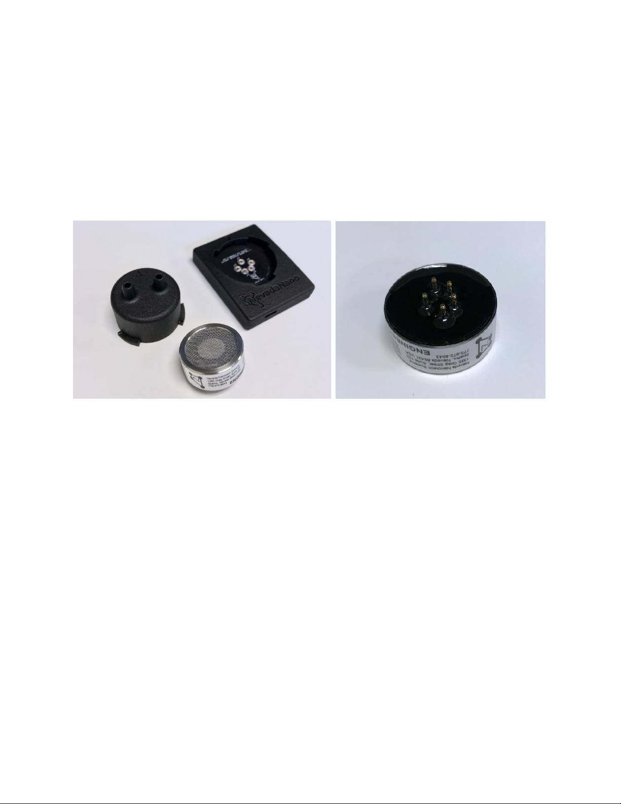
The Molecular Property SpectrometerTM (MPSTM) Flammable Gas Sensor Evaluation Unit is a user-
friendly sensor system developed for assessing flammable gas detection performance. The
evaluation system is shown in Figure 1. The sensor is 32.0 øx 13.8 mm with 1.5-mm connector pins
and connects to a provided PCB for communication with a PC (USB) or breakout to individual sensor
signals (optional 5-wire harness). The sensor contains the MPS MEMS sensing element,
environmental sensor, microprocessor, and supporting electronics inside a flame-proof housing. A
quarter-turn plastic gas mask and housing is included to provide a sealed headspace above the
sensor for test gas delivery.
Figure 1 –(a) MPS s7 Flammable Gas Sensor, housing, and gas delivery mask. (b) Sensor bottom-side detail.
1.1 Kit Contents
The complete MPS™Customer Evaluation Unit kit consists of:
MPSTM S7 flammable gas smart-sensor
MPS Sensor Interface software and drivers
Sensor PCB + housing
Gas delivery mask with integrated barbs
USB A to micro B cable
1/4” Tygon tubing (McMaster: 6516T17)
(b)
(a)

4
SM-UM-0001-02
1.2 Gas Testing Setup
The MPS measures molecular properties to determine the quantity of flammable gas present in a
sample. The system is optimized for "real-world" cases. As such, the effects of humidity,
temperature and pressure are automatically compensated out. However, sudden, wholesale
changes to the molecular properties of the sample--i.e. artificial changes which can only be
generated in a lab test rig--can lead to inaccurate MPS outputs. (This of course excludes changes due
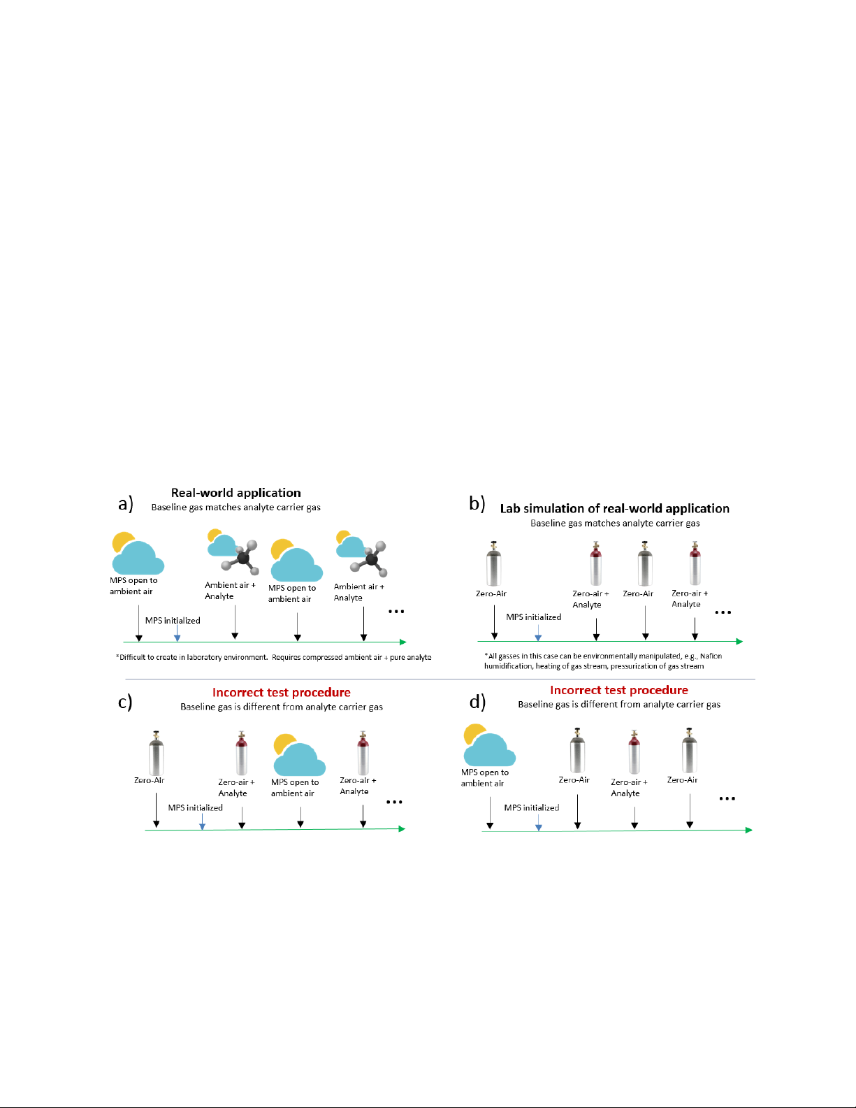
to the presence of flammable gas.) An example of an inadvisable change (shown in Fig. 2c, d) would
be alternating between ambient air (which contains argon, carbon dioxide and other trace gases)
and flammable gas + synthetic "zero air" balance (which contains none of the trace constituent
gasses in ambient air). To simulate the real-world application (Fig. 2a) in artificial laboratory testing,
the same type of “air” must be used for the background and the carrier of the flammable gas for the
duration of the test. An example of a proper protocol is shown in Fig. 2b. Using a variation of the
“incorrect” procedure will invalidate the accuracy of MPS measurements.
The best practice for performance testing in a laboratory is to use a humidified zero-air background,
followed by a switch to a humidified analyte stream with the same zero-air composition as balance
gas, then a switch back to humidified zero-air to clear the test chamber. This mimics real-world MPS
performance, where flammable gas is introduced into relatively invariant ambient air (Fig. 2a).
Figure 2 –Correct testing of MPS in (a) real-world application and (b) laboratory environments. Incorrect test
procedures are shown in (c, d). In both cases, the analyte and carrier gas are dissimilar during the test, causing
inaccurate results.

5
SM-UM-0001-02
1.3 System Setup
The MPS Flammable Gas Sensor Evaluation Unit receives power and communicates to a PC via USB,
or via UART through 5-wire harness with V+, V-, TX, RX, and Analog out (optional) connections. The
MPS Sensor Interface is used to:
establish communication with the sensor to start, pause, and end tests
examine data in real-time
record test notes
save data to .csv file
The MPS Sensor Interface and accompanying drivers are available at:
https://www.nevadanano.com/MPS-Flammable-Gas-Sensor-Support
The user should first install the FTDI Driver, followed by a system restart, and then install the MPS
Sensor Interface UI. The setup procedure follows:
1. It is recommended to always power the computer connected to the MPS since the sensor
receives its power from the computer.
2. Connect the micro-USB cable to the MPS, then connect the opposite end of the USB cable to
a USB port on the computer. The MPS will automatically receive power from the computer.
5. Using the supplied ¼ -in tubing, connect the test gas system to one of the integrated barbed
connectors on the MPS gas mask.
Test gas should be supplied to the sensor at rates no greater than 300 mL/min.
The use of Nafion
1
tubing is recommended to humidify the test gas stream.
6. Attach the gas mask to the housing by aligning the arrow on the gas mask at the 10 o’clock
position and inserting the three tabs into the housing. Turn the mask clockwise until the
arrows on the housing and mask align and the mask “clicks” into place. The barbs will be
aligned across the horizontal axis of the housing.
Figure 3 –Proper gas mask attachment is achieved when the arrow points align and the barbs are in the horizontal
position.
1
For more information on Nafion, including its permeability for various gases, refer to:
http://www.permapure.com/products/nafion-tubing/

6
SM-UM-0001-02
7. Open the MPS Sensor Interface application from the desktop icon.
8. Click the “Find MPS Devices” button and select the MPS Flammable Gas Sensor connected to
the computer (Fig. 4). The sensor name is found on the sensor serial number in the form:
B12318003.
Figure 4 –(a) Selecting the active MPS™Flammables device. (b) Sensor name indicator
9. The MPS sensor is now ready for testing. Proceed to System Operation, and read thoroughly
before continuing
(a)
(b)

7
SM-UM-0001-02
1.4 System Operation
Figure 5 shows a typical benchtop test setup. A calibrated gas cylinder (e.g., zero-air, 50%LEL
methane in air) supplies gas from a 300-mL/min regulator via Nafion tubing to the gas mask. An
example of a suitable regulator is a 70-series fixed flow regulator, which is compatible with 34, 58,
74, 103 and 116 Liter aluminum cylinders as well as 103 Liter steel cylinders. Flow can be stopped by
removing the regulator or closing the black knob. The Nafion tubing humidifies the analyte gas
stream to ambient humidity levels without appreciable loss of analyte. The experimental test area
should have adequate ventilation to avoid exposure of gasses to the user. An additional zero-air gas
cylinder should be applied to the sensor when analyte gas is not flowed.
Figure 5 –(a) Typical test setup. (b) Detail gas and PC connections.
MPS Sensor Interface Software
Nafion
tubing
Test gas
cylinder
70-series Fixed
Flow Regulator
Exhaust
tubing
MPS
Inlet
Outlet
(a)
(b)

8
SM-UM-0001-02
1.4.1 Conducting a Gas Test
1. After performing system setup (1.3), the start button will now be enabled (highlighted in
green in Fig. 6). Start the flow of zero-air baseline gas over the MPS and wait ~1 minute
before proceeding for baseline gas to replace ambient air. Click Start to begin the initial
baseline acquisition.
Figure 6 –MPS™Flammables unit ready for testing. Sensor name is populated and start button is enabled.
2. The unit will acquire 10 baseline readings (Fig. 7, highlighted in green). After this stabilization
period, the sensor is ready for testing.

9
SM-UM-0001-02
Figure 7 –Acquiring sensor environmental baselines at the beginning of a test.
3. Next, apply a test gas cylinder and note the results. A stable gas reading should be displayed
within 30 seconds of applying a test cylinder as the supplied gas mask equilibrates with the
tank concentration.
4. After removing the test-gas cylinder, reconnect to a zero-air cylinder to purge the test gas
and continue to maintain a stable environment.
5. Repeat steps 3, 4 as needed to test various gasses and concentrations. When analyte is not
tested, it is important to keep the baseline/zero-gas flowing as the MPS smart-algorithms will
periodically record baselines.
1.4.2 System Shutdown
The MPS™Flammables sensor must be in an idle state before shutdown. Pause the current test and
wait for the system status dialogue to display “Idle”, then save or clear the data. The USB cable can
now be disconnected.

10
SM-UM-0001-02
Data Collection & Analysis
During a test, the system generates a new data point every 2 seconds. Data can be visualized on the
MPS Sensor Interface in real time throughout a test. Graphs can be resized and zoomed in and out
while data are being collected. An example screenshot is shown in Fig. 8. Graphs can be reset to
auto-scale by double clicking on the desired axis.
Figure 8 –MPS™Flammables unit during testing.

11
SM-UM-0001-02
1.5 Test Notes
The user must enter test notes by clicking the “Edit Test Notes” button any time prior to saving data.
A set of example test notes is shown below.
Figure 9 –Example test notes dialogue box.
After entering the experimental test notes, click “Save Data”. A dialogue box will appear to prompt
the user to select a directory for saved test data. After saving, the user can now clear the data and
begin another test.

12
SM-UM-0001-02
1.6 Saving Data
Throughout a test, data are stored in a temporary directory. Once a test is complete, data can be
saved to a drive location specified by the user. The folder created in this step is named using the
following format.
Year_Month_Day-Time SensorName_testName
Here is an example:
2017_09_20-164411 B12218010_10_50_LEL MethaneTest
Avoid using hyphen and special characters ( - , \ , /, %, & ) when saving data:
The data folder will contain:
1. timelog.txt –This file provides the start, pause, re-start, and end times of a test. Here is an
example:
2017_09_20 - 13_03_00: Started
2017_09_20 - 16_43_47: Paused
2017_09_20 - 16_44_11: Data saved
2. mpsData.csv –This is a comma-separated-value formatted file that contains all the data from
the test, organized in columns:
Time
[s]
Cycle
[#]
Temp.,
[C]
Press.,
[kPa]
Rel. Hum.,
[%]
FlamID
Concentration
[%LEL]
3. testNotes.txt –This file provides a record of the test notes entered in the user dialogue box
before saving.

13
SM-UM-0001-02
General Guidelines
Follow all applicable lab safety procedures.
Using gas source concentrations below 100%LEL (50%LEL is common) will ensure that
flammable conditions are not created in the test setup.
Lecture bottles with gas concentrations near 50%LEL are commonly used for calibration of
gas detection instruments in the field, and do not create unsafe (flammable) or unhealthy
(toxic) gas conditions because the gases dilute quickly to safe concentrations when released
into ambient air at 300 mL/min. Nonetheless, it’s a good idea to ventilate the workspace,
especially for prolonged tests. Implement a dilution/evacuation system to avoid exceeding
the PEL.
Operate the unit within the specifications (temperature, pressure, concentration range, etc.).
Rapid changes in environmental conditions (i.e.: >10% RH or >10°C) over the course of a short
time period (< 1 min) may cause the sensor to falsely identify the environmental change as a
flammable gas. These conditions are not considered as normal use-case scenarios (i.e., they
only occur in “artificial” laboratory testing protocols) and should be avoided. Should the unit
be subjected to one of these conditions, the unit should be paused, data saved (if desired)
and cleared. Then, the system should be restarted once the environment has equilibrated.
The Nafion tubing is fragile. Avoid kinking or stressing the tubing to maintain adequate flow
to the sensor.
Definitions
LEL (Lower Explosive Limit) -- Lowest concentration (percentage) of a gas or vapor in air
capable of producing a flash of fire in the presence of an ignition source (arc, flame, heat).
Concentrations lower than the LEL are 'too lean' to burn.
PEL (Permissible Exposure Limit) –a legal limit on the amount or concentration of a substance
in the air to which a person can be exposed.

SM-UM-0001-02
Nevada Nanotech Systems Inc.
1395 Greg Street, Suite 102
Sparks, Nevada 89431
United States
Tel: 1-775-972-8943
Fax: 1-775-972-8078
www.nevadanano.com
Other manuals for MPS
1
Table of contents
Other NEVADANANO Accessories manuals
Popular Accessories manuals by other brands

Tripp Lite
Tripp Lite UPB-10K4-S2U owner's manual

home & CO
home & CO TT-1101XQ instruction manual

elsner elektronik
elsner elektronik Vari KNX 3L-TH-D GPS Installation and adjustment

Philips
Philips PAR20 Specifications

Carefree of Colorado
Carefree of Colorado VACATION'R owner's manual

Imetec
Imetec N1701 operating instructions