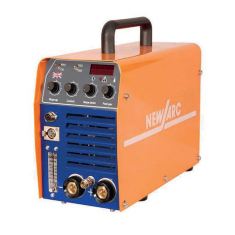
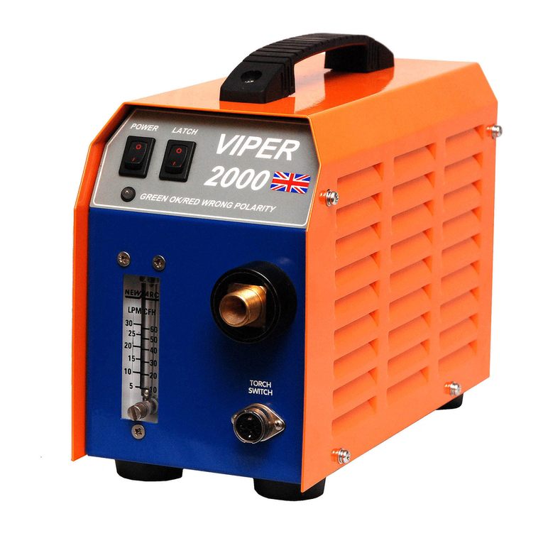
NewArc Viper2000 User manual

Processes
Description
To maintain continued developments of our products we reserve the right to alter specifications as quoted without prior notice
Newarc Ltd.
UK‘s Leading Manufacturer Of Welding quipment
Newcastle +44 (0) 191 295 0111
Aberdeen +44 (0) 1224 771 063
www.newarc.co.uk
Viper2000
INSTRUCTION MANUAL
03/14
TIG unit
Important Information
All persons authorised to use, repair or service the VIPER2000 tig
unit, should read the section on safety, before any work is under
taken. Further information is available in publication HSG118
'Electric safety in arc welding', which may be obtained from the
Health & Safety Executive. Please contact your distributor should
you not understand any of the information within this document.


VIPER2000
3
TABLE OF CONTENT
ECTION 1 — AFETY
1.1 Servicing Hazards _________________________________________________________ 4
ECTION 2 — PECIFICATION
2.1 - Description_______________________________________________________________ 5
ECTION 3 — IN TALLATION
3.1 - Connecting to the Power Source_________________________________________ 5
3.2 - Connecting the Gas Hose________________________________________________ 5
ECTION 4 — OPERATION
4.1 - Front Panel Controls____________________________________________________ 6
4.2 - Gas Controls__________________________________________________________ 6
4.3 - Contactor_____________________________________________________________ 6
4.4 - Arc Initiation___________________________________________________________ 6
ECTION 5 — FAULT FINDING AND MAINTENANCE
5.1 - Maintenance__________________________________________________________ 7
5.2 - Fault Finding___________________________________________________________ 7
ECTION 6 — ELECTRICAL DIAGRAM
6.1 - System Diagram________________________________________________________ 8
ECTION 7—PART BREAKDOWN
7.1 - Component Locations__________________________________________________ 9
7.2 - Parts List_______________________________________________________________ 10

VIPER2000
4
ECTION 1 — AFETY
1.1 ervicing Hazards
Fire and Explosions
Pay attention to fire and safety regulations in force at the
welding site.
•
Remove all flammable or combustible materials from the
welding area and the immediate vicinity.
•
Suitable fire fighting equipment must always be present
where welding is undertaken.
•
Be aware that a fire risk is present for a considerable time
after welding operations have ceased because of sparks
and hot slag etc. Take suitable precautions when you
have finished welding.
•
Take care when welding containers that have held flam-
mable or combustible material, these should have been
specially cleaned before being made available to the
welder. If in doubt do not proceed.
Burns
Be aware that burns may be the result of the heat involved in
the welding process, welding spatter or the Ultra Violet Ra-
diation given off by the arc itself.
•
Wear suitable flame retardant clothing over all your body.
•
Wear protective gauntlets designed for welding use.
•
Wear a welding facemask fitted with the correct filter
shade suitable for the current at which you will be weld-
ing.
•
Avoid wearing oily or greasy clothing as a spark may ig-
nite them. Where possible ensure that a suitable first aid
kit and a first aid person qualified in the treatment of
burns are available nearby.
Fumes
Welding operations give off harmful fumes that are hazard-
ous to your health.
•
Make sure the welding area is well ventilated. Use suit-
able fume extractors or exhaust fans if necessary.
•
If the ventilation is not suitable then breathing apparatus
may have to be used.
•
Do not weld plated metals or metals which contain Lead,
cadmium, Zinc, Mercury or Beryllium unless you are wear-
ing breathing apparatus approved for the purpose.
Electric hock
•
Do not touch live electrical parts.
•
Do not work in wet or excessively humid areas.
•
Avoid touching the work piece whilst welding.
•
Keep your clothing and body dry.
The safe handling of gas cylinders
The VIPER2000 TIG units use argon gas during TIG welding. This is
an inert gas and can displace oxygen in the atmosphere lead-
ing to asphyxiation.
•
Note! Gas cylinders are under pressure and can explode
if punctured. Please ensure the cylinder is secured in a
stable location away from any heat source or potential
mechanical damage.
•
Always place gas cylinder on the rear shelf of the power
source and securely fasten it using securing chain sup-
plied, if it is not desired or possible to place the cylinder
on the cylinder carrier of the power source then the cylin-
der must be securely fastened to a wall or placed in a
specially designed cylinder carrier.
•
Do not use gas cylinders whose contents you are unsure
of.
•
Check the gas cylinder, pressure regulator and gas hoses
regularly for leaks and discard any suspect item.
•
Do not connect directly to a gas cylinder without using a
pressure-reducing regulator designed for use with argon.
•
Always install and use pressure regulators in accordance
with the manufacturers instructions
•
It is advisable when attaching the regulator to the gas
cylinder to briefly turn on the cylinder valve to expel any
foreign objects that may be present. These may later
block the solenoid valve of the machine if not dealt with.
Turn your face away from the cylinder valve when under-
taking this action.
•
Always turn off the valve on the gas cylinder when you
have finished welding.
Further information is available in publication H G118 'The safe
use of compressed gases in welding, flame cutting and allied
processes' which may be obtained from the Health & afety Ex-
ecutive.
Welding and earth return cables
•
arth return and electrode holder cables must have a
cross sectional area of at least 35mm
2
.
•
Only use copper cables, the use of Aluminium cables
may have a detrimental effect on the performance of
the machine.
•
Regularly inspect welding cables and connectors for
wear abrasion and corrosion. Corroded cables and con-
nectors may overheat and become a fire hazard.
•
nsure that all welding connectors are fully mated, the
connectors should be pushed fully home and then turned
clockwise to lock. If the connectors are not mated fully
then they may overheat and become a fire hazard.
•
If possible, fasten the earth return clamp directly to the
job to be welded and ensure that the surface is free from
rust and paint.
VIPER2000
5
ECTION 2 — PECIFICATION
2.1 - Description
The Viper 2000 is a compact D.C. TIG arc ignition unit providing contactor, gas timing and high fre-
quency arc initiation facilities. The Viper 2000 uses state of the art electronics and microprocessor
technology. It is rugged and reliable and is built to withstand typical site conditions. The Viper 2000
draws power from the welding cables and requires no auxiliary supply cables.
tandard features:
• Solid state arc ignition
• Contactor control of current
• Gas flow solenoid
• Torch switch latching
• Gas flow-meter option
• Reverse polarity protection
Site the Viper 2000 on a clean dry base preferably above ground level. nsure that the ventilation lou-
vers on the side of the unit are not obstructed. Protect the machine against heavy rain.
Frequently inspect the interconnection cables and welding torch and repair any defects immedi-
ately.
3.1 - Connection to Power ource
The DC TIG process uses negative torch polarity with the work piece connected to the positive outlet
of the power source. Connect the power cables as below: -
• Connect the negative cable from the power source to the bottom left connector on the rear of the
unit. (-) input
• Connect the positive cable from the power source to the bottom right connector. (+) input
• Connect the welding ground to the uppermost right connector. (+)
3.2 - Connection of the Gas Hose
A gas hose suitable for use with pure argon should be connected between the pressure reduction
regulator and the gas connection at the rear of the unit, do not over tighten!
Note: - the Viper 2000 requires a suitable flow meter to be fitted to the pressure reduction regulator.
Note: -The pressure reduction regulator should be set at approximately 5 Bar.
Technical Data
Duty Cycle 200A @ 100%
Input Voltage 40 – 100 volts D.C.
Weight (kg) 5Kg
Dimensions
Height - 210mm
Width - 127 mm
Length - 322mm
ECTION 3 — IN TALLATION

VIPER2000
6
ECTION 4 — OPERATION
4.1 Front Panel Controls
1. Power switch, the power switch disconnects the internal electronic circuitry from the welding supply
voltage. Note! The welding cables will still be live if the power source is switched on.
2. Power indicator, the power indicator will illuminate green when the power is switched on. If the
power indicator illuminates red then the welding input cables are incorrectly connected and should
be reversed. No damage will be caused if the power cables are incorrectly connected but the unit
will not work.
3. Latch switch, the latch switch switches between the two different torch switch modes. In the off posi-
tion the torch switch must be pressed and held during welding. In the on position the torch switch
may be pressed and released during welding. To stop welding the torch switch must then be pressed
and released again.
4. Flow meter, the flow meter gives an indication of gas flow and allows the gas flow rate to be ad-
justed from the front panel of the unit.
Note: - Do not over tighten the control knob as damage may occur to the flow-meter valve seat,
note that if the control knob is unscrewed too far air may enter the valve assembly and may cause
porosity or contamination of the weld.
4.2 Gas Control
Gas pre-flow, the Viper 2000 provides pre and post timing of gas flow using an internal gas solenoid. When
the torch switch is operated for the first time there will be 0.25-second purge of shielding gas before the
contactor and arc ignition circuits are energized. This initial delay is to ensure that the argon lines and
welding torch are purged of air before welding commences.
Note: - for example, if the gas is already flowing after the end of a weld then both the contactor and arc
ignition circuits will energize immediately upon pressing the torch switch.
If an arc is not struck within 5 seconds of pressing the torch switch gas solenoid, contactor and arc ignition
will be turned off, releasing the torch switch will reset the sequence.
Gas post-flow, when the torch switch is released at the end of a weld the shielding gas will continue to flow
for approximately 15 seconds to allow an inert gas shield to be present whilst the weld cools down. This
prevents oxidization of the weld pool and contamination of the tungsten electrode.
4.3 Contactor
The internal contactor allows the welding current to be switched on and off by means of the torch switch.
If the tungsten electrode is inadvertently touched into the weld pool whilst welding then the contactor will
turn off the welding current. This reduces the possibility of tungsten inclusions in the weld. To avoid further
weld pool contamination during this period shielding gas coverage is maintained until the torch switch is
released.
4.4 Arc initiation
The arc ignition system used in the Viper 2000 displays a positive arc-striking characteristic over the full input
voltage range of the unit. This excellent striking characteristic is achieved by using state of the art elec-
tronic techniques. As the arc ignition system does not require a spark gap for its operation it is virtually
maintenance free.

VIPER2000
7
ECTION 5 — FAULT FINDING AND MAINTAINANCE
5.1 Maintenance
Warning!
All electric shocks are potentially lethal. Disconnect the Viper 2000 from the power source
and wait 5 minutes for internal capacitors to discharge before removing the outer casing.
User maintenance is limited to the following items: -
Regularly clean the exterior of the unit of dust and dirt. Build up of dirt around the torch
connection may lead to high voltage tracking.
Regularly check the condition of welding cables, torch and gas hose.
Periodically clean dust and debris from the inside of the unit. This should be done using a
soft brush and vacuum cleaner. Do not use compressed air at high pressure. Try not to dis-
lodge any cable connectors while cleaning the inside of the unit.
5.2 Fault Finding
Unit appears to be dead – ensure that both power source and Viper 2000 are switched
on. If the power indictor is not lit then check for breaks in the power cables. If the power
indicator is red then the power cables need to be reversed. If the power indicator is
green then the power cables are correctly polarized.
Porosity (holes) in weld - generally caused by lack of shielding gas, but could also result
from contamination (oil, grease, paint or rust). Check for too low or too high a flow rate.
H.F. but arc will not strike – ensure that the work earth lead is connected to the positive
output connector on the rear of the machine. Check that the correct shielding gas is be-
ing used. Check for too low or too high a gas flow rate.
Unit is sluggish in operation – if the operation of the unit seems sluggish then this may be
due to a low supply voltage. Check that the supply voltage to the unit is in the range of
40 to 100 volts. Voltages outside this range may result in erratic operation or cause dam-
age to the unit.

VIPER2000
8
ECTION 6 — ELECTRICAL DIAGRAM
6.1 - ystem Diagram

VIPER2000
9
ECTION 7—PART BREAKDOWN
7.1 - Component Locations
3
1 1

VIPER2000
10
ECTION 7—PART BREAKDOWN
7.2 - Parts List
Item # Description Part no.
1 Input connector (male DIX) M00036
2 output connector (female DIX) M00037
3 Gas solenoid assembly
48V version up to serial number V0904850
24V version from V0904851 to NCL0009811
24V version from serial number NCL0009812
M90184
M90183
M90176
4 Power indicator L D M60152
5 Power switch M70050
5 Torch latching switch M70050
6 Power gas connection 3/8” BSP M00041
7 Torch switch socket M00064
8 Argon flow meter M00018
9 Flow meter control knob M00019
10 Main PCB M90473
11 Power resistor 470R M20032
12 VDR assembly M90474
13 HF bypass capacitor (3 per machine) M40076
14 Contactor M70070
15 HF inductor assembly M90479
16 Negative bus bar M90499
17 Positive bus bar M90500
19 Molded handle M00026
20 Mounting feet (4 per machine) M00096
21 Fuse 3.15 amp slow blow M00020
Torch switch plug M00063


Head Office
Newarc (Newcastle) LTD
6 Wincomblee Road
Walker Riverside
Newcastle upon Tyne
NE6 3PF
Tel: +44 (0)191 295 0111
Fax: +44 (0)191 295 0077
Website: www.newarc.co.uk
e-mail: [email protected]
Aberdeen Office
Newarc (Aberdeen) LTD
4 Howe Moss Drive
Kirkhill Industrial Estate, Dyce
Aberdeen
AB21 0GL
Tel: +44 (0)1224 771063
Fax: +44 (0)1224 724536
e-mail: [email protected]
Guarantee
Newarc Ltd warrants that its goods and services are guaranteed to meet the specific performance
under the stated conditions of use. Newarc cannot be held responsible for general wear and tear
or for failure occurring due to misuse or abuse arising out of circumstances outside the stated condi-
tions of use. The stated conditions of use are that considered normal industrial practice and are not
exhaustive. ach machine is identified with a unique serial number and accompanied with the
guarantee. Newarc reserve the right to a) Repair. b)Replace. c)Authorise the reasonable cost of
repair or replacement at an approved Newarc service agent. d)Credit for any purchased equip-
ment (less reasonable depreciation for actual use and condition) at its entire discretion. This in no
way affects your rights as a consumer. The guarantee is enclosed with each machine.
Waiver
Whilst every endeavour is made to ensure the details of this document are correct at the date of
print. Newarc accepts no liability for correctness in respect of any impending change in legislation
or health and safety requirements. Newarc also reserve the right to amend the detail of the docu-
ment content without any notification to the consumer. If reference is made to Newarc while utilis-
ing the document for spare parts purchase or instruction please advise the revision of the document
to ensure correctness of information.
Table of contents
Other NewArc Welding System manuals

NewArc
NewArc Viper2500s User manual

NewArc
NewArc R4000 Quick start guide

NewArc
NewArc R5000 CCCV User manual

NewArc
NewArc WFU12A-ILS Quick start guide

NewArc
NewArc NA9910619 Quick start guide

NewArc
NewArc R5000 CCCV User manual

NewArc
NewArc Viper 2000 Quick start guide

NewArc
NewArc R2500 User manual

NewArc
NewArc RT2000 User manual

NewArc
NewArc r1500 User manual

NewArc
NewArc rt2500 User manual

NewArc
NewArc R2500 User manual

NewArc
NewArc RT2000 Quick start guide

NewArc
NewArc Viper 2500s User manual

NewArc
NewArc Viper 2500s Quick start guide

NewArc
NewArc WFU12-4C Quick start guide

NewArc
NewArc R7000 Quick start guide

NewArc
NewArc R7000 User manual

NewArc
NewArc rt2500 Quick start guide