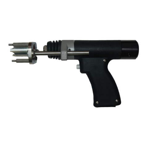
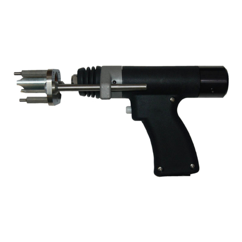
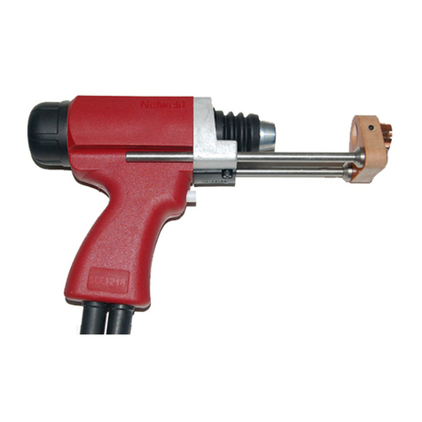
Nelson NS20A Instructions for use

NS20A & NS20N
Heavy Duty Floating Lift
Welding Guns
Instruction and
Maintenance Manual
ersion 1.30
December 2008
Manual Part Number 729-110-024

NS20A and NS20N HEAVY DUTY FLOATING LIFT WELD GUN
LIMITED WARRANTY
Nelson’s only wa anty is that goods being sold will be f ee f om defects in wo kmanship and
mate ial. This wa anty is exp essly in lieu of othe wa anties, exp essed o implied and whethe
statuto y o othe wise, including any implied wa anty of me chantability o fitness fo a
pa ticula pu pose.
Nelson’s liability fo b each of wa anty shall a ise only upon etu n of the defective goods at
Buye ’s expense afte notice to Nelson of the claimed b each, and shall be limited to fu nishing a
like quantity of such goods f ee f om such defects o , at Nelson’s option, to efunding the
pu chase p ice (less easonable dep eciation based on actual use); p ovided, howeve , that Nelson
will not accept eceipt of equipment etu ned unless buye has p eviously affo ded Nelson’s
pe sonnel a easonable oppo tunity to inspect and epai said equipment at buye ’s facility o
such othe location as is mutually ag eeable. Notice to Nelson must be given within 30 days of
such defect o failu e and within ninety (90) days f om the date the equipment was delive ed. No
compensation o eimbu sement fo t anspo tation costs of any kind will be allowed.
Please note that this wa anty does not extend beyond the o iginal egiste ed pu chase , and does
not wa ant equipment that has been modified by any pa ty othe than Nelson, o equipment that
has been imp ope ly installed, imp ope ly ope ated, o misused based upon indust y standa ds, o
equipment which has not had easonable and necessa y maintenance, o equipment which has
been used fo ope ation outside of specifications fo the equipment. Nelson shall neve be liable
fo consequential damages.
Nelson ese ves the ight to make enginee ing and/o pa t changes, at any time without notice, as
a esult of ou commitment to continuous imp ovement.

NS20A & NS20N Heavy Duty Gun Page 1 Revision 1.20 2/19/08
MANUAL CONTENTS
Gun Part Number
751-535-000 751-535-100 751-535-500 751-693-000
Control Cable Connector Cannon R&S Hubbell Hubbell
Weld Cable Connector CamLok CamLok CamLok Dinse
Note: All these guns a e equipped with a steel T anquil-A c
®
Plunge Dampene
TABLE OF CONTENTS
MANUAL CONTENTS...........................................................................................................................................................1
GUN SETUP FOR WELDING STEEL STUDS .....................................................................................................................2
Accessory Installation ........................................................................................................................................................2
Plunge Adjustment.............................................................................................................................................................2
Free Travel Adjustment .....................................................................................................................................................2
Lift Adjustment ...................................................................................................................................................................3
Nelweld Power Sources .................................................................................................................................................3
Series 4800 & Series 5000 (TR-1600)...........................................................................................................................4
Series 6000 (TR-2400) ..................................................................................................................................................4
Series 3000 (NS-20A HD)..............................................................................................................................................5
WELD INSPECTION .............................................................................................................................................................6
isual Inspection................................................................................................................................................................6
Physical Inspection ............................................................................................................................................................6
SEQUENCE OF OPERATIONS ...........................................................................................................................................7
Exploded iew ...................................................................................................................................................................8
Parts List ............................................................................................................................................................................9
MAINTENANCE INSTRUCTIONS ......................................................................................................................................10
Part Number Designation ................................................................................................................................................10
Disassembly of Gun.........................................................................................................................................................11
Examination and Cleaning of Gun Parts .........................................................................................................................12
Reassembly of Gun .........................................................................................................................................................12
Installing New Control Cables -Welding Gun #751-535-000...........................................................................................13
Installing New Control Cables -Welding Gun #751-535-100...........................................................................................13
Installing New Control Cables -Welding Gun #751-535-500 & #751-693-000................................................................13
Installing New Weld Cables -All Guns .............................................................................................................................14
DIMENSIONS AND SPECIFICATIONS..............................................................................................................................15

NS20A & NS20N Heavy Duty Gun Page 2 Revision 1.20 2/19/08
GUN SETUP FOR WELDING STEEL STUDS
Accessory Installat on
1. Inse t chuck fo 1” o smalle studs into the
chuck adapto . While holding the gun by the
chuck adapte , lightly tap the chuck with a
hamme until it is seated and held fi mly in the
tape of the chuck adapte (Figure 1). Chucks
fo studs la ge than 1” diamete sc ew onto the
½-20 th ead of the hex shaft adapte .
Note: A diffe ent Chuck is equi ed fo each
stud diamete .
2. Inse t Fe ule G ip into Foot and secu e with
setsc ews p ovided (Figure 1).
3. Inse t stud in Chuck and Fe ule in Fe ule G ip
o Fe ule Holde .
4. Loosen the sc ews holding the foot to the leg
and adjust the foot so that stud is cente ed in
the fe ule. This is important because imp ope
welds will esult if the e is binding o f iction
between the stud and fe ule. Tighten the
sc ews and echeck the cente ing.
Hex Shaft
Adaptor
Chu k
Adaptor
Chu k
Foot Ferrule
Grip
Leg
Sets rews
Leg Plunge
1/8" - 1/4"
Figure 1: Gun assembly
Plunge Adjustment
1. Adjust the leg and foot assembly so that the
stud extends ⅛” to ¼” beyond the end of the
fe ule (Figure 1).
2. When plunge is adjusted, tighten the leg sc ews
so that the Foot Assembly cannot move.
Note: It is necessa y to adjust plunge when
changing stud lengths.
Free Travel Adjustment
With the f ee t avel adjustment sleeve sc ewed
fully in, (clockwise) the e will be 1/16” of f ee
t avel. To inc ease the f ee t avel, back out
(counte -clockwise) the f ee t avel adjustment
sleeve. Each complete full tu n p ovides .071” of
additional f ee t avel (Figure 2).
Free travel adjusting sleeve
(plunge dampener)
Front of gun has been removed for clarity
Figure 2: Lo ation of free travel sleeve
Note: A 1/2” open-end w ench is the p ope tool
fo adjusting the f ee t avel.
Fo studs with a weld base of ½”
diamete o unde : 1/8 tu n
Fo studs with a weld base of 5/8”
to ¾” diamete : ½ - ¾ tu ns
La ge diamete studs can tole ate inc eased f ee
t avel.
These ecommendations a e fo no mal stud
welding applications. Fo special applications such
as Weld-Th u Deck, obtain app op iate application
sheet.

NS20A & NS20N Heavy Duty Gun Page 3 Revision 1.20 2/19/08
LIFT AND LIFT ADJUSTMENT
L ft Adjustment
The gun lift can be checked without welding a stud.
The ecommended p ocedu e fo checking the lift
is unde a simulated welding condition as desc ibed
below fo :
Nelweld Powe Sou ces
Se ies 6000 (TR-2400)
Se ies 5000 (TR-1600)
Se ies 4800
Se ies 3000 (NS-20A HD)
Figure 3: Rear view of gun
Nelweld Power Sources
1. Load stud and fe ule into gun with p ope
plunge setting fo welding.
2. T igge the gun in the ai away f om the wo k
su face and continue p essing the gun t igge .
Afte the gun lifts and plunges, place the gun in
no mal welding position on a piece of wood o
othe insulated type su face o on the wo k
su face and continue holding the gun t igge .
Afte a sho t delay (the default setting is two
seconds – efe to the Nelweld Manual fo
inst uctions on how to change this time, if
desi ed), the gun will lift a second time without
an a c being established. The gun will stay
lifted fo a sho t time (the default setting is two
seconds – efe to the Nelweld Manual fo
inst uctions on how to change this time, if
desi ed).
3. Measu e the inwa d movement of the shaft
extension. This is the actual lift that will occu
unde the welding condition.
Note: T igge ing the gun in the ai away f om the
wo k su face will cause the gun to lift. The lift in
open ai will be g eate than when the gun is in the
actual o simulated weld condition.
To Change L ft:
Remove ea cap on gun, loosen lock sc ew and
position the adjustable co e as equi ed (Figure 3).
To Increase L ft, sc ew out (counte -clockwise)
the adjustable co e.
To Decrease L ft, sc ew in (clockwise) the
adjustable co e.
Afte p ope lift is obtained, lock adjustable co e in
position by tightening lock sc ew. Replace ea cap
on gun.
Recommended L ft Sett ngs for Steel Studs
When weld ng:
½” diamete studs o less.................................1/16”
⅝” and ¾” diamete studs ...............................3/32”
⅞” diamete studs and ove .................7/64” to 1/8”
Core s rew
Ba k of gun
Lo king
s rew

NS20A & NS20N Heavy Duty Gun Page 4 Revision 1.20 2/19/08
LIFT AND LIFT ADJUSTMENTS
Ser es 4800 & Ser es 5000 (TR-1600)
1. Load stud and fe ule into gun with p ope
plunge setting fo welding.
2. Set weld time at app oximately ½ second. Tu n
“Lift Check” featu e ON.
3. Place gun in no mal welding position on a
piece of wood o othe insulated type su face.
4. Dep ess t igge button as if to weld.
5. Measu e the inwa d movement of the shaft
extension. This is the actual lift unde the
welding condition. Tu n “Lift Check” featu e
OFF.
Note: T igge ing the gun in the ai away f om the
wo k su face will cause the gun to lift. The lift in
open ai will be g eate than when the gun is in the
actual o simulated weld condition.
To Change L ft:
Remove ea cap on gun, loosen lock sc ew and
position the adjustable co e as equi ed (See Figu e
3).
To Increase L ft, sc ew out (counte -clockwise)
the adjustable co e.
To Decrease L ft, sc ew in (clockwise) the
adjustable co e.
Afte p ope lift is obtained, lock adjustable co e in
position by tightening lock sc ew. Replace ea cap
on gun. Adjust fo p ope weld time.
Recommended L ft Sett ngs for Steel Studs
For weld ng:
½” diamete studs o less.................................1/16”
⅝” and ¾” diamete studs ...............................3/32”
Ser es 6000 (TR-2400)
1. Load stud and fe ule into gun with p ope
plunge setting fo welding.
2. Set weld time at app oximately ½ second.
3. Place gun in no mal welding position on a
piece of wood o othe insulated type su face.
4. Dep ess t igge button as if to weld.
6. Measu e the inwa d movement of the shaft
extension. This is the actual lift unde the
welding condition.
Note: T igge ing the gun in the ai away f om the
wo k su face will cause the gun to lift. The lift in
open ai will be g eate than when the gun is in the
actual o simulated weld condition.
To Change L ft:
Remove ea cap on gun, loosen lock sc ew and
position the adjustable co e as equi ed (See Figu e
3).
To Increase L ft, sc ew out (counte -clockwise)
the adjustable co e.
To Decrease L ft, sc ew in (clockwise) the
adjustable co e.
Afte p ope lift is obtained, lock adjustable co e in
position by tightening lock sc ew. Replace ea cap
on gun. Adjust fo p ope weld time.
Recommended L ft Sett ngs for Steel Studs
For weld ng:
½” diamete studs o less.................................1/16”
⅝” and ¾” diamete studs ...............................3/32”
⅞” diamete studs and ove .................7/64” to 1/8”

NS20A & NS20N Heavy Duty Gun Page 5 Revision 1.20 2/19/08
LIFT AND LIFT ADJUSTMENTS
Ser es 3000 (NS-20A HD)
1. Load stud and fe ule into gun with p ope
plunge setting fo welding.
2. Set weld time at app oximately ½ second. If
cont ol unit is equipped with a Weld Monito
Module, set 3-position switch in the "Lift
Check" position.
3. Place gun in no mal welding position on a
piece of wood o othe insulated type su face.
4. Dep ess t igge button as if to weld.
5. Measu e the inwa d movement of the shaft
extension. This is the actual lift unde the
welding condition.
Note: T igge ing the gun in the ai away f om the
wo k su face will cause the gun to lift. The lift in
open ai will be g eate than when the gun is in the
actual o simulated weld condition.
Caut on: E atic lift can be caused by low voltage;
the efo e, it is suggested that a minimum of 65
volts open ci cuit voltage be used when checking
lift o ope ating the stud welding equipment.
To Change L ft:
Remove ea cap on gun, loosen lock sc ew and
position the adjustable co e as equi ed (See Figu e
3).
To Increase L ft, sc ew out (counte -clockwise)
the adjustable co e.
To Decrease L ft, sc ew in (clockwise) the
adjustable co e.
Afte p ope lift is obtained, lock adjustable co e in
position by tightening lock sc ew. Replace ea cap
on gun. Adjust fo p ope weld time.
Recommended L ft Sett ngs for Steel Studs
For weld ng:
½” diamete studs o less.................................1/16”
⅝” and ¾” diamete studs ...............................3/32”
⅞” diamete studs and ove .................7/64” to 1/8”

NS20A & NS20N Heavy Duty Gun Page 6 Revision 1.20 2/19/08
WELD INSPECTION
V sual Inspect on
A p ope elationship between the Lift, Plunge, Time,
and Ampe age is needed to obtain good weld esults.
The length eduction o bu n-off and the weld fillet
appea ance a e dete mined by the weld settings. Visual
weld inspection consists of inte p eting the appea ance
of the weld fillet and is no mally ve y accu ate if
ce tain guidelines a e followed.
A good weld is cha acte ized by:
• Even fillet fo mation.
• A shiny, bluish hue to the fillet su face.
• A slight flow o blend of fille metal into the
base mate ial.
• Good fillet height.
• No mal length eduction o bu n-off
A cold weld, which equi es mo e time and/o
ampe age, is indicated by:
• Low fillet height.
• Incomplete fillet fo mation.
• A dull g ay cast to the fillet su face.
• St inge s of fillet metal fo ming spide legs.
• Inadequate length eduction o bu n-off.
• Fillet sits on top of the base mate ial.
A hot weld made with too much time and/o ampe age
is distinguished by:
• Excessive spatte .
• A washed-out fillet.
• Unde cutting of the stud.
• Bu n th ough the base mate ial.
Phys cal Inspect on
If, afte visually inspecting the welds, a questionable
weld is evident, the weld should be physically tested.
Initial weld setups should also be physically tested.
Suggested physical tests a e as follows:
1. Bend Test - Stud to be tested shall be bent away
f om its ve tical axis 90º o until failu e. Failu e
should occu in the stud p ope , o , on thin
plate, a full stud diamete plug of base metal
should be to n out.
2. To que Test - Stud shall be to qued until a p e-
specified loading is attained o until the stud
fails o , on thin plate, a plug of the base
mate ial should tea out.
Normal Stud Weld Stud hang-up. Check
setup of gun. Refe to
page 2.
Hot weld. Check weld
setup. Refe to page 2.
Cold weld. Check weld
setup. Refe to page 2.
Figure 4: Weld inspe tion diagrams

NS20A & NS20N Heavy Duty Gun Page 7 Revision 1.20 2/19/08
SEQUENCE OF OPERATIONS
Weld ng Gun
1. Mainsp ing (1) is pa tially comp essed and
lifting od (5) slides th ough lifting ing (4)
when the gun is placed in weld position as the
plunge is taken up.
2. P essing gun t igge button ene gizes gun coil
(2).
3. The gun coil (2) pulls back the movable co e
assembly (3), causing the lifting hook of the
movable co e assembly to lock the lifting ing
(4) on the lifting od (5).
4. At the same time, the lifting ing sp ing (6) and
co e sp ing (7) a e comp essed.
5. The cocked ing locks on the lifting od, and
the movable co e assembly "lifts" o pulls back
the enti e assembly, including the chuck and
stud (Figure 6).
6. When the stud is "lifted" f om the wo k, an a c
is initiated.
7. The assembly emains "lifted" fo a p eset weld
time.
8. At the end of this time pe iod, the gun coil (2)
is de-ene gized.
9. The movable co e assembly (3) is etu ned to
no mal position by the co e sp ing (7).
10. The lifting ing (4) is uncocked by the lifting
hook and lifting ing sp ing (6).
11. The mainsp ing (1) etu ns the assembly to
no mal position, and this action “plunges” the
molten end of the stud into a pool of molten
metal on the base plate, thus completing the
weld.
Figure 5: Gun me hanism in normal
position
Figure 6: Gun me hanism in lifted position

NS20A & NS20N Heavy Duty Gun Page 8 Revision 1.20 2/19/08
MAINTENANCE INSTRUCTIONS
Exploded iew
Figure 7
14

NS20A & NS20N Heavy Duty Gun Page 9 Revision 1.20 2/19/08
MAINTENANCE INSTRUCTIONS
Parts L st
751-535-000
751-535-100
751-535-500
751-693-000
Item # Item # Item # Item # Descr pt on Part No.
Qty.
Requ red
1 1 1 1 Gun Body 751-535-002 1
2 2 2 2 F ont Cove 751-535-006 1
3 3 3 3 Rea Cove 751-535-007 1
4 4 4 4 Dust Seal Bellows 751-535-008 1
5 5 5 5 Plunge Dampene Assembly 751-535-010 1
6 6 6 6 Gun Coil 716-041-000 1
7 7 7 7 Main Sp ing 526-001-191 1
8 8 8 8 O Ring 717-306-000 1
9 9 9 9 Adjustable Co e 751-535-029 1
10 10 10 10 F ee T avel Adjustment Sleeve 751-535-012 1
11 11 11 11 F ont Coil Yoke Sleeve 751-535-013 1
12 12 12 12 F ont CoiI Yoke 751-535-014 1
13 13 13 13 Lifting Rod Assembly 751-535-015 1
*13a *13a *13a *13a Shaft Extension 751-535-011 1
14 14 14 14 Rea Coil Yoke 751-535-030 1
15 15 15 15 Th eaded Hex Shaft Adapto 751-004-028 1
16 16 16 16 Handle Cove 751-535-034 1
17 17 17 17 Cove Nut 751-333-023 2
18 18 18 18 Lifting Module Assembly 751-535-025 1
18a 18a 18a 18a Lift Mech. Housing 751-535-024 1
18b 18b 18b 18b Ring-Co e Sp ing 526-001-192 1
18c 18c 18c 18c Lifting Hook & Movable Co e Assy 751-535-026 1
18d 18d 18d 18d Lifting Ring 751-535-022 1
18e 18e 18e 18e Lifting Mech. Stop 751-535-023 1
18f 18f 18f 18f Retaining Sp ings 717-881-003 1
19 19 19 19 F ont Bea ing 751-000-013 1
20 20 20 20 Wave Washe 717-844-001 1
21 21 21 21 Cable Space 751-004-007 1
22 22 22 22 Wi e Splice 713-032-000 4
23 23 23 23 T igge Button 751-148-016 1
24 24 24 24 T igge Switch Actuato 751-535-038 1
25 25 25 25 Cable Suppo t Assembly 751-535-032 1
26a 26a 26a Weld Cable Asm. -Camlok 720-075-000 1
26b Weld Cable Asm. -Dinse 720-543-000 1
27a Cont ol Cable Asm. - Cannon 4 Wi e 721-194-000 1
27b Cont ol Cable Asm. - R & S 3 Wi e 721-194-001 1
27c 27c Cont ol Cable Asm. -Hubbell 721-215-000 1
28 28 28 28 Locking Ball 751-000-051 1
29a 29a T igge Switch Assembly 709-028-100 1
29b 29b T igge Switch Assembly 709-028-200 1
31 31 31 31 Chuck Adapto 751-004-029 1
35 35 35 35 10-32 x 1/2 Binding Hd. Sc ew 524-001-163 1
36 36 36 36 10-32 x 3/8 Oval Hd. Sc ew 524-001-215 1
37 37 37 37 10-32 x 7/8 Oval Hd. Sc ew 524-001-216 2
38 38 38 38 8-32 x 1/4 Flat Pt. Soc. Set Sc ew 524-002-005 1
39 39 39 39 5/16-18 x 3/8 Flat Pt. Soc. Set Sc ew 524-002-011 2
* 13a is no mally pa t of 13 but can be pu chased sepa ately.

NS20A & NS20N Heavy Duty Gun Page 10 Revision 1.20 2/19/08
MAINTENANCE INSTRUCTIONS
Part Number Des gnat on
The Nelson Heavy Duty handgun has been designed fo use with va ious Nelson Stud Welding Systems. The
basic const uction of the gun emains the same - only the cont ol cable and t igge switch assembly change fo
p ope inte connection with the cont ol unit. The co ect gun numbe may be dete mined pe the following
table:
Heavy Duty
Gun Part
Number
751-535-000 751-535-100 751-535-500 751-693-000
For Use W th
Se ies 6000 (TR-2400)
Se ies 5000 (TR-1600)
with 4 wi e cont ol
Se ies 3000 (NS-20AHD)
with 3 wi e cont ol
Se ies 6000 (TR-2400)
Se ies 5000 (TR-1600)
with 2 wi e cont ol
Nelweld Powe
Sou ces
with 2 wi e Cont ol
Control Cable
Descr pt on 6 pin – 4 wi e 4 pin – 3 wi e 3 Pin 2-Wi e 3 Pin 2-Wi e
Control Cable
Part Number 721-194-000 721-194-001 721-215-000 721-215-000
Control
Connector
Type
Cannon R & S Hubbell Hubbell
Control
Connector
Part Number
714-083-002 714-061-000 714-174-000 714-174-000
Control
Connector
Boot
N/A N/A 714-174-002 714-174-002
Tr gger
Sw tch
Assembly
709-028-100 709-028-100 709-028-200 709-028-200
Connector
P n-out
P n
Descr pt on
1 No Connection
2 Red (To Red Coil Lead)
3 White (To T igge )
4 Black (To T igge )
5 G een (To G een Coil Lead)
6 No Connection
P n Descr pt on
X No Connection
Y G een (To G een Coil Lead)
Z Black (To T igge )
Small
Pin
White (To T igge )
P n Descr pt on
Silve White
B ass Black
Cente No Connection
P n Descr pt on
Silve White
B ass Black
Cente No Connection

NS20A & NS20N Heavy Duty Gun Page 11 Revision 1.20 2/19/08
MAINTENANCE INSTRUCTIONS
If the gun motion becomes sluggish o e atic the gun should be disassembled, cleaned, and lub icated.
D sassembly of Gun
A. Step By Step Gun Disassembly - Refe to
exploded view
1. Loosen leg set sc ews (39), emove foot and
leg assembly, and unsc ew chuck adapto
(31).
2. Remove cable (26) f om th eaded hex shaft
adapto (15), unsc ew shaft extension (13a)
f om lifting od assembly (13), and emove
dust seal bellows (4).
3. Unsc ew f ont cove nuts (17), emove f ont
cove (2), plunge dampene assembly (5),
and balance of lifting od assembly (13) as a
unit.
4. Unsc ew f ee t avel adjustment sleeve (10),
extend the piston od of the plunge
dampene assembly (5), disengage the spool
shaped dampene od end f om hook of
lifting od assembly (13) and emove the
plunge dampene assembly th u the f ont
cove (2).
5. Remove the main sp ing (7) and lifting
module assembly (18) f om the gun body
(1).
6. Remove sc ew (35) and ea cove (3).
Loosen setsc ew (38) and unsc ew
adjustable co e (9). Do not unsc ew, loosen
o emove ea coil yoke (14) o gun coil
(6).
7. Disassembly of the lifting module assembly
(18) is not outinely equi ed. If fu the
disassembly is necessa y, consult Figure 8.
In o de to disassemble the lifting module,
the inte nal etaining ing (18f) must be
emoved f om the lifting module housing
(18a). When doing this, maintain thumb
p essu e on the lifting mechanism stop
(18e) to esist inte nal sp ing p essu e and
then elease etaining ing (18f). Slowly
elease thumb p essu e and note position of
the lifting mechanism stop (18e), lifting
ing (18d), lifting hook and movable co e
assembly (18c) and ing-co e sp ing (18b)
as they a e emoved f om the lift
mechanism housing (18a).
Figure 8: Explosion diagram of Lifting Module
Item # Descr pt on Part Number
18a Lifting Module Housing 751-535-024
18b Ring Co e Sp ing 526-001-192
18c Lifting Hook & Movable Co e
Assembly
751-535-026
18d Lifting Ring 751-535-022
18e Lifting Module Stop 751-535-023
18f Inte nal Retaining Ring 717-881-003

NS20A & NS20N Heavy Duty Gun Page 12 Revision 1.20 2/19/08
MAINTENANCE INSTRUCTIONS
Exam nat on and Clean ng of Gun Parts
A. The inside diamete s of adjustable co e sc ew
(9), the lifting ing (18d) and mating diamete s
on the lifting od should be ca efully examined
fo wea o ust. Although the lub ication
should p event any oxidation on these su faces,
if they eveal signs of di t o a dull eddish
b own stain, clean and polish with a fine (600
g it o fine ) ab asive pape .
Disassembly of the lifting module should not be
necessa y to inspect o clean the lifting ing,
item (18d). Howeve , if the lifting ing shows
signs of wea o excessive di t the module may
be disassembled as desc ibed in the Gun
Disassembly P ocedu e (Step 7). Ma k the
position of the lifting ing. When eassembling,
consult Figu e 8. The lifting ing should be
otated 180° so the lifting hook engages the
unused hole o “window” in the lifting ing to
dist ibute the wea evenly. This will maximize
the life of the gun.
B. Lub icate lifting od and cable clamp assembly
(13) su faces with a thin coat of high
tempe atu e bea ing g ease, Lub ico M-24-M
(#523-001-013) o equivalent.
NOTE: Do not ove -lub icate.
Reassembly of Gun
A. Step-By-Step eassembly of gun - efe to
exploded view.
1. Reassembly of lifting module assembly
(Figure 8)
Inse t ing co e sp ing (18b) into lifting
module housing (18a). Install the lifting
ing (18d) onto the lifting hook and
movable co e assembly (18c) by inse ting
the hook th ough a "window" of the lifting
ing (18d) with the flat side of the ing
towa ds the lifting hook and movable co e
assembly.
NOTE: The lifting ing should be
einstalled, otated 180° f om the position it
was in when emoved, to dist ibute the wea
evenly.
Inse t the assembled lifting ing and lifting
hook and movable co e assembly into the
lifting module housing (18a). Place lifting
module stop (18e) in position, flat side
towa ds lifting ing and apply thumb
p essu e dep essing the lifting mechanism
into the lifting module housing. Complete
the assembly by einstalling the inte nal
etaining ing (18f).
2. Replace the lifting module assembly (18)
and the main sp ing (7) in the gun body.
3. Reinstall the plunge dampene assembly (5)
by extending the piston od of the plunge
dampene . Inse t the plunge dampene into
f ont cove (2). Inspect the O-Ring (8) on
the f ee t avel adjustment sleeve (10) and
eplace if necessa y. Sc ew the f ee t avel
adjustment sleeve in place.
4. Inspect and eplace if necessa y f ont
bea ing (19) in f ont cove . Install lifting
od (13) th ough ea of f ont cove .
Engage the hook of lifting od on the spool
of plunge dampene .
5. Reinstall the f ont cove (2) and lifting od
(13) into gun inse ting the lifting od
th ough main sp ing (7) and lifting module
assembly (18). Secu e f ont cove with
cove nuts (17).
6. Install dust seal bellows (4) ove lifting od
and sc ew shaft extension (13a) into lifting
od. To que to 20-25 ft. lbs. Install cable
onto shaft extension and secu e with chuck
adapto (31).
7. Reinstall foot and leg assembly. Adjust the
plunge, f ee t avel, and lift.
8. Replace ea cove (3) and secu e with
sc ew (35).

NS20A & NS20N Heavy Duty Gun Page 13 Revision 1.20 2/19/08
MAINTENANCE INSTRUCTIONS
Install ng New Control Cables -Weld ng Gun #751-535-000
1. Remove handle cove sc ews (36) and (37).
Lift off handle cove (16).
2. Lift out switch assembly (29).
3. Disconnect cont ol cable wi e (27a), cut ed and
g een coil lead as close as possible to the wi e
splice.
4. Remove cable space (21) f om old cont ol
cable and install on new cont ol cable.
5. Connect new cable as follows:
Black lead to one te minal on switch.
White lead to the othe te minal on switch.
G een lead to g een gun coil lead.
Red lead to ed gun coil lead.
Note: Connect g een coil lead with insulated wi e
splice (22) o solde and tape coil lead to new
cont ol cable lead.
6. Replace switch assembly (29a) afte all
connections a e made. Install cable into gun
handle. Reinstall handle cove (16) and secu e
with sc ews (36) and (37).
Install ng New Control Cables -Weld ng Gun #751-535-100
1. Remove handle cove sc ews (36) and (37).
Lift off handle cove (16).
2. Lift out switch assembly (29).
3. Disconnect cont ol cable wi e (27b), cut ed
and g een coil lead as close as possible to the
wi e splice.
4. Remove cable space (21) f om old cont ol
cable and install on new cont ol cable.
5. Connect new cable as follows:
Black lead to Red gun coil lead using splice
#713-006-000 to one te minal on switch.
White lead to the othe te minal on switch.
G een lead to g een gun coil lead.
Note: Connect g een coil lead with insulated wi e
splice (22) o solde and tape coil lead to new
cont ol cable lead.
6. Replace switch assembly (29a) afte all
connections a e made. Install cable into gun
handle. Reinstall handle cove (16) and secu e
with sc ews (36) and (37).
Install ng New Control Cables -Weld ng Gun #751-535-500 & #751-693-000
1. Remove handle cove sc ews (36) and (37).
Lift off handle cove (16).
2. Lift out switch assembly (29b).
3. Disconnect cont ol cable wi e (27c). Cut the
t igge lead as close as possible to the wi e
splice.
4. Remove cable space (21) f om old cont ol
cable and install on new cont ol cable.
5. Connect new cable as follows:
Black t igge lead to Black cable lead using
insulated splice (22).
White t igge lead to White cable lead using
insulated splice (22).
6. Replace switch assembly (29b) afte all
connections a e made. Install cable into gun
handle. Reinstall handle cove (16) and secu e
with sc ews (36) and (37).

NS20A & NS20N Heavy Duty Gun Page 14 Revision 1.20 2/19/08
MAINTENANCE INSTRUCTIONS
Install ng New Weld Cables -All Guns
1. Loosen leg sc ews (39), emove foot and leg
assembly, and unsc ew chuck adapte (31).
Remove cable (26) f om th eaded hex shaft
adapte (15).
2. Remove handle cove sc ews 36 & 37. Lift off
handle cove (16).
3. Remove cable (26) and cable suppo t assembly
(25). Disassemble cable suppo t assembly (25)
and emove cable.
4. Install new cable into cable suppo t assembly
allowing 12 inches of cable to extend fo wa d
f om the f ont face of the cable suppo t to the
cente line of the cable lug. The end of the
Neop ene tubing is to be flush with the cable
suppo t. Reassemble the cable suppo t.
5. Install cable and cable suppo t into gun handle.
Reinstall handle cove (16) and secu e with
sc ews (36) and (37).
6. Reattach cable to th eaded hex shaft adapte
(15) and secu e with chuck adapto (31).
7. Reinstall foot and leg assembly and adjust the
plunge as desc ibed in on page 2.

NS20A & NS20N Heavy Duty Gun Page 15 Revision 1.20 2/19/08
DIMENSIONS AND SPECIFICATIONS
NELSON
NELSONNELSON
NELSON
7"
7"
13"
2.25"
1"
1.25"
9.25"
Length:
(less accesso ies) ...........................................................................................13”
Bas c We ght:
Includes standa d legs and foot plus cable loop to cable spud .......... 7 lbs. 8 oz.
Work ng We ght:
Includes standa d legs and foot plus fou (4) feet of cable f om gun handle.
(Note: Fou (4) foot length of cable is no mally suppo ted by the ope ato
when in wo king position)............................................................... 10 lbs. 8 oz.
Sh pp ng We ght:
Includes standa d legs and foot plus app oximately 7 feet of cable with
connecto s no mally supplied with gun............................................ 14 lbs. 8 oz

NS20A & NS20N Heavy Duty Gun Page 16 Revision 1.20 2/19/08
STUD WELDING SAFETY PRECAUTIONS
General: Stud welding, as with any welding process, can be dangerous if the equipment is not properly installed and maintained or if the
operator does not use the process with proper safety precautions. The operator should read and understand these precautions and be
trained or experienced In the installation, operation, and maintenance procedures provided in this Nelson manual.
Electrical: Remember, electric shock can kill! Properly install and use stud welding systems in accordance with the National Electrical
Code NFPA-70 and local codes. Take the following safety precautions:
• Do not touch live electrical parts: be sure you are Insulated from same
• Be certain that the equipment is properly grounded and that all weld cables and connectors are In good condition. Inspect the
cables, connections, etc. regularly for frays, broken insulation, insulators or other electrical hazards and repair or replace them at
once.
• Do not work in wet areas or weld when you are wet.
• Wear proper clothing at all times and when gloves are necessary due to welding position, be sure that they are dry, insulated, and
have no holes.
Fire Protection: Remove all combustible or volatile materials from the work area. Although weld spatter or berries resulting from stud
welding are minimal, proper precautions should be taken when welding near or through combustible materials to be sure that sparks or
berries cannot reach and ignite them. Store and restrain gas cylinders properly. Be sure that they never become a part of an electrical
circuit and are isolated from excessive heat or welding spatter and berries. Always have fire suppression equipment available for
immediate use and know how to use it.
ision Protection: It is recommended that eye protection be worn by the operator at all times when welding. Eye glasses with spectacle
frames equipped with Shade No.3 absorption and filter lenses and side shields are suggested. Helpers or workers within five (5) feet of a
welding operation should wear clear safety glasses with side shields. For additional Information consult ANSI Standard Z87.1.
Hearing Protection: It is recommended that proper ear protection be used when operating or working within five (5) feet of all capacitor
discharge stud welding systems. Other stud welding operations in confined environments should be evaluated for noise level and hearing
protection need. Consult OSHA standard 29 CFR, Part 1910, Subpart Q, "Welding, Cutting, and Brazing" for additional information.
Protective Clothing: The use of protective clothing is recommended. The type of protection will vary with the stud welding process,
application, weld position and stud size being welded, but flame resistant clothing, including high boots, gloves, apron, leather leggings,
etc., should be considered to protect the operator from welding spatter, arc flash and berries if required. In all cases during welding do
not wear clothing made from flammable, synthetic fabrics. For information see ANSI/AWS Z49.1, "Safety in Welding and Cutting".
entilation: Continuous welding in a closed area or welding and cleaning materials with paint, epoxy, galvanizing or other coatings, can
produce fumes that are unhealthy. Natural or forced ventilation in the welding area should be provided as necessary to prevent fume
accumulation. Material Safety Data Sheets (MSDS) should be supplied by the material suppliers for materials used in the welding
process and evaluated for dangerous contents that would produce toxic fumes or gasses.
Other: Keep hands, clothing, tools, feet, etc. away from the weld stud, chuck and other moving parts during the weld cycle to avoid
pinch points or electric shock.
Maintenance: Warning - Use extreme caution when servicing or troubleshooting any electrical component of the stud welding system. If
possible, turn off all power and disconnect all electrical cables and follow the manufacturer's maintenance and service procedures.
Capacitor Discharge (CD) stud welding equipment may retain a very high electrical charge in the capacitor bank even after being shut off.
Follow the manufacturers instructions for discharging or draining the capacitor bank before servicing CD equipment.
References:
• AWS pamphlet "Arc Welding Safety"
• ANSI/AWS Standard Z49 1 "Safety In Welding and Cutting"
• ANSI Standard Z87. 1 "Safe Practice for Occupation and Educational Eye and Face Protection"
• ANSI/AWS C5.4 "Recommended Practices for Stud Welding"
Available from:
American National Standards Institute
1430 Broadway
New York, NY 10018
-or-
American Welding Society
550 N W LeJeune Road
Miami, FL 33135
• OSHA Standard 29CFR. Part 1910. Subpart Q "Welding, Cutting, and Brazing”
Available from:
Superintendent of Documents
U.S. Government Printing Office
Washington, D.C. 20402
• CSA Standard W117.2 "Code for Safety in Welding and Cutting"
Available from:
Canadian Standards Association
178 Rexdale Blvd.
Rexdale, Ontario M9W-1R3
• NFPA -70 National Electrical Code
Available from:
National Fire Protection Association
Batterymarch Park
Quincy, Ma. 02269

NS20A & NS20N Heavy Duty Gun Page 17 Revision 1.20 2/19/08
Sales and Serv ce
North Amer ca Sales Off ces and Warehouses Subs d ar es Internat onal
Atlanta
1520 Pine Log Road
Suite 6
Conye s, GA 30012
Phone: 800.635.9353
Boston
114 Union St eet
Holden, MA 01520-2549
Phone: 800.635.9353
*Ch cago
9008 S. Thomas Ave.
B idgeview, IL 60455
708.430.3770
Phone: 800.635.9353
Fax: 708.430.3975
*Dallas
2211 Centu y Cente Blvd.
Suite 105
I ving, TX 75062
Phone: 972.721.9055
800.635.9353
Fax: 972.438.7883
Denver
4259 S. Richfield St eet
Au o a, CO 80013
Phone: 800.635.9353
**Elyr a
7900 West Ridge Road
P.O. Box 4019
Ely ia, OH 44036-2019
Phone: 440.329.0400
Fax: 440.329.0521
Houston
1617 Fountainview D . #51
Houston, TX 77057
Phone: 800.635.9353
Ind anapol s
17767 Sun Pa k D ive
Westfield, IN 46074
Phone: 800.635.9353
P inted in USA IDD 6-01
*Wa ehouse
** Manufactu ing Facility
Kansas C ty
8600 W. 95
th
St eet
Suite 104
Ove land Pa k, KS 66212
Phone: 800.635.9353
*Los Angeles
20621B East Valley Blvd.
Walnut, CA 91789-2731
Phone: 909.468.2105
800.635.9353
Fax: 909.468.2112
Mex co
398 Huitzilihuitl
Col. Sta. Isabel Tola
Mexico, D.F. 07010
Phone: 525.577.2441
800.635.9353
Fax: 525.577.2613
M lwaukee
Unit LL #1
11400 W. Bluemound Road
Wauwatosa, WI 53226-4049
Phone: 800.635.9353
Nashv lle
2114 Roge s Lane
Lebanon, TN 37087-7382
Phone: 800.635.9353
*Ph ladelph a
260 Boot Road
Downingtown, PA 19335
Phone: 610.873.0012
800.635.9353
Fax: 610.873.2550
P ttsburgh
5213 B oadlea D ive
Pittsbu gh, PA 15236-2606
Phone: 800.635.9353
R chmond
2907 Semmes Avenue
Richmond, VA 23225
Phone: 800.635.9353
*
San Franc sco
23765 Foley St eet
Haywa d, CA 94545
Phone: 510.293.0660
800.635.9353
Fax: 510.293.0677
Seattle – Export
406 – 26th Avenue Place
Milton, WA 98354
Phone: 253.874.3524
Fax: 253.874.5748
Tampa – Export
P.O. Box 3990
Seminole, FL 33775
Phone: 727.596.9600
Fax: 727.593.3494
Tampa – US
9401 Ayleshi e Place
Rive view, FL 33569
Phone: 800.635.9353
*Toronto
6199A Danville Road
Mississauga, Onta io
Canada L5T 2H7
Phone: 905.795.8277
800.635.9353
905.795.8275
Tulsa
6104 East 32nd St eet
Suite 100
Tulsa, OK 74135
Phone: 800.635.9353
Warren
52 Casale D ., St eet
Wa en, NJ 07059
Phone: 800.635.9353
W nston-Salem
P.O. Box 5339
Winston-Salem, NC 27113
Phone: 800.635.9353
England
Nelson U.K. Ltd.
47-49 Edison Road
Rabans Lane Ind’l Estate
Aylesbu y HP19 8TE, UK
Phone: 44.1296.433500
Fax: 44.1296.487930
France
Nelson F ances S.A.S.
Z. 1 du Chemin Ve t
8 ue de l’Angoumois
F-95100 A genteuil, F ance
Phone: 33.1.3411.9400
Fax: 33.1.3411.2033
Germany
Nelson Ge many
Mailing Add ess
Postfach 40 20
58272 Gevelsbe g
Ge many
Shipping Address
Flu st asse 7-19
58285 Gevelsbe g
Ge many
Phone: 49.2332.661.0
Fax: 49.2332.661.165
Italy
Nelson Italy
Via Mi aflo es, 20
Nichelino, (TO) I-10042
Italy
Phone: 39.011.6059238
Fax: 39.011.6059230
M ddle East &
As a/Pac f c
7900 West Ridge Road
P.O. Box 4019
Ely ia, OH 44036-2019
Phone: 440.329.0400
Fax: 440.329.0597
Central & South Amer ca
P.O. Box 3990
Seminole, FL 33775 USA
Phone: 727.596.9600
Fax: 727.593.3494
Fo Dist ibuto s in specific
A eas call: 440.329.0400
General Off ces
7900 West Ridge Road
P.O. Box 4019
Ely ia, OH 44036-2019
Phone: 440.329.0400
Fax: 440.329.0521
Wor d Wide Web
www.NelsonStudWelding.com
E-mai
Nelson.Sales@NelsonStud.com
This manual suits for next models
1
Table of contents
Other Nelson Welding System manuals

Nelson
Nelson NCD+ 3200 User manual

Nelson
Nelson NS-40 Instructions for use

Nelson
Nelson INTRA 2100 User manual

Nelson
Nelson Nelweld 4000 Operation manual

Nelson
Nelson N1500i User manual

Nelson
Nelson ALPHA 850 User manual

Nelson
Nelson N1500i User manual

Nelson
Nelson NCD+ 1000T User manual

Nelson
Nelson N800iTM Operation manual

Nelson
Nelson ArcCharger N550C DOMESTIC User manual