Newcastle Systems PowerPack 42 User manual

1
POWER PACK SYSTEM PP-42 PP45
Owner’s Manual

2
Important Safety Instructions
Caution
Fire Hazard
•Do not install the inverter / charger or any part of it supplies wiring in engine components.
•Never charge a frozen battery
• Wheninstallingorremovingthebatteries,alwaysremovethenegativeterminalfromthebatteryrstforsystemswithgroundednegative
•Make sure all loads and accessories connected to the unit are off so you don’t cause an arc.
•Use extra caution to reduce risk short-circuit, batteries can produce a short circuit current high enough to weld a ring or metal bracelet or the
like to the battery terminal, causing a severe burn.
Failure to fallow the instructions can damage the unit or damage other equipment.
SAVE THESE INSTRUCTIONS!
This manual contains important instructions and warnings that should be fallowed during the installations and operation of this product.
Battery Connections Warnings
The battery should be connected before operating the cart and the remote voltage meter.
Spark may result during final battery connection. Always observe proper polarity as batteries are connected.
Do not allow objects to contact the two DC inputs terminals. Do not short or bridge these terminals together. Serious personal injury or property
damage could result.
Equipment Connection Warnings
You may experience uneven performance result if you connect a surge suppressor, line conditioner or UPS system to the power stripe or the output
of the inverter/charger.
Connect your Power Swap System only to a properly grounded AC power outlet or hardware source. Do not plug the unit into itself; this may damage
the inverter/charger.
Operation Warning
Your unit does not required routine maintenance. Do not open the inverter/charger for any reason. There are not serviceable parts inside.
Do not connect or disconnect batteries while the unit is operation in either inverting or charging mode. Operating mode should be in the DC OFF
position; Dangerous arcing may result.
WARNING!
LIMITATIONS ON USE
Do not use in connection with life support systems,

3
Important Information
34 South Hunt Rd.
Amesbury, MA 01913
Tel: 781-935-3450
www.newcastlesys.com
Features Include:
•Integrated (6) outlet Power-strip
•Digital meter with color coded LED display that provide the status of the battery and power source
•Visual and audible low voltage alert
•Integrated side handles and cord reel holder
•Easy access to slide batteries in and out cabinet
•Optional wheel-base tote system for true portability
•Optional bracket system to secure unit to Cart, Vehicle, or other surfaces,
Typical Power Pack Applications
1. Non-Powered equipment carts
2. Outdoor mobile concessions
3. Remote Display Area
4. Areas where power is not available
such as far corners of the warehouse,
loading docks, remote storage areas,
and much more
POWER PACK
PowerPack Series Configurations:
Power System Components: PowerPack 42
1-Battery System
PowerPack 45
2-Battery System
Battery; (Sealed Lead Acid): 100 AH 200 AH
Inverter/Charger Package: Supports up to 1,000 watts
(UL & CSA Approved)
Supports up to 1,000 watts
(UL & CSA Approved)
Approximate Charge Time: 3-5 hours 8-10 hours
Overall Weight: 120 lbs. 190 lbs.
Typical Hardware/Run Time: Laptop/tablet & large
printer for 8-10+ hours
Desktop PC & large
printer for 8-10+ hours

4
Table of Contents
Important Safety Instructions.................................................................. 2
Important Information................................................................................ 3
Unit Components........................................................................................... 5
Feature Identication................................................................................... 6
Operation.........................................................................................................7
Assembly Instructions................................................................................. 8
Battery Set-Up .............................................................................................. 9
Two Batteries Set-Up..................................................................................10
Tips To Extend Battery Life......................................................................... 11
5
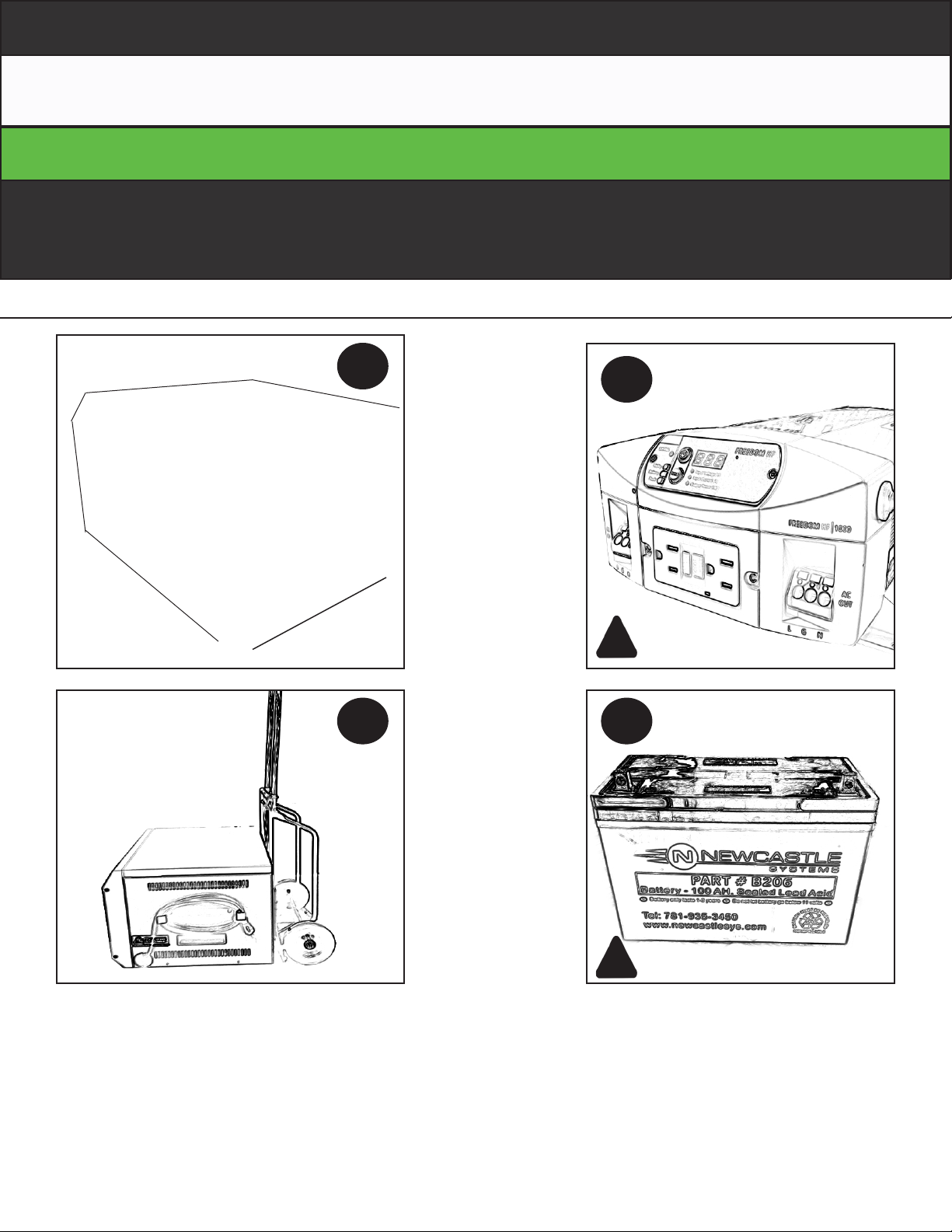
1. Fully ventilated Steel Cabinet
2. 100 watts 960 model Inverter / Charger
3. Optional Wheel-Base Tote
4. Battery
1
3 4
2
Unit Components

6
1. 960 Volt Meter
2. 9-3000 Volt Meter
3. Power Cord
4. Cord Reel
5. Removable Front Cover
6. Access to reset Inverter (GFCI)
7. Removable Top Cover
8. Handle
9. Screw 10/32-10 Hex Nut
10. Power Strip
11. Box Ventilation
12. Back
13. Knock-out
2
1
5
7
4
8
9
12
11
13
3
9
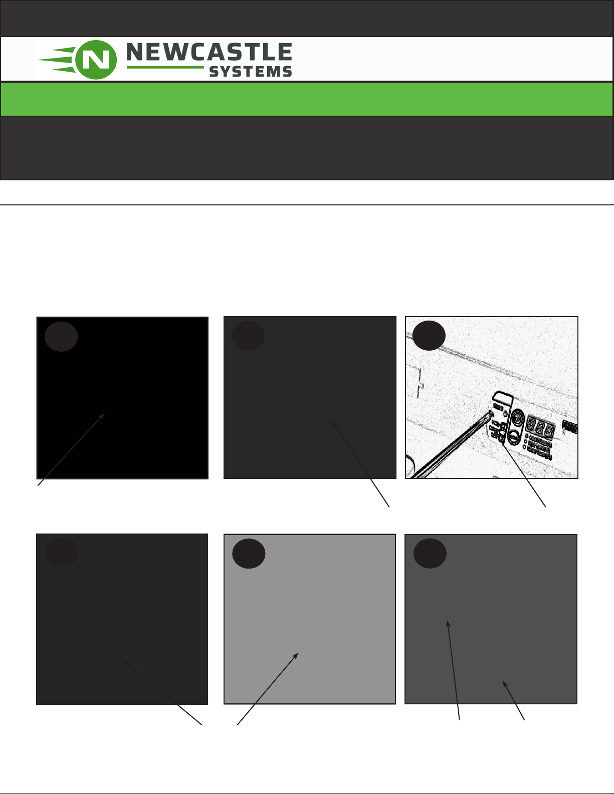
Feature Identication
6

7
2
1
3
1. Detach the Front cover using the 10/32 HEX-KEY nut wrench to remove the front cover
2. Press and hold the Green ON bottom for ten second to start the unit
3. Make sure the switch is ON in the power strip attached to the unit
4. Connect your equipment according to the inverter power capacity
4
Operation
8
Assembly Instructions
Voltage Meter Installation
456
1. Connect in the appropriate order the wires from the battery to voltage meter
2. Attach and secure Bracket to the (9-3000) Voltage Meter
3. Attaching the Inverter Voltage Meter to the Battery Box
4. Connect the communication cable to the back of the voltage meter
5. Attaching to the battery box the safety bracket for the Inverter (960) voltage meter
6. Voltage Meters Display
From Battery Terminals
(+) Red to number 1
(-) Black to number 2
(+) Green to number 4
Attaching the 9-3000 volt meter safety bracket Attaching the 960 Volt meter
Connecting the communication cable to the 960 VT Attaching the 960 volt meter safety bracket
960 and 9-3000
Volt Meters Display
12 3
9
(-)
(+)
43
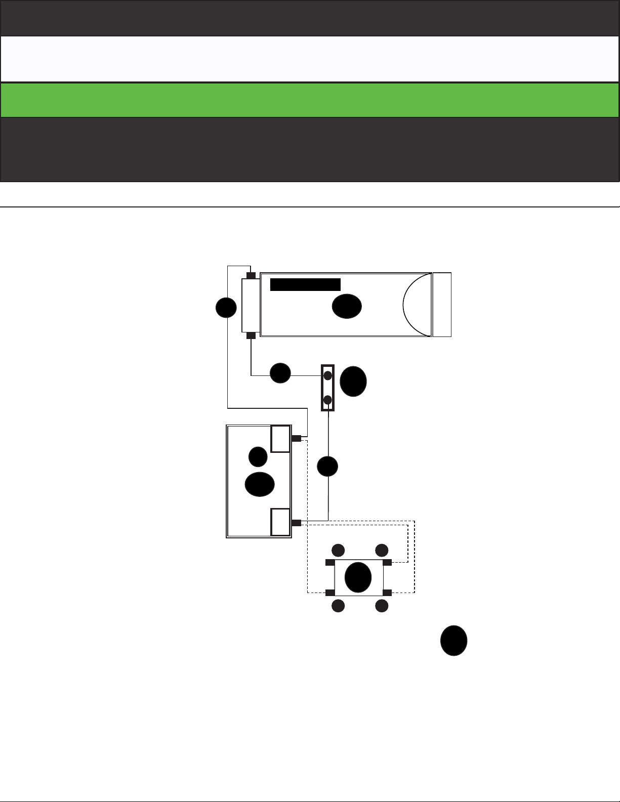
A
(-)
(+)
C
B
D
• A-Inverter
• B-FuseBlock
• C-Battery1
• D-VoltMeter
Battery
2 1
9-3000VoltMeter
FuseBlock
960Inverter
9-3000 Volt Meter Set-up
1. RedwireonMeter (1)toBattery(+)terminal
2. BlackwireonMeter(2)toBattery(-)terminal
3. NoConnection
4. GreenwireonMeter(4)toBattery(+)terminal
ONE BATTERY SET-Up
One Batteries Set-up
1. InverterBlackwire(-)toBattery (-)
2. InverterRedwire(+) toFuseBlock Aterminal
3. FuseBlockBterminalRedWire(+)toBattery (+)
1
1
2
3
D
Battery Set-Up

10
(-)
(+)
43
A
(-)
(+)
C
B
D
• A-Inverter
• B-FuseBlock
• C-Battery1And2
• D-VoltMeter
Battery
2 1
9-3000VoltMeters
FuseBlock
960Inverter
9-3000 Volt Meter Set-up
1. RedwireonMeter (1)toBattery(+)terminal
2. BlackwireonMeter(2)toBattery(-)terminal
3. NoConnection
4. GreenwireonMeter(4)toBattery(+)terminal
TWO BATTERY SET-Up
Two Batteries Set-up
1. InverterBlackwire(-)toBattery (-)
2. InverterRedwire(+) toFuseBlock Aterminal
3. FuseBlockBterminalRedWire(+)toBattery (+)
4. FuseBlockBterminalExtensionwire (+)toBattery(+)
5. Blackwire(-)onBattery #1to(-)terminalonBattery#2
1
1
(-)
(+)
C
2
Battery
2
3
4
D
Two Batteries Set-Up

11
Tips To Extend Battery Life
-1 Charge the Battery before using the NB-PS, to insure the NB-PS is fully charge
-2 Monitor the battery status meter on the cart volt meter.
-3 Batteries should not be stored in discharged below 11.5 volts as this will shorten the life of the battery
-4Batteries should not be stored in a discharged state for more than 1 or 2 days. They should be charged as
soon as possible after each use (Otherwise it can void the warranty)
-5 Avoid exposing battery to heat, service life shortened at ambient temperature above 85 F
-6 Batteries always should be charged in a secured but ventilated enclosure
-7 When Powering equipment on the cart one can have the charger plugged-in if necessary. In case, the AC
Power will pass throe the charger and power your equipment directly.
-8 When not in use, the system charger can be plugged into the AC power to ensure the battery remains in
optimal state
-9b Charging system is trickle charger so leaving it plugged in will NOT damage the battery
-10 Make sure that the terminals on the battery are tight as are the screws holding the wires inside the
inverter/ charger.
34 South Hunt Rd., Amesbury, MA 01913 / USA
P. 781.935.3450 www.newcastlesys.com
This manual suits for next models
3
Table of contents
Other Newcastle Systems Power Pack manuals


