Newgy Industries Robo-Pong 2055 User manual

www.newgy.com
Robo-Pong 2055 and Robo-Pong 1055
OWNER'S MANUAL
•2055 Quick Start ......... 2
•1055 Quick Start ............. 4
•Operation .......................6
•Robot Positions ......... 18
•Misc. Adjustments ..... 19
•Drill Diagrams ..............21
•Speed Calib. Target . . 27
•RP.2.PC ......................... 28
•Important Notices .... 34
•Take-Down, 2055 ......35
•Maintenance ................37
•Chip Replacement ... 38
•Exploded Views ........ 39
•Parts List ...................... 44
•Warranty & Repair ... 46

2
2055 QUICK START
Pull down support legs
Place the robot on the table with the
open front side facing you. Pull the curved
black metal support legs toward you.
Spread Support Legs Apart
Spread out the sup port legs to their
fully open position.
Join Net Support Tubes
Turn the robot around 180° so the Net
Support Tubes are now facing you.
Grasp the second
tube from your
right and pull up,
removing it from its
storage hole. Place
the bottom of this
tube into the top
of the first tube
on your right as
shown. Repeat on
the left side.
Gently Lower Ball Trays
Grasp one of the Ball Return Trays,
lift straight up to unlock it, grasp the
adjacent Net Support Tube, and slowly
lower them into position. Be careful
not to let the tray or support tube slam
down. Repeat on the other side.
Verify All Parts
Unpack all the parts and check that all
are present. If unable to identify a part,
look for a small silver label with the part
name. If a part is missing, please contact
Newgy. You may want to keep your box
and styrofoam pieces in case you need to
ship your robot.
1
5
2
3
4
Pong Pal
(U.S. Only)

3
Attach the Robot to the Table
Pick up the robot by the center base
and secure it to the table by angling
it downward and against the table.
The support legs should be as wide as
possible before they go underneath the
table and the front support triangle sits
on top of the table.
Attach the Side Nets
Attach the side nets to your table tennis
table net by slipping the red flexible
band over your table net’s support
base and looping it over the table net’s
clamp screw.
Adjust Head Angle
Tilt the head downward as far as
possible by loosening the Brass Knob
and then re-tighten
after moving head.
Verify that the
word “topspin” is at
the top of the ball
discharge hole.
Place Balls* in Bucket
Open the bag(s) of balls. Wash and dry
them, and then place in the Ball Tray.
Add any additional new table tennis balls
that have been washed and dried, or any
used balls with a worn surface. All balls
must be 40mm or 40+mm in diameter.
(*Included with U.S. robots only.) Do not
mix 40mm and 40+mm balls.
6
8
9
10
11
7
Connect Cable to Robot
Plug one end of the Connec tor Cable into
the 5-Pin Connector on the back of the
robot as shown. Take
the other end of the
cable to the player's
end of the table.
Attach Bracket to Control Box
Turn Control Box upside down on the
table. Take the Mounting Bracket and
align the hole in the mount ing arm with
the threaded insert of the Control Box.
Secure bracket with Mounting Screw.
Leave Control Box
laying face down.
12
13
Connect Cables to Control Box
Bring the free end of the Connector
Cable to the pla yer’s end of the table.
Plug the Connector Cable into the 5-pin
socket on the bot tom of the Control
Box. Then insert
the Transformer’s
pin into the power
jack of the Control
Box.
Adjust Bracket to Top
Thickness
Pick up the Control Box and looking
across the round rubber pad of the
Adjustment Screw, raise or lower the
height of the rubber pad so it aligns
with the nearest mark on the bracket's
label that corresponds with the
thickness of your table's top.
Attach Control Box To Table
Angle the opening be tween the two
rub ber pads of the Mount ing Brac k et
towards the bot tom of your table's
apron. Slip the bracket onto the table.
The rectangular rubber pad of the
bracket should sit flat on the table's
top surface. If it is not flat, loosen or
tighten the Adjustment Screw until the
pad lays flat. This
is not a clamping
mechanism—do
not overtighten!
14

4
1055 QUICK START
15 17
Position Your Control Box
Place the Control Box on the side of the
table about one foot from the end. If you're
right-handed, place it on the left side of the
table. If you're left-handed, place it on the
right side. Plug
the Transformer
into any suitable
electrical socket.
Get Ready To Play!
If not already on, turn the Control Box
on by pressing the Power button.
Adjust the Ball Speed to 8 by pressing
the + button. Pick up your paddle and
press the Stop/Start button. The balls
will start loading into the robot. It
takes about 15 seconds before the
first ball is shot out. It will be
delivered down the centerline of the
table with Topspin.
16 To Connect Control Box to PC
(Optional)
If you want to connect your robot to
a PC, connect any USB-A to USB-B
Printer cable (not included) to both the
control box and your Windows® PC.
Detach Robot Body
Loosen the two Wing Nuts holding
your robot body onto the Ball Bucket.
Ro tate the black,
rectangular Clip
Washers 180˚. Pull
the Robot Body
off the bucket.
Verify All Parts
Unpack all the parts and check that all are
present. If unable to identify a part, look for a
small silver label with the part name. If a part is
missing, please contact Newgy. You may want to
keep your box and styrofoam pieces in case you
need to ship your robot.
1 2
Warranty &
Tell-A-Friend
Flyer
Quick Start
Guide
Pong Pal
(U.S. Only)
Attach Bucket Extender
Slide the Bucket Ex ten der onto the top
of the bucket so that the hooks on the
bottom of the Extender capture the
top lip of the Bucket. Stop when the
hook on the front of the Extender grabs
the front lip of the Bucket. It may be
nec es sary to lift the bottom rear of the Ex-
ten der over the Locating Tab protruding
above the rear lip of the Bucket. Reattach
the Robot Body to the Bucket by reversing
step 2.
3

5
Place Balls* In Bucket
Open the bag(s) of balls. Wash and dry
them, and then place in the Ball Bucket.
Add any additional new table tennis balls
that have been washed and dried, or any
used balls with a worn surface. All balls
must be 40mm or 40+mm in diameter.
(*Included with U.S. robots only.) Do not
mix 40mm and 40+mm balls.
Adjust Head Angle
Tilt the head downward as far as possible
by loosening the Brass Knob and then
re-tighten after moving head. Verify
that the word “topspin” is at the top of
the ball discharge hole.
5
4
Position Robot On Table
Position the robot
in the center of the
table close to the
end line as shown.
The robot’s head
should be in line
with the centerline
of the table.
Connect Cables To Control Box
Bring the free end of the Connector
Cable to the pla yer’s end of the table.
Plug the Connector Cable into the
5-pin socket on
the bot tom of
the Control Box.
Then insert the
Transformer’s
pin into the
power jack of
the Control Box.
Attach Bracket To Control Box
Turn Control Box upside down on the
table. Take the Mounting Bracket and
align the hole in the mount ing arm with
the threaded insert of the Control Box.
Secure bracket with
Mounting Screw.
Leave Control Box
laying face down.
Connect Cable To Robot
Plug one end of the Connec tor Cable into
the 5-Pin Connector
on the back of the
robot as shown. Take
the other end of the
cable to the player’s
end of the table.
6
8
9
10
7
Adjust Bracket to Top Thickness
Pick up the Control Box and looking
across the round rubber pad of the
Adjustment Screw, raise or lower the
height of the rubber pad so it aligns
with the nearest mark on the bracket's
label that corresponds with the
thickness of your table's top.
11 Attach Control Box To Table
Angle the opening be tween the two
rub ber pads of the Mount ing Brac k et
towards the bot tom of your table’s
apron. Slip the bracket onto the table.
The rectangular rubber pad of the
bracket should sit flat on the table’s
top surface. If it is not flat, loosen or
tighten the Adjustment Screw until the
pad lays flat. This is not a clamping
mechanism—do not overtighten!
12 Position Your Control Box
Place the Control Box on the side of
the table about one foot from the end.
If you’re right-handed, place it on the
left side of the table. If you’re left-
handed, place it on
the right side. Plug
the Transformer into
any suitable electrical
socket.

6
CONTROL BOX FEATURES (ALL MODELS)
All robot functions are controlled electronically by the
Control Box. It uses a powerful programmable micropro-
cessor to run motors, monitor sensors, execute programs,
and display information on an easy to read LCD. You con-
trol it with 8 color coded buttons to navigate through the
menus and adjust values of each function. Figures 1A and
1B point out the button, connections, and features of the
digital Control Box.
1. LCD—Displays the menus, messages, and settings
for your robot in one of 6 different languages.
2. Power (
|
/) Button—Colored orange, this button
turns your Control Box on or off.
3. Test (✓)Button—Colored yellow, this button has
various functions depending upon the currently selected
mode. These functions are detailed under the Mode sec-
tions starting on page 7.
4. Stop/Start (■/▶)Button—Colored red and green,
this button starts and stops ball delivery. After pressing
this button, there will be a 3 second start up beeping
sequence to allow time to ready yourself for the first shot.
5 & 6. Minus (–) & Plus (+)Buttons—Colored gray
and shaped like arrows pointing left and right, press to
increase or decrease values or otherwise allow selection of
the parameters available for the selected function.
7 & 8. Up (⬆)& Down (⬇)Buttons—Colored gray and
shaped like arrows pointing up and down, press these but-
tons to navigate up and down through the menus.
9. OK/MENU Button—Colored white and square-
shaped, press this button to go to the Main Menu and
select the Mode.
10. Power Jack—Plug the transformer in here to con-
nect the robot to an electrical source.
11. 5-Pin Connector—Plug the gray Connector Cable
in here to connect the Control Box to the main robot body.
12. Female USB Connector—Plug the USB cable (user
supplied) in here to connect the robot to a PC.
13. Male DB-9 Connector—Plug the Linking Cable
from the Pong-Master Scoreboard in here. Pong-Master is
an optional accessory.
14. Mounting Screw Insert—Screw the black-knobbed
Mounting Screw in here to secure the Control Box to the
Control Box Mounting Bracket.
OPERATION OF YOUR ROBOT
CONTROL BOX
TOP VIEW
FIGURE 1A
1
2
3
4
56
7
8
9
10
11
12
13
14
CONTROL BOX
BOTTOM VIEW
FIGURE 1B
13 14
To Connect Control Box to PC
(Optional)
If you want to connect your robot to
a PC, connect any USB-A to USB-B
Printer cable (not included) to both the
control box and your Windows® PC.
Get Ready To Play!
If not already on, turn the Control Box
on by pressing the Power button.
Adjust the Ball Speed to 8 by pressing
the + button. Pick up your paddle and
press the Stop/Start button. The balls
will start loading into the robot. It takes
about 15 seconds before the first ball is
shot out. It will be delivered down the
centerline of the table with Topspin.

7
BALL SPEED 00
L POSITION 10
R POSITION 10
WAIT 01.00s
BALL SPEED sets how fast the Ball Speed Motor spins.
This determines both how fast the ball is discharged and how
much spin is placed on the ball. The higher this setting the
more speed and spin. Setting of 0 means the motor is off and
will result in balls falling out of the discharge hole. Maximum
setting is 30. (Tip: for top ball speed, clean the Discharge Wheel
and Friction Block before using.See page 37.)
BALL SPEED 00
L POSITION 10
R POSITION 10
WAIT 01.00s
L POSITION sets the leftmost position to which a ball is
delivered. A setting of 0 correlates with an extreme angle off
the left sideline; 5–6 with the middle of the left court; 10 with
the centerline of the table; 14–15 with the middle of the right
court; and 20 with an extreme angle off the right sideline.
Figure 2 below illustrates all of the 21 possible positions (0–20).
20
0
10
812
614
416
218
9
711
513
315
117 19
OSCILLATOR POSITIONS
FIGURE 2
CONTROL BOX MENU SYSTEM (ALL MODELS)
All functions of the Control Box are accessible through its
menu system. The menu system is displayed on its LCD
screen. Since the screen is limited to showing a maximum
of 4 lines of 16 characters, most menus will have more than
1 page. Additional pages of a menu are indicated by a
downward arrow on the bottom line of the display or an
upward arrow on the top line. This menu system functions
very much like the menu system on many cell phones.
To navigate the menu system, simply press the Down
Button to select the next line. As lines are selected they
reverse colors with a black background and white charac-
ters. When deselected, a line will have black characters on
a white background. If you navigate to a bottom line that
contains a downward arrow (as shown at the end of the
WAIT line of the L POSITION illustration to the right),
pressing the Down Button will reveal the next page with
up to 4 new functions.
You may also go upward through a menu by pressing
the Up Button. And if you arrive at a top line with an
upward arrow (as shown in the COUNT illustration on the
next page), pressing the Up Button will reveal a new page of
functions.
Once you have selected a function, you change the val-
ues for that function by using the – and + Buttons. If the
values are numerical, the – Button will decrease the value
while the + Button increases the value. A single quick but-
ton press will change the value by one increment. Holding
the button down will accelerate the rate at which the val-
ues change until you release the button.
MAIN MENU (ALL MODELS)
The Main Menu serves as the access control to the 4 oper-
ating modes. It can be accessed by pressing the OK/Menu
Button. When that button is pressed, the Main Menu is dis-
played. The Main Menu consists of a single page. This
menu has 4 selections: (1) NORMAL, (2) DRILL, (3) PC,
and (4) SETUP. To enter one of these modes, select one and
then press the OK/Menu Button.
NORMAL
DRILL
PC
SETUP
Tip: Press OK/Menu once in any mode to instantly return
to the Main Menu. The robot will cease any action it's currently
performing and wait for your next instruction. This is especially
helpful if you get "lost" in the menu system.
NORMAL MODE (ALL MODELS)
NORMAL Mode is used when the player wants to set
each function manually. This is most like how other robots
typically function. Normal Mode is also the default mode
when the Control Box is first plugged into power. This
mode has 3 pages of functions.
Tip:If ever you want to return to Normal Mode, press the
OK/Menu Button twice from any menu to go to Normal Mode.

8
A position setting is really a line of direction coming
from the robot. Selecting a position number results in a ball
being thrown somewhere along the dotted line that corre-
sponds with the number. The Head Angle, Ball Speed, and
Spin determine where a ball is delivered along that line.
If the robot is not positioned at the center of the endline,
these trajectories will change accordingly. See Positioning
Your robot & Controls on page 18 for more info.
When L POSITION is set, it automatically sets R
POSITION. If both positions are the same, the ball will
be thrown to only one position. If L POSITION and R
POSITION are different, then balls are alternately thrown
first to one position and then to the other position.
BALL SPEED 00
L POSITION 10
R POSITION 10
WAIT 01.00s
R POSITION sets the rightmost position to which a
ball is delivered. This setting can be changed without affect-
ing the L POSITION. However, if L POSITION is changed,
R POSITION will need to be reset. Remember, when L & R
settings are the same, balls are delivered to only one posi-
tion. When they are different, balls are delivered alternately
between the two positions.
BALL SPEED 00
L POSITION 10
R POSITION 10
WAIT 01.00s
WAIT is the amount of time (interval) between one shot
and the next shot in seconds. An easy way to remember this
setting is to think, "How long do I want to wait before the
next shot?" If the pace seems too slow and you want to wait
less, decrease WAIT and ball delivery becomes more rapid.
If the pace is too fast and you want to wait more, increase
WAIT and ball delivery will slow down.
WAIT can be changed in 0.05 second increments from
0.35 to 50 seconds. However, the minimum setting is dyna-
mically linked to L POSITION and R POSITION settings.
The larger the difference between L and R, the longer the
robot must wait before delivering the next ball. This is
because it takes a minimum amount of time for the robot to
change positions. For every difference of 2 in the settings
between L & R, another 0.05 is added to WAIT.
For example, if L & R are both set to 5 (no oscillation), the
minimum WAIT is 0.35 seconds. But if L is set to 0 and R to 20
(a difference of 20), 0.50 is added to the minimum WAIT to
allow time for the robot's head to sweep from the far left side-
line to the far right sideline. In this example, the minimum
WAIT would change from 0.35 to 0.85 seconds with a differ-
ence of 20 in L & R positions. This ensures that a ball is not
shot out until the robot has swept to the correct position.
Please be aware that WAIT is not absolute. This setting
may vary a little due to a number of factors, but in general,
it is accurate to within ±10%. WAIT also is involved in the
calculations for TIME (explained after COUNT).
COUNT 0000
TIME 0:00:00
OSC RANDOM OFF
SPEED RANDOM 00
COUNT indicates the number of balls that the robot
delivers before it stops automatically. If COUNT is set to 0,
COUNT is ignored and the robot will keep throwing balls
until the Stop/Start Button is pressed.
If COUNT is more than 0, it will decrement by 1 every
time a ball is thrown until it reaches 0. If Stop/Start Button is
pressed before COUNT reaches 0, delivery will stop.
Pressing the Stop/Start button a second time will resume the
COUNT where it was when it was stopped. Once COUNT
reaches 0, it must be reset to a new number before it
becomes active.
COUNT is synced with TIME (discussed next). As
COUNT is changed, TIME dynamically changes to reflect a
multiplication of COUNT times WAIT. For example, with
WAIT set to 1 second and COUNT to 61, TIME would show
0:01:01 (1 minute, 1 second).
COUNT 0000
TIME 0:00:00
OSC RANDOM OFF
SPEED RANDOM 00
TIME shows how long the robot will continue throw-
ing balls until it stops automatically. TIME is displayed in
HR:MIN:SEC format. A display of 1:01:01 indicates 1 hour, 1
minute, and 1 second.
TIME is restricted to increments of WAIT rounded to
the next second. For example, if WAIT is 1.50 seconds and
TIME is set to 0:00:03, COUNT would show 2. If TIME is set
to 0:01:30, COUNT would show 60. However, TIME cannot
be set to something like 0:00:05 because that time is not an
even increment of WAIT.
TIME is similar to COUNT—a setting of 0 deactivates
this function and more than 0 causes the robot to keep run-
ning until the value becomes 0. Interrupting TIME by press-
ing the Stop/Start Button simply pauses the countdown
until the Stop/Start Button is pressed a second time.
Having TIME and COUNT dynamically linked together
makes it easy to regulate your training routine by number of
balls thrown or by overall time. If you're used to doing a par-
ticular routine for 100 balls, set COUNT to 100 and the robot
automatically calculates the time it takes to throw 100 balls. If
you prefer to regulate your workouts by time, set TIME to
0:03:00, for example, to do your routine for 3 minutes before
the robot stops automatically. If you don't want to use TIME
or COUNT to stop ball delivery, set them to 0 and you can
control ball delivery manually by pressing the Stop/Start but-
ton.
TIP: Since TIME and COUNT can be set to very high num-
bers, there is a trick to greatly speed up the rate at which the
value changes. Press and hold the – or + Button and then press
the OK/Menu Button. Values will change much more rapidly.

9
COUNT 0000
TIME 0:00:00
OSC RANDOM OFF
SPEED RANDOM 00
OSC RANDOM turns the oscillator randomization fea-
ture on and off. It requires L POSITION and R POSITION
to be set to different numbers for it to have any effect.
When off, balls are thrown alternately to the left and right
positions. When on, balls are thrown randomly between the
left and right positions.
For example, if L POSITION is 5, R POSITION is 10, and
OSC RANDOM is OFF, balls are delivered alternately to posi-
tions 5 and 10. However, if OSC RANDOM is changed to ON,
then balls will be placed anywhere between positions 5 and
10; i.e., positions 5, 6, 7, 8, 9, or 10. The robot will pick one of
these numbers and throw a ball to the position it chooses.
COUNT 0000
TIME 0:00:00
OSC RANDOM OFF
SPEED RANDOM 00
SPEED RANDOM varies the BALL SPEED so balls are
thrown to different depths on the table. The value entered
is added to the value for BALL SPEED to give a range of
numbers from which the robot can randomly pick.
For example, BALL SPEED is set to 12 and SPEED
RANDOM is set to 6. This gives a range of ball speeds from
12 (very short, close to the net) to 18 (very deep, close to the
endline). The robot will randomly pick a number from
within this range—12, 13, 14, 15, 16, 17, or 18—and throw a
ball at that speed.
A value of 00 means no randomization. Maximum val-
ue is 10. Be cautious about using too high of a value as it
could cause balls to be thrown off the end of the table.
Tip: Set the BALL SPEED to the slowest desired speed first,
say 15. Then, without changing the head angle, experiment to see
what BALL SPEED setting will throw a ball just past the end of
the table, say 19. Subtract 1 from this larger number to find the
maximum speed that still lands the ball on the table—in this case,
18. Subtract the slowest ball speed, 15, from this maximum speed,
18, to give the maximum SPEED RANDOM setting—3.
WAIT RANDOM0.00
WAIT RANDOM causes the WAIT setting to vary by a
certain amount of time. The entered value is added to the
WAIT time to provide a range of time for the interval
between two consecutive shots. Like WAIT, this setting can
be changed in increments of 0.05 seconds. Maximum WAIT
RANDOM is 1.00 seconds. A setting of 0.00 means no ran-
domization is added to the wait time.
For example, WAIT is 1.00 seconds and WAIT RANDOM
is 0.20. These settings would provide a range of wait times
between 1.00 and 1.20 seconds. The robot could pick any time
among the following—1.00, 1.05, 1.10, 1.15, or 1.20 seconds.
Using WAIT RANDOM makes it difficult to develop a
rhythm and predict when the next ball will be delivered.
This encourages the user to maintain a good ready position
between each shot and only move after the ball is shot out
from the robot.
Also be aware that the greater the WAIT RANDOM is,
the less and less accurate TIME and COUNT become. This
is because the amount of time between each ball can no lon-
ger be accurately calculated since the interval between each
shot is constantly changing.
You can use 1, 2, or all 3 randomization controls at once.
Combining them together can make for very unpredictable
ball deliveries. It is recommended that you use controlled
randomization. Add randomness in small increments only
after consistency is attained without randomization. As
technique improves, gradually increase the amount of ran-
domization to more closely simulate live play.
In Normal Mode, the yellow Test Button is used to give
1 or more balls to test your settings. Press Test once and 1
will appear on screen. After a brief delay, 1 ball will be
thrown using the current BALL SPEED and last position
settings. If you hold the Test Button down, the number
shown on screen will keep advancing in increments of 1
until you release the button. Then, that number of balls will
be thrown. Please be aware that test balls thrown will not
reflect any random settings chosen (random position, speed,
or wait).
DRILL MODE (ALL MODELS)
NORMAL
DRILL
PC
SETUP
DRILL Mode allows access to the 64 drills that come
pre-programmed with your robot. Select Drill Mode by
going to the Main Menu, selecting DRILL and pressing OK.
There are 2 pages of functions in Drill Mode.
The 64 drills have been carefully selected to offer a variety
of drills for all playing levels, and to demonstrate how drills
can be created for training footwork, forehand-backhand tran-
sitions, serve return, and attack of high balls or backspin balls.
Each drill is diagrammed in the drill diagraMs section
starting on page 21. It is recommended that you keep these
diagrams next to your table tennis table when using Drill
Mode to quickly refer to the diagrams and select a drill for
training a particular aspect of your game. These diagrams
also provide information on what type of shots the player is
expected to use during the drill and what spin and head
angle settings to use. Create your own drill diagrams by
downloading a blank drills diagram page from the Down-
loads page of www.newgy.com, printing it off and using
hand notations on those printed diagrams.
TIP: You can often create "new" drills by simply changing the
HAND setting. So, for instance, if you are right handed and have RIGHT
selected, Drill 52 will give two backhands and one forehand. By changing
RIGHT to LEFT, this same drill will give you 2 forehands and 1 backhand.

10
DRILL# 01
SPIN TOP
HEAD ANGLE 02.0
WAIT ADJUS 000%
The first 3 lines of each drill are reserved for settings
that are predefined for each drill. Except for selecting
another drill, these values cannot be changed. Press the +
Button to select a drill with a higher ID number and the –
Button for a lower numbered drill.
Once a drill is selected, you need to verify that the Spin
(see page 16) and Head Angle (see page 15) are correctly set
before starting a drill. Failure to do so will normally cause
the drill to not run correctly and landing spots will be dif-
ferent than the way the drill was designed.
Regarding Head Angle, the angle indication mecha-
nism is not precise. Therefore, it is recommended that if
balls within a drill are not landing in the correct spot, that
you first try slightly nudging the head angle either up or
down to see if this corrects the problem. For instance, if a
drill starts with a short serve, and the serve often hits the
net, raise or lower the head angle slightly so that the serve
still lands short, but it clears the net without touching it.
DRILL# 01
SPIN TOP
HEAD ANGLE 02.0
WAIT ADJUS 000%
WAIT ADJUS is used to increase or decrease the wait
time between each shot. The value can be changed from
-100% to +900% in 10% increments. Since WAIT is adjusted
by percentage, even drills that have different WAITS pro-
grammed within the drill will still run correctly. Players of
many different levels can use the same drill without need-
ing to rewrite the drill.
For example, let's say a drill has a WAIT of 1 second
between the 1st and 2nd ball and a WAIT of 0.80 seconds
between the 2nd and 3rd ball. If WAIT ADJUS is set to +010%,
the 1st WAIT would be changed to 1.1 seconds and the sec-
ond WAIT to 0.88 seconds. The drill would run slower so
the player has more time between each ball.
On the other hand, if WAIT ADJUS is set to -010%, the
1st WAIT is reduced to 0.90 seconds and the 2nd one to 0.72
seconds. This causes the drill to run at a faster pace, reduc-
ing the time the player has between every ball.
Except for the 5 Beginner level drills, the drills that
come with your Robo-Pong are written to simulate real-time
rallies. This means that wait times were selected to closely
approximate the actual wait times in a rally between two
players. If you are unable to keep up with the pace, add a
positive WAIT ADJUS until you can maintain the pace for
several minutes. Your goal should be to gradually and sys-
tematically decrease the WAIT ADJUS to 0.
And once you can keep pace with a drill in real time,
then strive to practice the drill at faster than real time by
decreasing WAIT ADJUS to a negative value. By using this
principle of progressive overloading, you can train your
movements to flow smoothly at faster and faster speeds.
You will react faster to the ball in actual game rallies and
you may start dominating rallies simply because you are
quicker than your opponent.
SPEED ADJUST 0
# OF REPS 0000
TIME 0:00:00
SPEED ADJUST increases or decreases the BALL SPEEDS
that are preset in a drill. The values range from -9 to +9. The
value is added to the BALL SPEED for each ball in a drill.
For instance, a drill has 2 balls in it, one with a BALL
SPEED of 14 and the other, 16. If SPEED ADJUST is set to
+2, the speed of the 1st ball changes to 16 and the 2nd ball
to 18. If set to -2, 1st ball changes to 12 and the second to 14.
SPEED ADJUST should be used sparingly, especially
on drills that have both short balls and long balls. Adjusting
the speed upward on such a drill would likely make the
short ball land too deep and the deep ball get thrown off
the table. Adjusting the speed downward would likely
make the short balls fall into the net and the deep balls land
in the middle of the table.
SPEED ADJUST is best used for drills having a single
BALL SPEED. These drills have all balls landing at the
same depth on the table. Check Preview (see beginning of
page 10) to see if all balls in a drill are thrown at the same
depth. Decrease SPEED ADJUST to make balls land shorter
on the table and increase it to get deeper balls.
SPEED ADJUST is also handy when used in conjunc-
tion with Head Angle. If the specified Head Angle results in
a ball that has a higher trajectory than you prefer, simply
lower the Head Angle and use a positive SPEED ADJUST
to have the ball land at the desired depth on the table.
Again, this works best on drills that have a consistent BALL
SPEED set for the entire drill.
SPEED ADJUST 0
# OF REPS 0000
TIME 0:00:00
# OF REPS is similar to COUNT of Normal Mode. It
automatically stops ball delivery after the specified number
of drill repetitions are completed. For instance, if set to 5,
and there are 3 balls in the drill, the robot would run the
drill 5 times (15 balls total) before stopping. Also a setting
of 0 deactivates this function and drills can only be stopped
by manually pressing the Stop/Start Button.
If a drill is paused (by pressing the Stop/Start Button),
before # OF REPS equals 0, the drill will resume at the start
of the repetition at which it was paused when the STOP/
START button is pressed again. For example, # OF REPS is
set to 5 and the drill is paused in the middle of the 3rd rep.
When resumed, the drill would repeat the 3rd repetition
since it did not completely finish when interrupted.

11
SPEED ADJUST 0
# OF REPS 0000
TIME 0:00:00
TIME stops a drill automatically after the specified
amount of time has elapsed. Like Normal Mode, where
TIME is dynamically linked to COUNT, in Drill Mode,
TIME is dynamically linked to # OF REPS. You can increase
or decrease TIME in increments of the estimated time it
takes to complete 1 full repetition of a drill.
For example, if it takes approximately 5 seconds to
complete 1 repetition of a drill, TIME would go up and
down in increments of 5 seconds. If a drill contains variable
WAIT times, this approximation will become less precise.
Also see TIME (for Normal Mode) on page 8 for further
explanation of this function.
PC MODE (ALL MODELS)
NORMAL
DRILL
PC
SETUP
PC Mode is used whenever you want to connect your
Robo-Pong to your Windows®PC to read drills from or
write them to the Control Box and to run drills directly
from the PC. This Mode consists of a single page:
PC MODE
MAKE CONNECTION
TO PC
RUN ROBO-SOFT
After seeing this screen, please verify that your PC is
connected properly via the USB port on the bottom on the
Control Box. This connection routine is discussed in more
detail on page 28. After making the connection, start up
your PC and then launch the RP.2.PC program that can be
be downloaded from Newgy.com.
After RP.2.PC is launched, it takes several seconds to
establish communications with the Control Box (be patient).
Once the launch routine completes, it confirms the connec-
tion by displaying a message at the top of the program's
main window.
Once the connection is confirmed, RP.2.PC can be used
to read from and write to the Control Box, and run drills
direct from your PC. If you switch out of PC Mode after
connecting, the check mark will disappear and you'll need
to reestablish communication once you return to PC Mode
by using the AutoConnect command. Please read the
RP.2.PC section (page 28) for more info.
Please be aware that a connection between your PC and
the Control Box does not need to be established if you only
want to open, work on, or save drills stored on your comput-
er's hard drive (or external drive connected to your comput-
er). A connection is only necessary whenever you desire to
communicate with the Control Box via RP.2.PC.
The yellow Test Button does not have any function
associated with PC Mode.
SETUP MODE (ALL MODELS)
NORMAL
DRILL
PC
SETUP
SETUP Mode provides access to a variety of calibration
routines, user interface settings, and personal preferences. It
consists of 2 pages. We recommend that you write these set-
tings down. When you update the firmware or restore fac-
tory defaults, these settings will be erased. Writing them
down will save time if you need to re-enter the values.
CONTRAST 15
HAND RIGHT
LANGUAGE EN
OSC CALIB 25
CONTRAST adjusts the contrast of the screen to im-
prove visibility under a variety of lighting conditions. The
range is from 00 to 30. Default setting is 15, which should
work best for most lighting conditions. However, if so
desired, the user can lighten or darken the screen by chang-
ing the value. Going down in value provides a lighter
screen; whereas, going up in value darkens the screen.
If this setting is changed to either extreme value, it may
appear that the screen is completely dark or that no infor-
mation is displayed. But by adjusting your viewing angle
and/or the amount of light hitting the screen, you may see
feint outlines of letters and/or numbers. Adjust the value
accordingly to make the screen more readable.
CONTRAST 15
HAND RIGHT
LANGUAGE EN
OSC CALIB 25
HAND is one of the unique features of the digital
Robo-Pong robots. It lets the user select their dominant
hand so that drills run correctly with regards to backhand/
forehand strokes. Values are Right (default) or Left. Select
the one that matches your dominant playing hand.
Since drills are normally written for right-handed play-
ers, who are the vast majority of players, this switch allows
a left-handed player to use drills written for a right-handed
player without needing to rewrite the drill. We recommend
that all drills be written for right-handed players so that
this switch works properly.
HAND only affects drills run from either DRILL Mode
or directly from your PC in PC Mode. It has no effect on
NORMAL Mode.
RP.2.PC
12
CONTRAST 15
HAND RIGHT
LANGUAGE EN
OSC CALIB 25
LANGUAGE allows selection of the desired language
for displaying the menu system and messages. Values are
EN (English), DE (German), FR (French), ES (Spanish), CN
(Chinese), or JP (Japanese). EN is the default. After selecting
the desired language, any press of another button will acti-
vate that language and all information displayed on the
LCD screen will be shown in that language.
If the menu system is displayed in a language that can-
not be read, another language can be chosen by using the
Language Selection Special Function (see page 13).
CONTRAST 15
HAND RIGHT
LANGUAGE EN
OSC CALIB 25
OSC CALIB is used to calibrate a position setting of 10
with the centerline of your table tennis table (see page 7 for
explanation of positions). Once position 10 is calibrated to the
centerline, all other positions will be properly calibrated as
well. Range of values is from 00 to 50. Default is set to 25.
Decreasing the value results in the ball's landing spot
shifting toward the left and increasing the value results in it
shifting to the right. To see if your oscillation needs calibrat-
ing, set the Spin to Topspin and the Head Angle to 8. Then
press the yellow Test Button once.
5 Balls will be shot out from the robot. Carefully
observe the landing spots of these 5 balls in relation to the
centerline. If the balls land in a cluster around the center-
line, no adjustment is necessary. However, if the 5 balls
cluster consistently to the right of the centerline, decrease
OSC CALIB until the 5 balls cluster around the centerline.
Similarly, increase OSC CALIB if the test balls consistently
land to the left of the centerline.
It is normal for balls to land slightly to the left or right
of the centerline, but of the 5 test balls thrown, there should
be roughly equal numbers that are thrown left or right of
the centerline. If balls are always thrown either on the cen-
terline or to the right, for example, go ahead and decrease
OSC CALIB to shift the cluster slightly to the left.
Before changing OSC CALIB, check to be sure the robot
is properly centered on the end of the table. The center sup-
port rib of the triangular shaped Front Support Plate (Key
#5 on page 44) should align with the centerline of the table.
SENSOR CALIB 10
ALARM CALIB 10
SPEED CALIB 10
255 255 255
SENSOR CALIB corrects poor ball feed performance.
Be cautious about changing this from the default value
until you have eliminated other causes, discussed below.
The Ball Sensor (#40, Figure H, page 45) detects when a
ball should be thrown out and is responsible for accurate
ball counting. If your robot begins to throw 2 balls at once,
doesn't throw out a ball when it is supposed to, or seems to
often hesitate immediately before a ball throw, you may
need to calibrate the Ball Sensor.
Values range from 00 to 20 with 10 being the default
value. Decreasing the value advances a ball's position in the
ball channel so the ball is sensed "earlier". Increasing the
value causes the ball to be sensed "later".
You would decrease the value if the robot doesn't throw a
ball out when it's supposed to or seems to often hesitate
immediately before ball throws. Increase the value if you often
get two balls thrown instead of 1 ball.
Before adjusting SENSOR CALIB, please eliminate other
more likely causes. It is normal for an occasional hesitation
before a ball throw, but this should not happen on regular
basis. This is caused by the pickup mechanism missing a ball
pickup and rapidly accelerating the feed wheel to "make up"
for the missed pickup. There will be a slight hesitation before
the ball feed mechanism can "catch up" after a missed pickup.
Also if the chip loosens from its chip holder, the Ball Sensor
will not work.
A common cause of missed ball pickups is that there are
not enough balls immediately in front of the ball pickup
mechanism. Add more balls to your robot to prevent this. If
several balls are not in contact with the Pickup Fingers (#46,
Figure I, page 43), they cannot be picked up. This mimics incor-
rect ball sensor calibration, but the true cause is simply there
are not enough balls for the pickup mechanism to work prop-
erly or something is preventing balls from rolling down into
the pickup mechanism.
Something else that can cause the ball sensor to not sense
balls correctly is that the steel lever attached to the sensor does
not protrude far enough into the ball channel. The lever needs
to protrude far enough into the channel that a ball cannot pass
by it without activating the sensor (you should hear a clicking
sound as the lever is depressed). If necessary, carefully bend
this lever inward so it detects balls properly.
Undersized balls may also cause this behavior. Please ver-
ify that all balls are 40mm in diameter (see page 17 for using a
Ball Dam2to check ball diameters). Robo-Pong 2055 and 1055
cannot utilize 38mm balls.
Lastly, something that causes double ball throws is a bro-
ken Ball Discharge Spring (#58, Fig. D, pg. 44). If this part is
broken, missing, or deformed, it is likely the culprit and
should be replaced before adjusting SENSOR CALIB. Forcing
the head angle to less than 1 can also cause this.
If you have eliminated other more likely causes, adjust
SENSOR CALIB by setting the head to Backspin and to Angle
7. Then press the yellow Test Button. The robot will begin
shooting balls into the table net and the balls will roll back into
the net system. If balls aren't being thrown into the table net,
adjust the Head Angle until they are.
Balls will be delivered to positions 12 and 16. Watch the
head carefully to be sure that one and only one ball is thrown
out each time the head completes its sideways travel. It likely
will take numerous balls to be thrown before a problem is
detected. Press any button to stop the test. If SENSOR CALIB
needs adjusting, select a new value and then repeat the test
until the problem disappears.

13
SENSOR CALIB 10
ALARM CALIB 10
SPEED CALIB 10
255 255 255
ALARM CALIB effects the sensitivity of the Ball Jam
Alarm. This alarm is activated whenever the resistance of
the Ball Feed Motor rises above a preset level. This causes
the alarm to sound and power to the Ball Feed Motor is cut
until the problem is resolved. This prevents damage to the
Ball Feed gears and other parts. For most users, this feature
will never be needed and should be kept at default value.
Dirty, broken, or oversized balls are the most likely
causes for this alarm to activate. Other causes are foreign
objects or anything else that would prevent balls from
being pushed smoothly through the ball channel.
The alarm has a range of adjustment to allow the user
to make it activate sooner or later than "normal". The range
is from 0 to 20 with 10 being the default value. If you desire
more sensitivity, you can increase the value. If you want
less sensitivity, decrease the value.
A likely scenario where you may consider decreasing
the sensitivity would be if the balls get very dirty and the
alarm starts activating. Instead of stopping and washing
the dirt off the balls, the user wants to continue playing
with dirty balls. Although not guaranteed, decreasing
ALARM CALIB may allow dirty balls to be used until such
time that they can be properly cleaned.
SENSOR CALIB 10
ALARM CALIB 10
SPEED CALIB 10
255 255 255
SPEED CALIB is used to fine tune the BALL SPEED.
For drills that have been created on a different Robo-Pong
to work correctly on your robot, it is important that BALL
SPEEDS on the two machines be calibrated so that a value
of, for instance 15, results in the same landing spot on both
robots. This problem would most likely be caused by com-
ponents wearing or aging.
Values range from 0 to 20 with 10 being default value.
Increasing the value results in more speed being added to
the ball; decreasing the value, in less speed. However, there
is an upper limit to this effect—no balls set at BALL SPEED
25 or higher will be affected by SPEED CALIB. So don't
think that increasing this value will result in faster top
speeds. BALL SPEED 30 is already set at the maximum for
the motor and the electronics controlling that motor. So set-
ting SPEED CALIB to 20 and using a BALL SPEED of 30
would not result in even more speed being applied to the
ball. As a matter of fact, it would cause the robot to run
worse, possibly resulting in an over-voltage situation where
power is cut off to the Control Box and causing it to reset.
SPEED CALIB should only be used as a last resort
when all other possible solutions do not resolve the prob-
lem. The first thing you should check if balls are not land-
ing where they should, is to check that the robot is level
and the Head Angle is set properly.
As discussed previously, the Head Angle Adjustment
Mechanism is not precise, so a Head Angle Setting should
be used as a general guideline, not as an absolute. In gener-
al, for any given head angle, the acceptable tolerance is
±0.25. So if the given Head Angle is 8, the acceptable range
for that setting is 7.75 to 8.25. Many times, speed "problems"
can be resolved simply by adjusting the head angle.
Another common cause of slower ball speeds is that the
rubber Discharge Wheel and/or Friction Block are dirty.
Dirt buildup on these two parts can cause a substantial
reduction in ball speeds. Clean these parts regularly to
maintain top speeds. See page 37 for recommended clean-
ing procedures.
To use SPEED CALIB, make a 6 x 6 inch paper target.
One is provided on page 27, but instead of cutting that tar-
get out, we recommend making a copy and using the copy.
Then follow the instructions as given on the target.
SPECIAL FUNCTIONS (ALL MODELS)
There are 4 special functions that can be accessed by press-
ing a combination of buttons on the Control Box: (1)
Language Selection, (2) Ball Unloading, (3) Self Diagnostics,
and (4) Factory Default Restoration. All special functions
begin by pressing and holding the OK/Menu Button until
the screen goes blank. Release the OK/Menu Button and
after a brief moment, the screen turns completely black.
Then press one of the gray arrow-shaped buttons as given
in the following descriptions:
Language Selection is particularly useful if the menu
system is displayed in a language that the user cannot read.
Press and hold the OK/Menu Button until the screen goes
blank and then release. Momentarily, the screen turns com-
pletely black. Now press and hold the Up Button. The fol-
lowing message appears in the currently selected language:
RELEASE BUTTON
WHEN YOU SEE
YOUR LANGUAGE
It will then begin cycling through all the languages,
one at a time, with a short pause before each one. When
you see the language you prefer, let go of the Up Button
and the menus will stay in that language. Press any button
to exit Special Functions mode and resume normal opera-
tions.
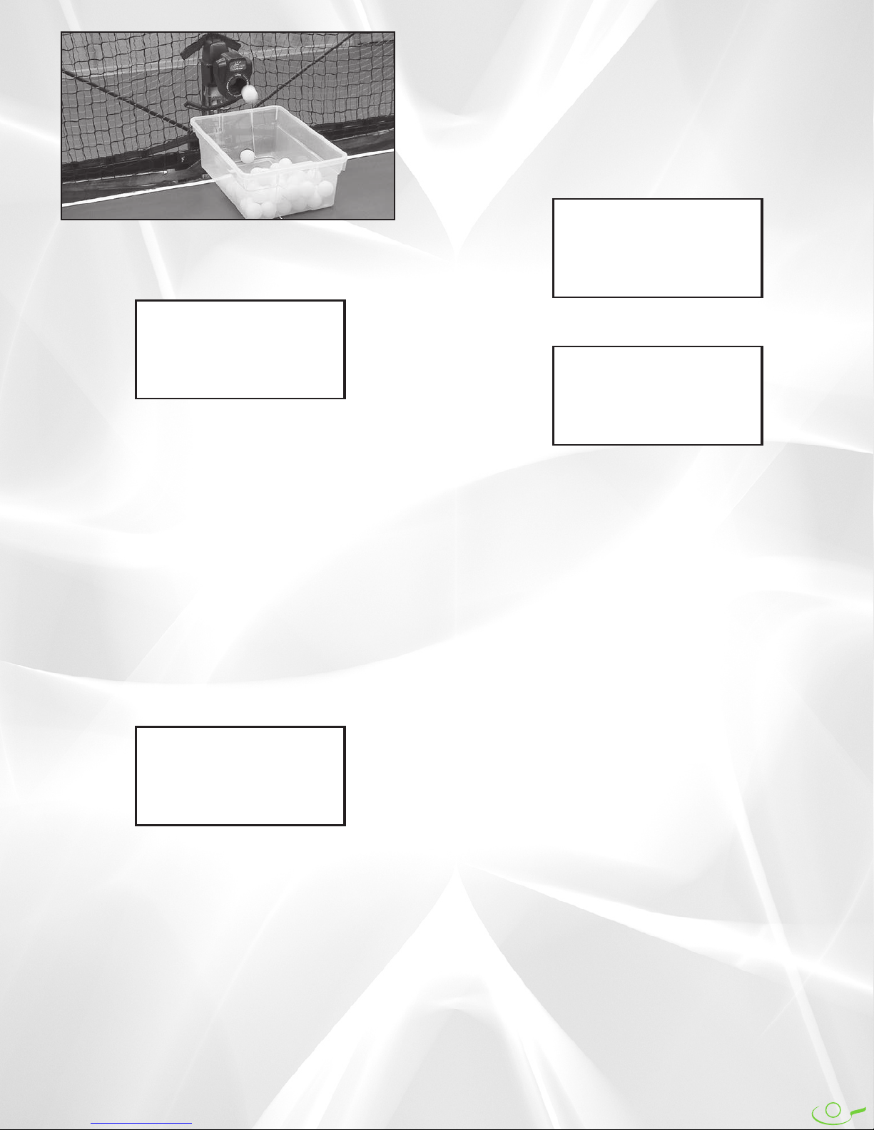
Ball Unloading is used when you want to quickly
empty balls out of the robot's trays2or bucket1. This is typi-
cally done when the user wants to practice serves by gath-
ering all balls from the robot and placing them into a bin.
Before using this function, get a medium-sized plastic
bin (available at many department & hardware stores). If
you have a Robo-Caddy, it's convenient if the plastic bin is
sized to fit into the caddy's tray.
14
overwritten during this procedure. As mentioned previous-
ly, it is handy to write down all values for functions in the
SETUP Mode, so you can quickly reenter them after you
use Factory Default Restoration. We have included a space
on the back cover to record your settings.
Like the other Special Functions, begin by holding
down the OK/Menu button until the screen goes blank and
then release that button. When the screen turns all black,
press the – Button. You will then see the following screen:
RESTORING
FACTORY
DEFAULTS
And after a moment, the screen will confirm that the
procedure completed successfully:
FACTORY
DEFAULTS
RESTORED
A few seconds later, the above screen disappears and
the system reboots and you are taken automatically to page
1 of the default Normal Mode.
Place the plastic bin under the robot's head. Then press
and hold the OK/Menu Button until the screen goes blank
and then release. After the screen turns completely black,
press the Down Button. The following message appears:
BALL UNLOADING
PLACE TRAY UNDER
ROBOT HEAD
In a moment, balls will start dropping out of the robot's
head at maximum frequency, landing in the plastic bin placed
underneath. In a short amount of time, all balls will be pulled
from the trays2or bucket1and deposited into the bin. Place the
bin on the top of the table or into the top of the Robo-Caddy
on the server's end of the table. Now practice your serves and
use the robot's net system to capture and collect your serves:
Self Diagnostics is used to help troubleshoot the robot
when having problems with the robot. This should be used
principally with a trained service technician who can prop-
erly interpret the codes provided. Always perform a
Factory Default Restoration (described next) before using
Self Diagnostics.
To activate, use the same routine described previously
for making the screen go black. Then press the + Button.
The screen will display the following message and then
generate a series of numbers in the last line:
TESTING SYSTEM
GIVE ERROR #S
TO TECHNICIAN
0123456789
Write down these numbers and give them to a service
technician. These codes may assist the technician with trou-
bleshooting the problem.
Factory Default Restoration is handy when you suspect
that a setting may be causing the robot to behave in a
strange manner. Restoring all settings to factory default
means that all values are set back to the default value for
each function This is a handy step to take when you suspect
that the robot is malfunctioning and should always be done
before calling for service help. It may clear up the problem
by itself.
Please remember to recalibrate your robot after using
Factory Default Restoration as any custom setting is

15
BALL TRAJECTORY (ALL MODELS)
The trajectory of a ball is regulated by adjusting the angle of
the robot head. The angle can be changed from low to high.
At its lowest setting (1), the ball will be delivered so it first
strikes the robot's side of the table, bounces over the net,
and lands on the player's side of the table (just like a serve).
At its highest setting (13), the ball will be delivered in a
high arc over the net (like a lob return).
The trajectory is adjusted by tilting the head up or
down. If the head will not tilt, loosen the Brass Knob on the
right side of the robot head. If the head does not stay at the
desired angle, tighten the Brass Knob slightly (see Figure 3).
For reference, there are head angle indicators next to
the Brass Knob numbered 1 to 13 (see Figure 4). These
indicators are not precise, so you may need to nudge the
head slightly up or down from a setting when a particular
head angle is provided.
WARNING: DO NOT adjust the head angle when the
head is moving side to side. Failure to follow these instructions
may result in broken parts and may void your warranty.
BALL SPEED directly influences the ball trajectory set-
ting. When the head is set so the ball first strikes the robot's
side of the table (robot “serving”—see Figures 5C & 5D),
maximum BALL SPEED is in the range of 10–15. As BALL
SPEED is increased, the head must be angled up to deliver
the ball so it first strikes the player's side of the table (robot
“returning”—see Figures 5A & 5B). As BALL SPEED is
increased even more, adjust the head angle down to pre-
vent the ball from being thrown off the end of the table.
INCORRECT ROBOT HEAD ANGLE,
ROBOT “RETURNING”
FIGURE 5A
HEAD ANGLE INDICATORS
FIGURE 4
CORRECT ROBOT HEAD ANGLE,
ROBOT “RETURNING”
FIGURE 5B
INCORRECT ROBOT HEAD ANGLE,
ROBOT SERVING
FIGURE 5C
CORRECT ROBOT HEAD ANGLE,
ROBOT SERVING
FIGURE 5D
Robot head is tilted too high, resulting
in ball being thrown off the end of the
table.
Same ball speed as Figure 5A, but
now robot head is tilted down so the
ball lands on the table.
When robot is set to serve onto its
side of table first, and the head angle
is too severe, the ball will rebound
abnormally high.
Same ball speed as Figure 5C, but
head angle has been raised slightly
so ball stays low to the net. With robot
serving, maximum ball speed is
limited to 10-15 before ball is thrown
off the end of table.
Robot Head
70
Angle Pointer
69
Brass Knob
Robot Head
Robot Head
Robot Head
If necessary, loosen
knob (69) to adjust
angle of head up or
down. Tighten knob
if head will not stay
in position.
ADJUSTING HEAD ANGLE
FIGURE 3
Head Angle Indicators

16
BALL SPIN (ALL MODELS)
Robo-Pong robots are capable of putting any type of spin
on the ball. Topspin, backspin, sidespin, and even combina-
tion spins can easily be selected. To change the spin, simply
rotate the head of the robot until the desired spin is at the
top of the Ball Discharge Hole (see Figure 6).
For combination spins, move the head until one of the
rotational arrows is at the top of the Ball Discharge Hole.
For instance, if the arrow between Topspin and R. Sidespin
is selected, the robot will deliver a ball containing both top-
spin and right sidespin. Likewise, if the arrow between
Backspin and L. Sidespin is selected, the robot will deliver
a combination backspin/left sidespin ball.
Before discussing how to return spins, it's important to
know that your robot simulates the play of a modern table
tennis professional using inverted sponge rubber. With
Robo-Pong robots, there is always some kind of spin on the
ball. To learn how to produce your own spin and return an
opponent’s (or the robot’s) spin, it is important to use the
correct equipment—a quality inverted or pips out sponge
rubber racket. Using old-style paddles such as hard rubber
or sandpaper will make it more difficult to control spin.
Each spin has a different effect on the ball and how the
ball reacts when you strike it with your paddle. Following
are some brief pointers to help you return the different
spins. More detail is available in the newgY robo-Pong
training Manual which is included with your robot if
bought in the U.S., or as a download from Newgy.com.
The secret to returning spin is to angle your paddle
correctly when contacting the ball. Any spin can easily be
returned if you angle your paddle properly. Set your pad-
dle angle at the beginning of your stroke and maintain the
same angle until your stroke ends. Avoid changing your
paddle angle during your stroke (see Figure 7).
Topspin causes the ball to dip downward as it travels
through the air. When you strike the ball with your paddle,
it has a tendency to pop up high in the air. To compensate
for topspin, angle your paddle face down as you stroke
through the ball in a forward and upward direction. Con-
tact the top surface of the ball (see Figure 7A).
Backspin causes the ball to rise upward and float as it
travels through the air. When you strike the ball with your
paddle, it has a tendency to go straight down into the table.
To compensate for backspin, angle your paddle face up-
ward as you push your paddle straight forward. Contact
the bottom surface of the ball (see Figure 7B).
Sidespin makes the ball curve sideways through the
air. Left sidespin makes the ball rebound off your paddle to
your right; right sidespin to the left. To compensate for left
sidespin, angle the paddle face to the left and contact the
right side of the ball. To compensate for right sidespin,
angle your paddle face to the right and contact the left sur-
face of the ball (see Figures 7C &7D).
Combination spins take on the characteristics of both
spins, although to a lesser degree than the pure spins. To
compensate for topspin/right sidespin, you must angle
your paddle face down and to the right and contact the top
left surface of the ball. Likewise, a backspin/left sidespin
ball is best returned by angling your paddle face up and to
the left and contacting the ball on its bottom right surface.
Spins are intensified by increasing the Ball Speed (see
page 7). You intensify both speed and spin every time you
turn up BALL SPEED. It is not possible to adjust Robo-
Pong robots to deliver a slow ball with lots of spin, for
instance. It is also impossible for Robo-Pong robots to
deliver a no-spin ball. Additionally, since backspin causes
the ball to rise, the maximum setting for BALL SPEED
when the robot is set on Backspin is approximately 15–17.
Rotate Head So
Desired Spin Is
Listed In Upright
Position
CAUTION:
Do Not Twist Power
Cord Around Head.
Rotate No More
Than 180° In Either
Direction From
Position Shown
FIGURE 6 PADDLE ANGLE ADJUSTMENTS
FOR VARIOUS SPINS
FIGURE 7
AB
CD
SPIN SELECTION

17
BALL DAMS (2055 ONLY)
Robo-Pong 2055 comes with a pair of Ball Dams. They serve
three functions: (1) they keep balls inside the Center Trough
when the robot is folded up, (2) they keep balls from enter-
ing the Center Trough when you want to remove the robot
body, and (3) they serve as a ball gauge for determining if a
ball is the proper size and whether it should be used in the
robot.
The Ball Dams, when used for functions 1 or 2, fit into
two retaining slots at the top of the Center Trough. When
not in use, the Ball Dams fit into their storage slots on the
side of the Center Trough (see Figure 8).
To use the Ball Dams when preparing the robot for stor-
age or transport, remove the Ball Dams from their storage
slots by pulling slightly up on the trays to reveal the stor-
age slots (see Figure 10). Then push all the balls into the
Center Trough and insert the Ball Dams into their retaining
slots (see Figure 9). To use the Ball Dams for function #2,
push the balls up into one of the Ball Return Trays and
quickly insert the Ball Dam into its retaining slot before the
balls can roll down into the Center Trough. The balls will be
out of the way and you can easily loosen the two wing nuts
and two clip washers, then pull up on the robot body to
remove it.
The hole in a Ball Dam serves as a handy ball checking
feature. The hole is exactly 40.6mm in diameter, which is the
largest allowable size for a table tennis ball. Robo-Pong 1055
and 2055 can use only 40mm or 40+mm balls. Do not use
38mm, 44mm, or any other ball size than 40mm or 40+mm.
Do not mix 40mm and 40+mm size balls. Use the hole to
test the roundness and size of balls used in the robot.
If you suspect a ball is out of round or too large, as indi-
cated by balls jamming within the robot, insert the suspect
ball into the ball checker hole. With your fingers, rotate it
around inside the hole to check all possible diameters of the
ball. The ball should have equal clearance through the hole
on all diameters. The ball should fit through the hole with-
out binding. It is also possible that a ball is too small. In this
case, you will notice a considerable gap between the ball
and the edge of the hole.
Note: Be aware that plastic balls (also called poly balls) are
identified with the marking 40+. They were introduced in 2014
and are approximately 0.5mm larger in diameter than the aver-
age celluloid ball (40mm), which is the material that has histori-
cally been used for table tennis balls. Plastic balls are marked
with 40+ instead of 40 that is used on celluloid balls. When
using the ball checker hole, there should be considerable more gap
when measuring celluloid balls than when measuring plastic
balls.
Ball Dam
Retainer Slot
Ball Dam
Storage Slot
Ball
Checker
Hole
15
Ball Dam
1
Center
Trough
BALL DAM & CENTER TROUGH
(2055 ONLY)
FIGURE 8
INSERTING BALL DAM
(2055 ONLY)
FIGURE 9
REMOVING BALL DAM
(2055 ONLY)
FIGURE 10
CHECKING BALL WITH BALL DAM
(2055 ONLY)
FIGURE 11
➥
➨
➨
Rotate Ball Inside
Hole To Check All
Diameters Of The
Ball. Ball Should
Pass Easily Through
Hole On All
Diameters.

18
POSITIONING YOUR ROBOT AND CONTROLS (ALL MODELS)
Robo-Pong robots are versatile in how they are positioned in
relation to the table. The 1055 normally sits on top of the table
as shown in robot positions 1–4 in Figure 12. They can also be
mounted in the optional Robo-Caddy and placed behind the
table like positions 5 & 6. The 2055 is typically mounted to
the end of the table at position 5, but can alternatively be
mounted in the Robo-Caddy just like the 1055.
Some positions offer certain advantages while other
positions compromise some of the robot’s functions. By
placing the robot in various positions you can achieve a
variety of angles and trajectories to simulate almost any
type of shot you would encounter in a regular game. The
following paragraphs explain this further.
Position 1—Robot positioned square to the table where
the centerline and endline of the table meet. This is the only
on the table position in which the 1055’s oscillator positions
will be accurate (see Figure 2, page 7). Also, this is the
desired starting position when first setting up the 1055.
Position 2—Robot positioned at the far left corner and
angled cross-court. This position will skew the 1055’s oscil-
lator positions toward the player’s right side of the table.
This position would be the preferred direction when simu-
lating typical right-handers’ forehand to forehand rallies.
Position 3—Robot positioned at the far right corner and
angled cross-court. Setting the robot in this position will
skew the 1055’s oscillator positions toward the player’s left
side of the table. Typical backhand to backhand play for
right-handers would be ideally simulated with the robot in
this position.
Position 4—A robot placed in this position has the
advantage of offering slower and faster ball speeds because
it is closer to the landing spot of the ball. At a Ball Speed
setting of 1, the ball is very slow and with light spin, but is
delivered deep on the player’s end. At a Ball Speed setting
of 30, the ball speed is very fast and simulates the angle
from which a typical kill shot would be hit. However, the
1055’s oscillator range is narrower than if the robot had
been positioned at the endline like Positions 1–3. This posi-
tion also is similar to the ball release point that most coach-
es use when doing multi-ball drills with a student.
Position 5—This is the normal position of the 2055
when it is attached to the end of the table, and its net system
would function normally. The 1055 would have to be
mounted in the Robo-Caddy to be in this position.
Positioned here, the 2055’s and 1055’s oscillator ranges
would be accurate.
Position 6—Mounted in a Robo-Caddy, both models
can be freely moved around in back of the table. The Robo-
Caddy also permits lowering or raising the height of the
robot. This is great for simulating deep shots such as chops,
lobs and loops. However, the oscillator ranges for the 1055
and 2055 are not accurate and the 2055’s net system is usu-
ally not effective at capturing balls when in this position.
Additionally, you need to purchase a Shielded Connector
Extension Cable to extend the length of the Connector
Cable from 11 to 22 feet. This permits the Control Box to
stay within reach of the player.
Robot
Pos. 1
Robot
Pos. 2
Robot
Pos. 3
Robot
Pos. 4
Robot
Pos. 5
Robot
Pos. 6
Right Hand
Player Left Hand
Player
Control Box
AB
These positions are only a few of the ones possible, but
they will give you a good idea of the pluses and minuses of
placing the robot in a particular position.
IMPORTANT NOTE: Even though the oscillator range
may not be accurate as described in Figure 2 on page 7 when the
robot is in certain positions, you should be able, with experimen-
tation, to find the correct settings to permit ball delivery over any
particular part of the table.
Figure 12 also illustrates the ideal positions for the Control
Box. If you’re right-handed, Position A is the preferred location
for the controls. If you’re left-handed, Position B is preferred.
Locating the controls in these suggested positions permits the
controls to stay within easy reach of the player’s free hand.
Since a player has a longer reach on the forehand side, it is
suggested that you position your body as shown. The over-
whelming majority of tournament level players use their back-
hand to cover about one-third of the table and their forehand to
cover the other two-thirds of the table.
ROBOT AND CONTROL BOX
POSITIONS
FIGURE 12

19
LEVELING ADJUSTMENT (2055 ONLY)
Robo-Pong 2055 is designed to sit level when attached to
the table. In proper position (Figure 13), the CT Support
Legs fit underneath the table and the CT Front Support
Plate sits on top of the table. If the robot does not sit level,
balls will not feed properly. If this condition occurs, it is
necessary to make some leveling adjustments. The first
adjustment is to level the table top by placing shims under
the table legs until the table top is level.
If this does not cause the robot to sit level, then it will be
necessary to make adjustments to the robot itself. The
Support Legs come with 3 sizes of Rubber Tips and 4 rubber
spacer-washers to accommodate different table top thick-
nesses, and cause the Center Trough to sit level. The Rubber
Tips are marked on their top with the table thickness they
are used with. The longest is used for 1/2″(13mm) tops. The
mid-size one is used on 3/4″(19mm) tops and comes pre-
installed. The shortest tip is used for 1″(25mm) tops.
In addition to these different sized tips, there are 4 rub-
ber spacer-washers which are used with the Rubber Tips
for finer adjustments. Either one or two of these spacer-
washers (depending on how much adjustment you need)
are placed inside the Rubber Tips before the tips are placed
on the end of the Support Legs.
Another reason why your robot may not sit level is that
it is not properly seated on the locating tab. When seated
correctly, the Support Flange of the Back Panel sits flush on
the Locating Tab that protrudes from the top of the Center
Trough or Ball Bucket (see Figure 14). Your robot serial num-
ber is located on top of this Support Flange.
TIP: If it is possible to adjust the level of the robot’s half of
the table independently from the player’s half, you may choose to
purposely give a slight slope to the robot’s half so balls that end
up on the table roll into the robot’s trays. If you make the table
unlevel, make sure the robot sits level by adjusting the Rubber
Tips as described above. In this case, it may be necessary to use
the Rubber Tip one size larger than normal and/or the rubber
spacer washers to level the robot.
ADJUSTING NET TENSION (2055 ONLY)
The Ball Return Trays should sit level at or just below the
level of your table top. If the tension of the Main Net is too
tight, the trays will be pulled up into a slight “V” shape
with the top edge of the trays above the level of the table
top. To correct this situation, loosen the adjustment straps
shown in Figure 15 until the trays sit level. If this adjust-
ment is insufficient, stretch the net by grabbing it with two
hands and pulling gently apart to relax the net fabric.
The Trap Net (the black net with large holes) slows
down your returns so more of them are captured. The size
of the holes is slightly smaller than the diameter of a ball.
Hard hit shots force the ball through the net and the ball
becomes trapped between the Trap Net and the Main Net.
When slowly hit balls contact the Trap Net, they do not
have enough force to go through the net, so they immedi-
ately drop down into the trays.
MISCELLANEOUS ADJUSTMENTS (2055 ONLY)
CENTER TROUGH ATTACHMENT
(2055 ONLY)
FIGURE 13
ADJUSTING MAIN NET TENSION
(2055 ONLY)
FIGURE 15
ADJUSTING TRAP NET TENSION
(2055 ONLY)
FIGURE 16
Table Tennis
Table
Back Of Robot
To Control
Box
Velcro
Straps
Robot
8,9
CT Support
Legs
92
Connector
Cable
Serial #
Located
Here
10, 11, 12
CT Support
Leg Rubber
Tip—Come
In 3 Sizes
So Center
Trough Will
Sit Level.
Support Flange Of Robot Sits
Fully Down On Locating Tab Of
Center Trough2or Ball Bucket1
15
Ball Dam
In Storage
Position
5
CT Front
Support Plate
32
Wing
Nut
1
Center Trough
(Should Be Level)
SUPPORT FLANGE ALIGNMENT
& SERIAL # (2055 ONLY)
FIGURE 14
Velcro
Straps

20
The Trap Net is normally hung loosely to increase its
energy-absorbing capability. If you are practicing hard hit
shots like smashes or fast loops, you may find that a tighter
Trap Net captures more of your shots. The tension of the
Trap Net is adjusted by tightening or loosening the velcro
straps at the sides of the Trap Net (see Figure 16).
Side Nets block off the sides of the table and direct
wide angled shots into the main net. The Side Nets have a
red flexible band sewn at the narrow end of the net. This
flexible band is used to attach the Side Net to either the
clamp assembly for the table’s net (the net that separates
the two halves of the table—see Figure 17) or to a clip that
is attached to the table surface (see Figure 18C). Further-
more, you can adjust the tension of the Side Nets by modi-
fying the flexible bands (see Figures 18B and 18E).
If the table net has a clamp screw, pass the flexible band
of the Side Net over the top of the net support and wrap it
around the clamp screw as shown in Figure 17.
If your table net does not have a clamp screw, use the
Plastic Clips included with your robot. Clean the table sur-
face with isopropyl alcohol along the sideline about 1–3
inches before the table net. After the alcohol dries, remove
the backing on the bottom of a clip and press it onto the
table top along the sideline about an inch from the net. The
open end of the clip should face away from the robot (18A).
Create a knot close to the centerpoint of the flexible band
(18B). Insert the band into the clip where the knot is located
(18C). Side Net should look like 18D.
The flexible bands were designed to provide the proper
tension for the side nets in most installations. If you require
more tension to hold the side nets in place, then simply
knot the band as shown in 18B to shorten the band length
and then reattach. Be careful to never use so much tension
that you pull the main net with sufficient force that the Ball
Return Trays are lifted up. If you need less tension, then
you can lengthen the band by tying a hair band of the
required size (available at many stores) to the side net’s
flexible band (see Figure 18E).
When first used, the netting material is taut. The materi-
al will relax over time by itself. If there is sufficient gap
between the bottom of the side net and the table surface
that a ball can roll through that gap, then you should manu-
ally relax the net.
Figure 19A illustrates this problem. Even though the
Side Net has been installed correctly, the bottom of the Side
Net is too high, allowing a ball to roll underneath it. To cor-
rect, gently stretch the netting material directly above the
problem area until it relaxes enough to where the bottom
edge of the net is just above the table surface (see Figure 19B).
IMPROPER/PROPER GAP FOR
SIDE NET (2055 ONLY)
FIGURE 19
AB
ATTACHING SIDE NET TO CLAMP FOR
TABLE NET (2055 ONLY)
FIGURE 17
ATTACHING SIDE NET WITH PLASTIC
CLIPS (2055 ONLY)
FIGURE 18
A
B
C
D
Plastic
Clip
Plastic
Clip
Knot
Knot
LENGTHENING SIDE NET TO REDUCE
TENSION (2055 ONLY)
FIGURE 18E
Hair
Band
Flexible
Band
Knot
1. Pass Flexible
Band Over Top
Of Net Support
2. Wrap Band
Around
Clamp
This manual suits for next models
1
Table of contents


