Clear-Com LQ series User manual

LQ™ Series User Guide
PN: 399G116 Rev D 09/08/15

2
399G116 Rev D
Document Reference
Clear-Com LQ Series User Guide
Part Number: 399G116 Revision: D
Legal Disclaimers
Copyright © 2015 HME Clear-Com Ltd.
All rights reserved.
Clear-Com, the Clear-Com logo, Encore, HelixNet and LQ are registered
trademarks of HM Electronics, Inc.
The software described in this document is furnished under a license agreement
and may be used only in accordance with the terms of the agreement.
The product described in this document is distributed under licenses restricting its
use, copying, distribution, and decompilation/reverse engineering. No part of this
document may be reproduced in any form by any means without prior written
authorization of Clear-Com, an HME Company.
Clear-Com Offices are located in California, USA; Cambridge, UK; Montreal,
Canada; and Beijing, China. Specific addresses and contact information can be
found on Clear-Com’s corporate website:
www.clearcom.com
Clear-Com Contacts
Americas and Asia-Pacific Headquarters
California, United States
Tel: +1.510.337.6600
Email: CustomerServicesUS@clearcom.com
Europe, Middle East, and Africa Headquarters
Cambridge, United Kingdom
Tel: +44 1223 815000
Email: SalesSupportEMEA@clearcom.com
China Office
Beijing Representative Office
Beijing, P.R.China
Tel: +8610 65811360 / 65815577

3
399G116 Rev D
Important Safety instructions
Read these instructions.
Keep these instructions.
Heed all warnings.
Follow all instructions.
Do not use this apparatus near water.
Clean only with dry cloth.
Install in accordance with the manufacturer’s instructions.
Do not install near any heat sources such as radiators, heat registers, stoves, or
other apparatus (including amplifiers) that produce heat.
Do not defeat the safety purpose of the polarized or grounding-type plug. A
polarized plug has two blades and a third grounding prong. The wide blade or the
third prong is provided for your safety. If the provided plug does not fit into your
outlet, consult an electrician for replacement of the obsolete outlet.
Protect the power cord from being walked on or pinched particularly at plugs,
convenience receptacles, and the point where they exit from the apparatus.
Only use attachments/accessories specified by the manufacturer.
Unplug this apparatus during lightning storms or when unused for long periods of
time.
Refer all servicing to qualified service personnel. Servicing is required when the
apparatus has been damaged in any way such as; power-cord supply or plug is
damaged, liquid has been spilled, objects have fallen into the apparatus, the
apparatus has been exposed to heavy rain, the apparatus does not operate
normally.

4
399G116 Rev D
1Overview..........................................................................7
1.1 LQ and LQ-R models ...............................................................8
1.2 Basic example applications.......................................................9
1.3 Link-Group........................................................................... 11
1.4 Example advanced application................................................ 12
2Basic setup (LAN) ..........................................................13
2.1 Setting up your LQ environment ............................................. 13
2.2 Accessing the Core Configuration Manager (CCM) ..................... 14
2.3 Create a Link-Group.............................................................. 15
2.4 Assigning ports to a channel .................................................. 18
3Powering your LQ™ ........................................................20
3.1 Using the power supply unit (PSU).......................................... 20
3.2 Using power over Ethernet (PoE) with 2-port units.................... 22
3.3 Re-boot system .................................................................... 22
4Core Configuration Manager (CCM) walk-through..........23
4.1 Minimum requirements for the CCM ........................................ 23
4.2 Overview page ..................................................................... 24
4.3 Device configuration.............................................................. 24
4.4 Assignments page................................................................. 29
5Linking ...........................................................................32
5.1 A Link-Group........................................................................ 32
5.2 The Link-Master role ............................................................. 32
5.3 The Link-Member role ........................................................... 33
5.4 Linking units ........................................................................ 33
5.5 Linking over a LAN................................................................ 33
5.6 Linking over Internet or WAN ................................................. 34
5.7 How to remove a device from a Link-Group.............................. 35
6Front panel interface walk-through................................37
6.1 Administration...................................................................... 39
6.2 Audio .................................................................................. 39
6.3 Device................................................................................. 40
6.4 Networking (information display only) ..................................... 40
7Internet connectivity .....................................................41

5
399G116 Rev D
7.1 Getting an external IP address ............................................... 41
7.2 Port-forwarding .................................................................... 41
7.3 How to configure the Link-Master to be externally
reachable............................................................................. 42
7.4 How to configure Link-Members to be externally
reachable............................................................................. 43
8Link-local environments.................................................45
8.1 What is link-local?................................................................. 45
8.2 Accessing an LQ unit when in link-local mode ........................... 45
9Network configuration ...................................................46
9.1 Dynamic host configuration protocol (DHCP) configuration......... 46
9.2 Static configuration ............................................................... 46
9.3 Configuring an external IP address.......................................... 47
10 Interface port configuration...........................................48
10.1 Maximize bandwidth efficiency and audio quality ...................... 48
10.2 Call signaling and Remote Mic Kill (RMK) ................................. 48
10.3 2-wire port options ............................................................... 48
10.4 4-wire port options ............................................................... 50
11 Assignments ..................................................................52
11.1 Channels ............................................................................. 52
11.2 Audio configuration for a 4-wire direct/panel connection ............ 54
11.3 Modifying a channel/4-wire direct label.................................... 56
11.4 Example audio assignment via a Pico matrix ............................ 57
12 Using LQ™ to interconnect equipment............................58
12.1 Connecting 2-wire equipment................................................. 60
12.2 Connecting to 4-wire equipment ............................................. 61
12.3 Connecting an Eclipse Pico or MVX card to an Encore
device using LQ .................................................................... 62
12.4 Connecting an Eclipse Pico or MVX card to a panel using
LQ ...................................................................................... 63
13 Upgrading your device ................................................... 64
14 FAQs...............................................................................65
14.1 How can I find the IP address or name of my LQ unit?............... 65
14.2 What does a solid red light on the front panel keypad
indicate?.............................................................................. 65

6
399G116 Rev D
14.3 What does a flashing red light on the front panel keypad
indicate?.............................................................................. 65
14.4 What does a persistent flashing green light (more than 2
minutes) on the front panel keypad indicate? ........................... 66
14.5 What types of 2-wire intercom do LQ Series units
support? .............................................................................. 66
14.6 Can I connect Clear-Com intercom panels to LQ 4-wire
devices? .............................................................................. 66
14.7 How are LQ Series devices powered?....................................... 67
14.8 How do I update the software in the LQ units? ......................... 67
14.9 How do I eliminate choppy audio being received by
another LQ unit?................................................................... 67
14.10 How do I set the system up if I have to cross one or more
firewalls? ............................................................................. 68
14.11 Why does the Link-Master need to have a static IP
address?.............................................................................. 69
14.12 What are the consequences if connection to the Link-
Master is lost? ...................................................................... 69
14.13 Does the LQ-4W2 pass call signaling?...................................... 70
14.14 Can I link LQ-2W to an LQ-4W? .............................................. 70
14.15 Connectivity, including Web access to my LQ unit is
intermittent, even though I am accessing it from within
the same LAN....................................................................... 70
15 Technical specifications .................................................71
16 Terminology/glossary .................................................... 74
17 Compliance ....................................................................76

7
399G116 Rev D
1Overview
LQ™ allows you to connect 4-wire and partyline audio with call signaling over IP
networks quickly and easily.
The product line provides a unique combination of low latency with exceptional
audio quality and an intuitive, easy to use design.
The LQ product is available in 5 models; the LQ-2W2 and LQ-4W2 devices are
small, robust 2-port throw-down boxes for fast and convenient installation. These
devices operate on Power over Ethernet (PoE) for situations where a power supply
is not easily available. The LQ-R devices (LQ-R4W8, LQ-R2W4-4W4, LQR-2W4) are
single rack units providing 4 or 8 ports in a combination of 4-wire and 2-wire
options for more extensive installations.
The LQ product line offers:
•LAN, WAN and Internet connectivity
•Up to 48 ports of audio can be routed through the system using
customizable Virtual Partylines
•Up to six units can be linked together
•5 different LQ models.
•Web based Core Configuration Manager (CCM)
•Per-port adjustment of network/audio quality settings
•Low latency OPUS CODEC
•LQ units: External power supply or Power over Ethernet (PoE)
•LQ-R units: Dual redundant external power supply
•2-wire
o2-wire line termination,
oAuto nulling,
oClear-Com/RTS modes with both RMK/Call signaling pass-through
•4-wire
o4-wire To Panel/To Matrix interface switch
oPanel data can be transmitted, allowing panels to connect over LAN,
WAN and Internet.
oCall signaling
8
399G116 Rev D
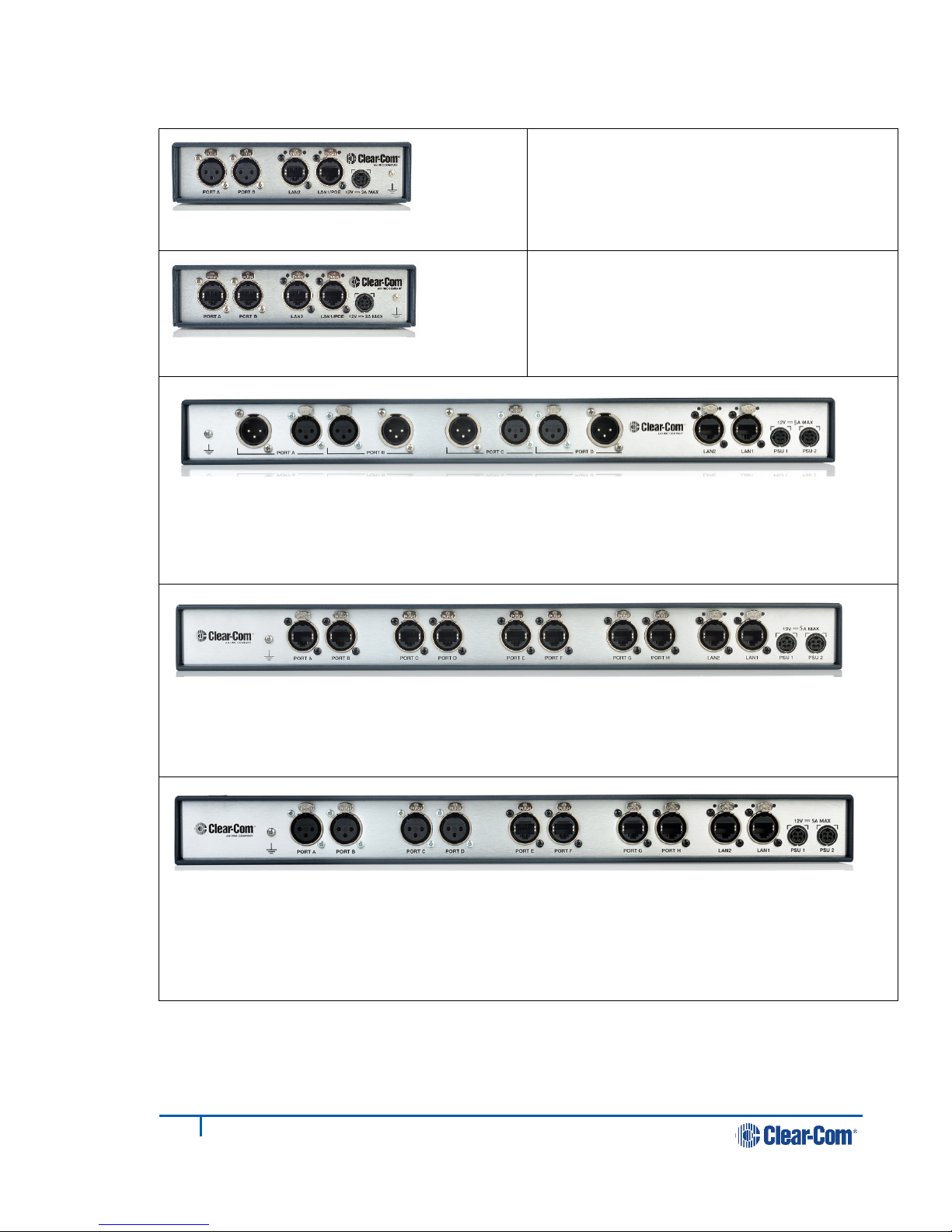
1.1 LQ and LQ-R models
LQ-2W2
Throw-down unit
Two 2-wire partyline connectors (XLR F)
LQ-4W2
Throw-down unit
Two 4-wire connectors (RJ45, etherCON)
LQ-R2W4 1 RU unit
Four 2-wire ports, each with a male and female connector. (XLR)
Dual redundant power supply connectors
LQ-R4W8 1 RU unit
Eight 4-wire connectors, (RJ45, etherCON)
Dual redundant power supply connectors
LQ-R2W4-4W4 1 RU unit
Four 2-wire connectors (XLR F)
Four 4-wire connectors (RJ45, etherCON)
Dual redundant power supply connectors
9
399G116 Rev D
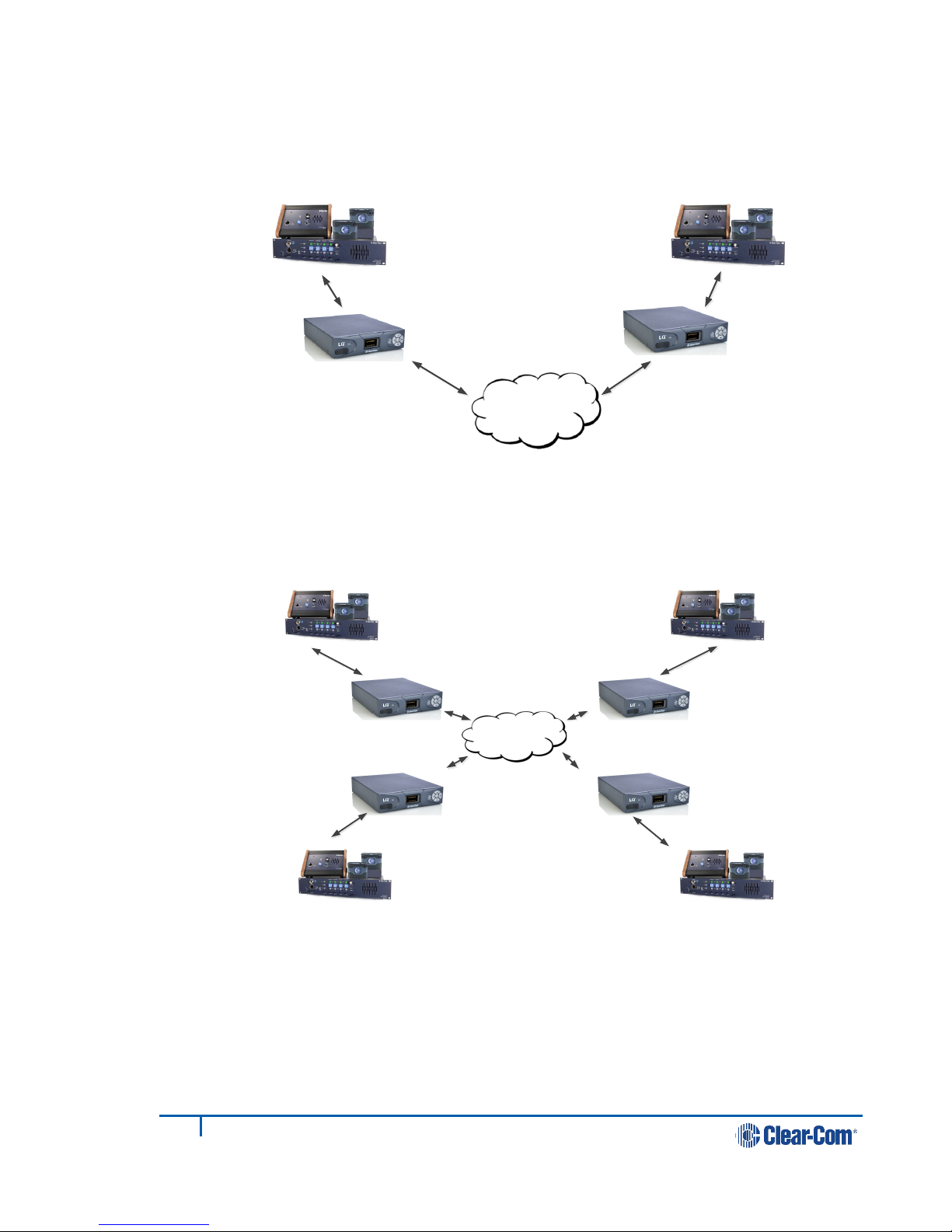
1.2 Basic example applications
Figure 1-1 Partyline to partyline (2-wire connection)
Figure 1-2 Partyline to partyline (2-wire connection). 8 ports,
2 per LQ unit
LAN, WAN,
Internet
LAN, WAN,
Internet
10
399G116 Rev D
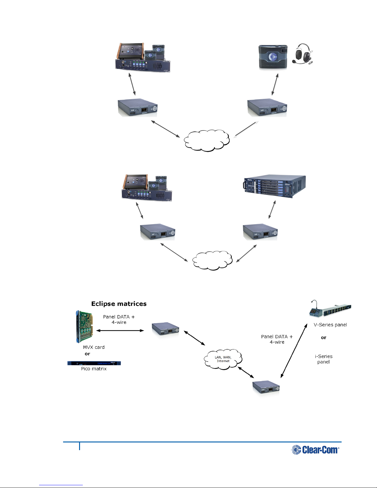
Figure 1-3 Partyline to beltpack
Figure 1-4 Partyline to matrix (2-wire to 4-wire)
Figure 1-5 Panel data over 4-wire connection. Replaces VoICE 2.0 product.
Note: Panel data is passed between a pair of LQ devices, providing a 4-wire direct
connection between two ports.
LAN, WAN,
Internet
PoE or local
power
LAN, WAN,
Internet
LQ 2W LQ 4W
11
399G116 Rev D
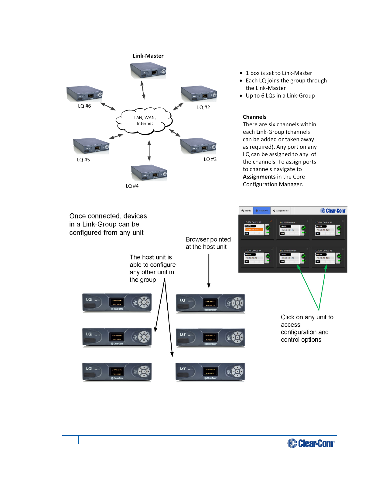
1.3 Link-Group
Figure 1-6 A Link-Group
Figure 1-7 Configuring a Link-Group from any device
Note: The Core Configuration Manager (the Web-based management interface) for any
unit can be reached either directly, by entering the IP address (displayed on the
front of the unit) into a browser address field or via the Overview page of any unit
in the Link-Group.

12
399G116 Rev D
1.4 Example advanced application
Figure 1-8 Example application, partyline and 4-wire direct (panel data)
See 11.4 Example audio assignment via a Pico matrix for example audio
routes for this setup.
13
399G116 Rev D
2Basic setup (LAN)
2.1 Setting up your LQ environment
Prepare your environment by gathering the following equipment:
•LQ units (LQ #1 and LQ #2)
•(2) provided power supply units (PSUs)
•(2) Straight-through Ethernet cables
•(1) Network connection with dynamic host control protocol (DHCP) server
present
•(2) 2-wire or 4-wire devices to provide an audio connection to each LQ
1) Using the Ethernet cable, connect LQ #1 to LQ #2 using either using either
LAN port on the rear of the unit.
2) Using another Ethernet cable, connect LQ #1 to your DHCP enabled network.
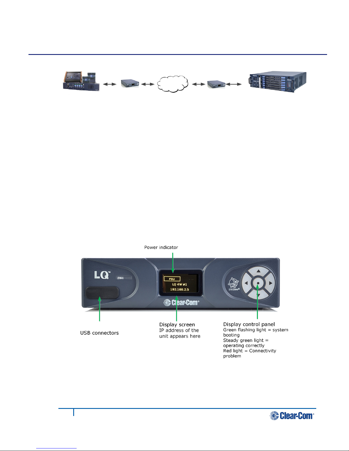
Figure 2-1 LQ device front panel display (4-Wire)
Note: The IP address will be allocated by DHCP (default mode). In the event
that the network does not serve DHCP or there is no network
connection, the IP address will revert to a link-local address. See 8
Link-local environments for more information.
LAN,WAN,
Internet
4-wire
2-wire

14
399G116 Rev D
3) Connect the provided PSU to each LQ device. Each device will display an IP
address on the front panel display.
4) Connect audio equipment to Port Aof each LQ device.
Figure 2-2 Basic setup
2.2 Accessing the Core Configuration Manager (CCM)
From a computer, open a Web browser. Enter the IP Address as displayed on the
LQ #2 device in the address field of the Web browser (Chrome, Safari, Firefox, IE,
Opera). This takes you to the Core Configuration Manager.
Note: Default username and password for the CCM: admin, admin.
1. Connect LQ #1 to
LQ #2 using either
LAN port
LQ #1
LQ #2
2. Connect DHCP
enabled server to
either LAN port
3. Connect
power supply
4. Connect audio
equipment
15
399G116 Rev D
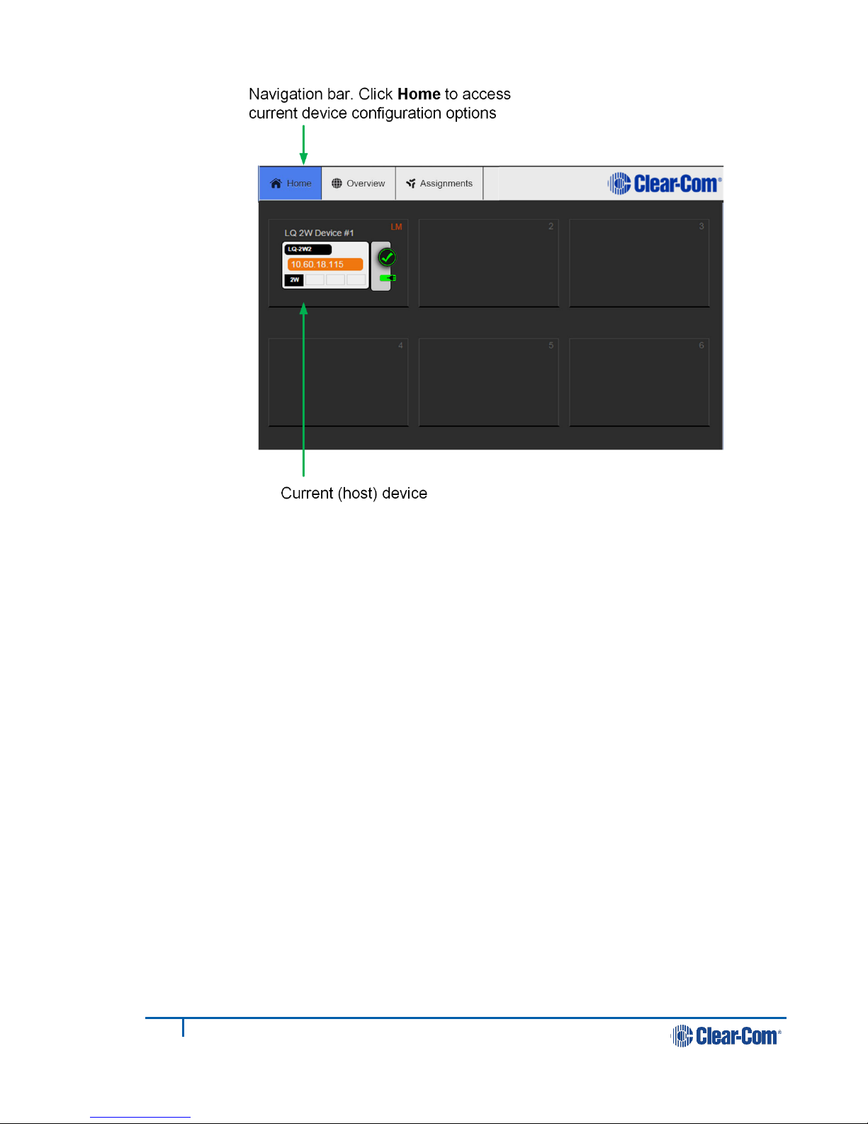
Figure 2-3 Core Configuration Manager
2.3 Create a Link-Group
Before linking units together, one LQ device must first be designated as the Link-
Master. This is accomplished by setting that device's role to Link-Master. Every
other LQ device within the Link-Group will then be set into a Link-Member role
which allows the linking of those units directly to the Link-Master.
In this example, LQ #1 will be left as Link-Master (default configuration) and LQ
#2 will be linked to it.
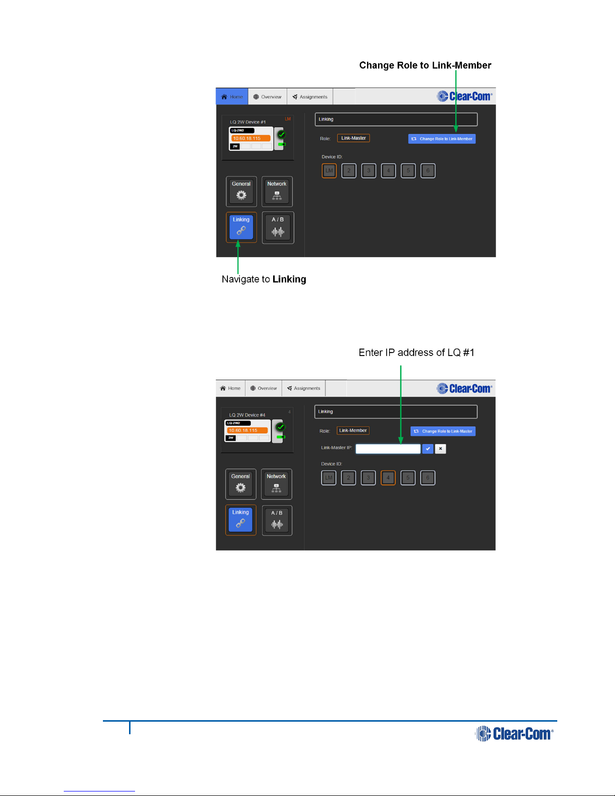
1) Navigate to Home > Linking on the CCM of LQ #2.
2) Click Change Role to Link-Member.
16
399G116 Rev D
3) Within the Master IP address field, enter the IP address as displayed on the
LQ #1 device. Click on blue check mark or <ENTER> key to submit.
17
399G116 Rev D
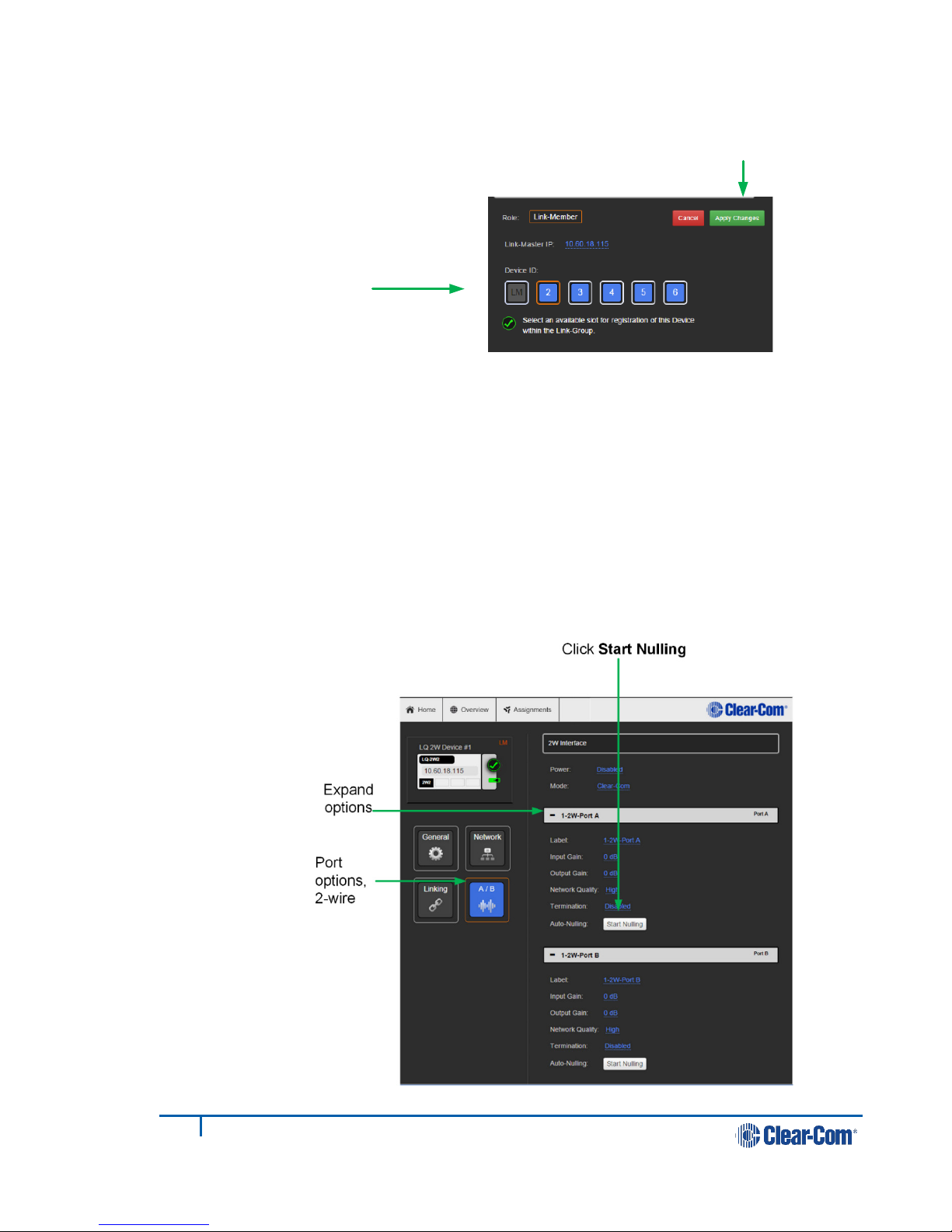
4) Select an available device ID (highlighted in blue).
5) Click Apply changes.
LQ #1 and LQ #2 will now be linked.
6) Navigate to the Overview page (top navigation bar). Both LQ devices should
be displayed on this page.
7) Before continuing, if either LQ device is a LQ-2W2 model, auto-null both
ports. For each device: within the General page, navigate to A/B.
8) Expand port sections (A and B) and click on the Auto-Nulling button for each
port.
Select an available device
ID (highlighted in blue)
Apply Changes
18
399G116 Rev D
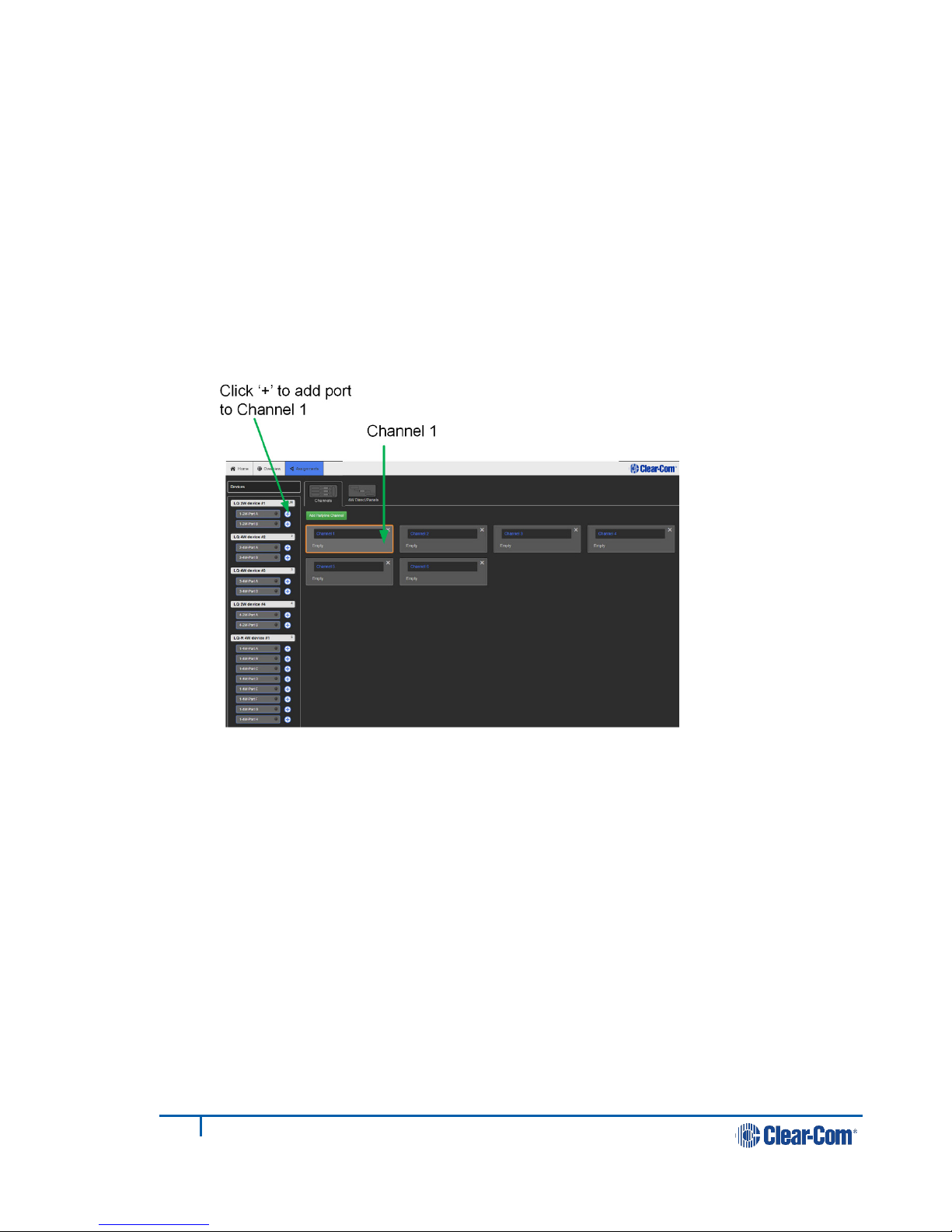
2.4 Assigning ports to a channel
1) Click on the Assignments button within the navigation bar.
2) Select the Channel tab.
3) Add Port A on each device to Channel 1 by clicking on the +symbol to the
right of each port.
You should now be able to pass audio and call/RMK signaling to/from Port A
on each device.
Note: Channel 1 must be selected before audio can be assigned to it. This is
shown by an orange highlight.
19
399G116 Rev D
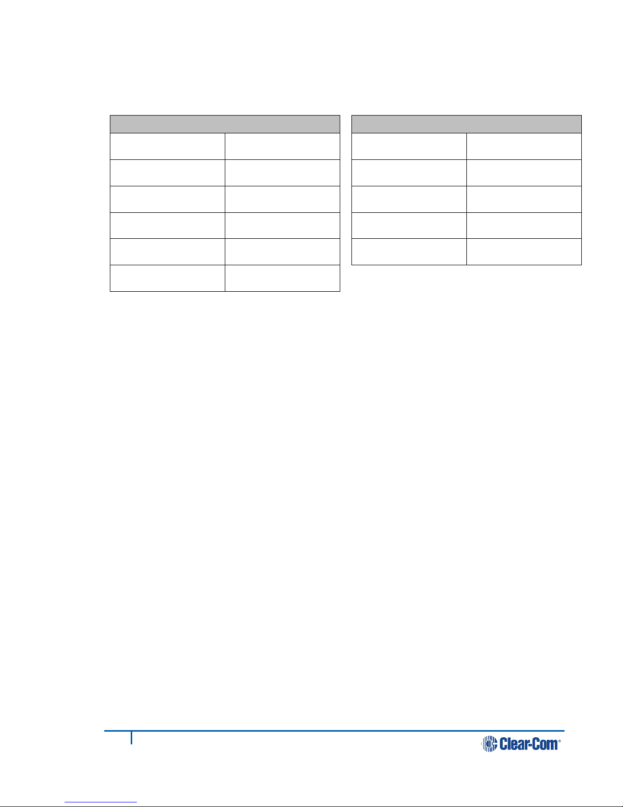
2.4.1 Interface port settings
From the LQ Core Configuration Manager go to Overview > A/B. The LQ factory
default settings are shown below.
2W
Power Disabled
Mode Clear-Com
Input/Output gain 0dB
VOX mode Disabled
Network quality High
Termination Disabled
4W
Input/Output gain 0dB
Network quality High
VOX mode Disabled
Port function To Matrix
Baud rate 19200 (Eclipse)
20
399G116 Rev D
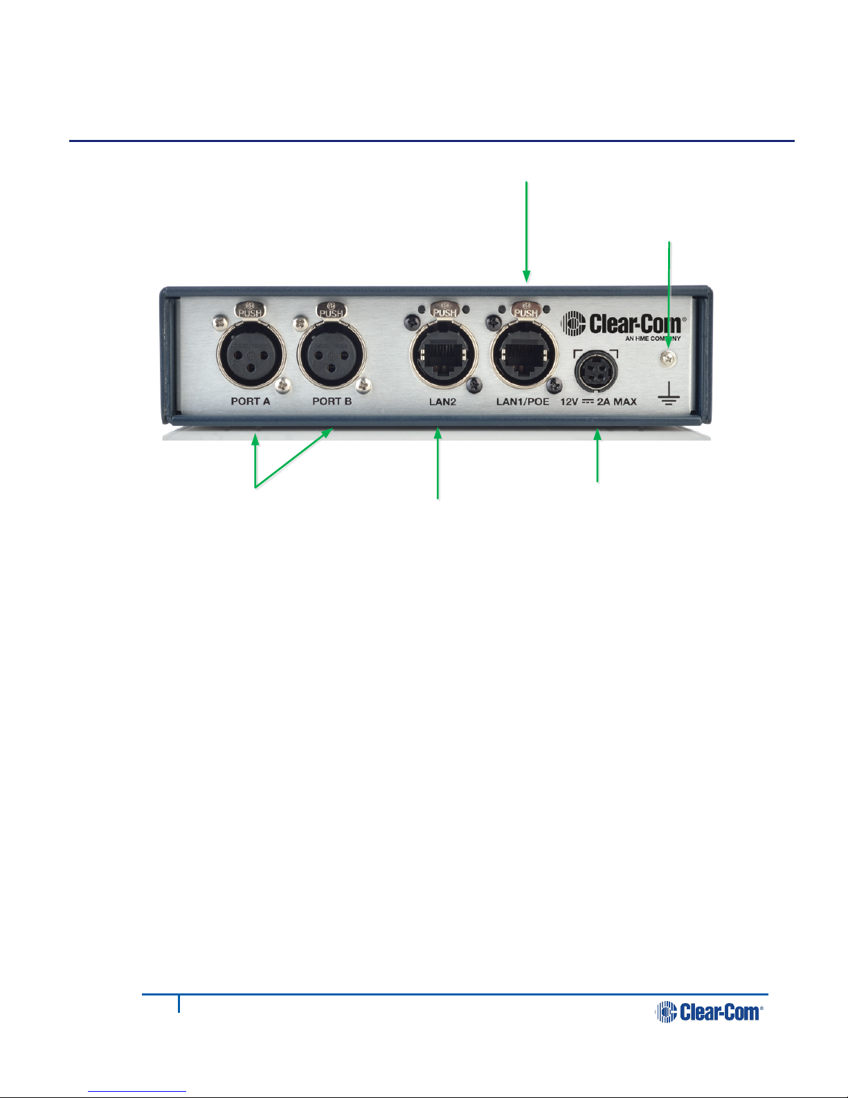
3Powering your LQ™
Figure 3-1 LQ unit rear panel (2-wire device)
3.1 Using the power supply unit (PSU)
•LQ units are supplied with a 24 watt sleeve-locking power connector.
•LQ-R 1RU units are supplied with two 60 watt sleeve-locking power
connectors. Use either power connector, or both to guard against one
power supply failing.
Note: When connecting the sleeve-locking power cable, be sure to push until the
connector locks into the device.
3.1.1 Understanding power display icons
You will be able to see the power status of your device is from:
•The front panel of the unit
•The device icon in the web based configuration tool (the CCM).
These indicators will show if the unit is using PoE or the PSU (LQ throw-down
units), and which of the two power supplies (or both) are in use for the LQ-R units.
Audio ports (2W or 4W) LAN2 connector
LAN1/PoE connector
Sleeve-locking
power connector
Grounding screw
Other manuals for LQ series
3
Table of contents
Other Clear-Com Accessories manuals


Popular Accessories manuals by other brands

Adler
Adler AD 8077 user manual

Balluff
Balluff BTL7-S5 B-M Series Condensed guide

Endress+Hauser
Endress+Hauser Chloromax CCS142D operating instructions

Altec Lansing
Altec Lansing 800 HF DRIVER Reference

PLENY
PLENY 301 Assembly & user instructions

PCB Piezotronics
PCB Piezotronics 010M144 Installation and operating manual
 Specifications")


