Phone: 714-751-0488
Fax: 714-957-1621
P.O. Box 1306
Newport Beach,
California 92663
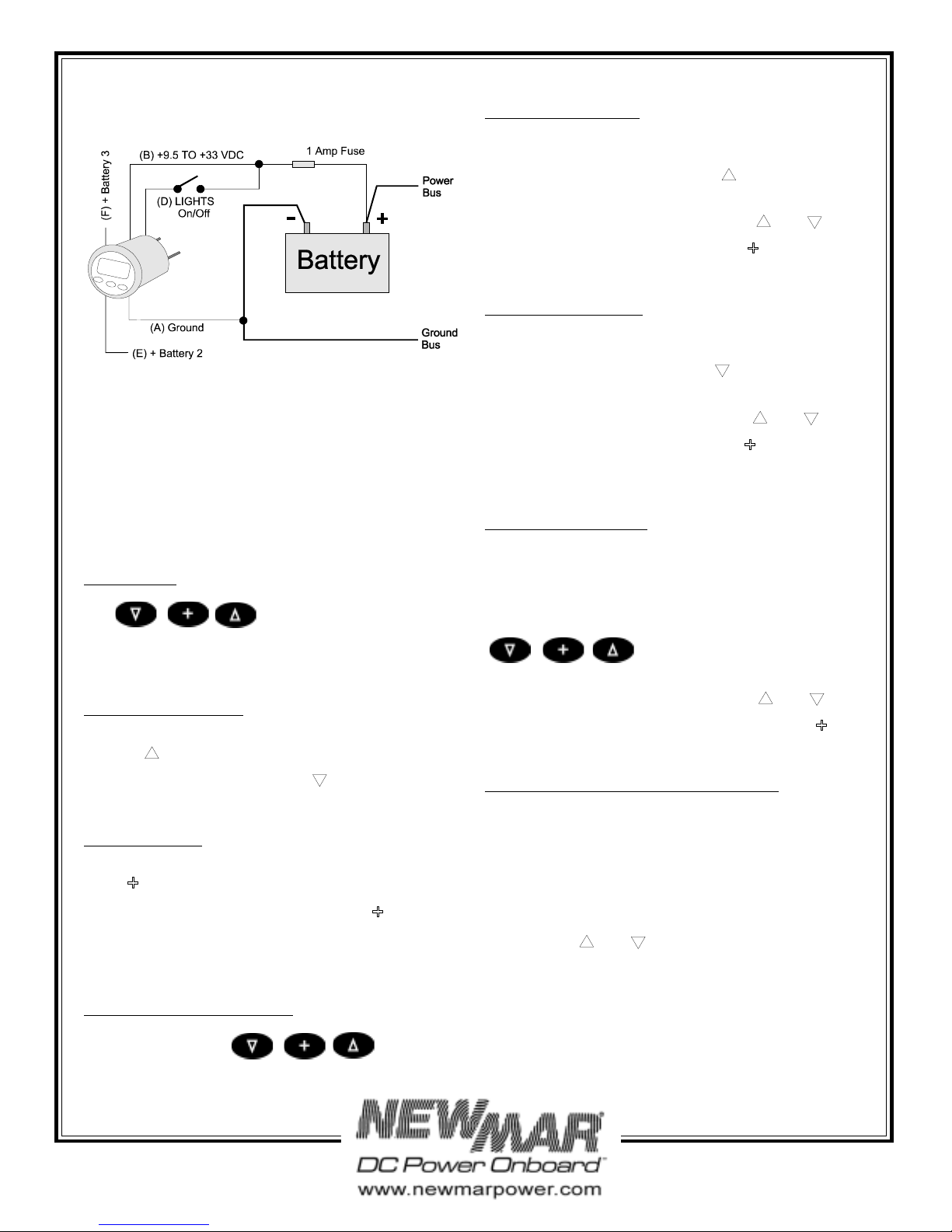
FIGURE 3
Carefully check all your wiring against that shown in
FIGURES 2 and 3. If everything is wired correctly you can
mount the DCV in the instrument hole. Be sure the bulkhead
gasket is in place and use only finger tension to tighten the
bracket hold-down nuts. Do not overtighten the bracket or
you may damage the case - do not use tools to tighten the
nuts.
Operation
Key Functions
The keys are used to select what to
display, backlights, calibrate volts/amps, turn alarms on/off,
and set alarms values. New information is automatically
saved to memory.
Turning Alarms ON/OFF
Press the key 1/2 second to turn alarms ON. The Battery
(1, 2, or 3) icon will blink. Press the key 1/2 second to
turn the alarms OFF.
Backlight Intensity
Press the key 1/2 second to adjust the backlight level for
night-time viewing. Each time you press the key 1/2
second, the level will get brighter 1, 2, 3, 4, OFF, 1, 2...etc.
Screw terminal pin (D) must be switched on for the backlights
to work.
Display Volts for Battery 1, 2, or 3
Quick press one of the keys to select
Battery 1, 2, or 3.
Setting High Volts Alarm
Select the battery (1, 2, or 3) for which you wish to set the
High Volts Alarm. Press and hold the key for ten (10)
seconds. You will hear a beep and the High Volts alarm value
for that battery will be displayed. Use the and keys
to set the desired alarm value. Press the key to save the
High Volts Alam value to memory.
Setting Low Volts Alarm
Select the battery (1, 2, or 3) for which you wish to set the
Low Volts Alarm. Press and hold the key for ten (10)
seconds. You will hear a beep and the Low Volts alarm value
for that battery will be displayed. Use the and keys
to set the desired alarm value. Press the key to save the
new alarm value.
Calibrating the Instrument
The DCV is calibrated at time of manufacture for 12V battery
banks, but can be calibrated at any time by using the front
panel keys. Battery 1, 2, or 3 can be independently calibrated.
To calibrate the voltmeter, press and hold down one of the
keys for three seconds (to calibrate battery 1, 2, or 3) while
applying power to the instrument. Use the and keys
to make the displayed value read correctly. Press the key
to save the calibration data to memory.
Selecting NMEA 0183 or External Alarm Output
The DCV comes factory pre-set to output NMEA 0183
compatible serial data. If you do not need this feature or
would rather have an external alarm output on screw terminal
(C), you can do so as follows.
While viewing battery voltage (any battery), press and hold
down both the and keys for 10 seconds (until you
hear a long beep). This operation switches the output mode
between NMEA 1083 and External Alarm. The new output
mode is automatically saved to memory.
When the external alarm output is activated, a 5V signal (10
mA Max.) is output on screw terminal (C).
12 3
12 3
1 2 3


