NewMar PE Series User manual

15272 Newsboy Circle
Huntington Beach
California 92649
Phone: 714-751-0488
Fax: 714-896-9679
E-Mail: [email protected]
PoweringTheNetwork.com
PE Series
Annunciator Panel
Installation/Operation Manual
Model: AP-8000B
Section Page
Safety Information........................................... 1
1.0. Circuit Board Illustration........................... 2
2.0. General Information................................. 3
3.0. Installation and Wiring............................. 4
4.0. Programming and RS-485 Features......... 6
5.0. Summary Alarm Option (Auto Dialer)..... 7
6.0. RS-485 & Master Remote Operation... 7
7.0. Battery Back-up Option (6 Volt DC).......... 8
8.0. Specifications............................................ 8
9.0. Regulatory Information............................ 9
10.0. Troubleshooting...................................... 9
11.0. Limited Warranty.................................... 9
12.0. AP-8000B Power Source Options............ 10
Wiring Diagram............................................... 11
M-AP8000B
As of 110320

15272 Newsboy Circle
Huntington Beach
California 92649
Phone: 714-751-0488
Fax: 714-896-9679
E-Mail: [email protected]
PoweringTheNetwork.com
Safety Information
FOR COMMERCIAL USE ONLY
CAUTION
Up to 60 Volts DC may be present on the terminals.
DO NOT SHORT ACROSS THE POWER SUPPLY TERMINALS
• Keep fingers and all metal objects from power terminals and wires.
• Use insulated hand tools.
• Recommended: When this device is connected to an alarm panel, place the alarm system in “Test Mode” prior
to servicing.
CAUTION: Disconnect power before attempting to service or repair this product.
This device must be installed in accordance with all applicable electrical and building codes.
NOTICE: No user-serviceable parts inside. Refer all repairs to qualified service personnel.
1

15272 Newsboy Circle
Huntington Beach
California 92649
Phone: 714-751-0488
Fax: 714-896-9679
E-Mail: [email protected]
PoweringTheNetwork.com
1.0 Circuit Board Illustration
1 2 3 4
1 2 3 4
INPUT POWER
9-60 VDC
AP-8000
USE 2A FUSE ONLY
RESET
EXPANSION
PORT
RS-485
AC
POWER
FAILURE
LOW
BATTERY
30%
CHARGER
FAILURE
BDA
FAILURE
ANTENNA
FAILURE
ALARM
6
ALARM
7
ALARM
8
N/O
N/C
COM
N/O
N/C
COM
N/O
N/C
COM
N/O
N/C
COM
N/O
N/C
COM
N/O
N/C
COM
N/O
N/C
COM
N/O
N/C
COM
9-60V DC Input,
Sect. 3.2
newmar
PROPERTY OF NEWMAR
Alarm LEDs (8),
Sect. 3.7
LED 9
LED 10 LED 11
Micro-processor
Sect. 10.0
Sect. 4.2
Sect. 3.4
1 2 3 4
6V
Baery
RUN
5V
ALARM
BUZZER
+TERM. IN
Alarm Contact.
Sect. 7.3
1A
SILENCE
ALARM INPUTS
FROM BDA/BBU
Alarm Silence
PBuon,
Sect. 3.6
Reset Pus
Contact Factory
Alarm Input Disable
Jumper Pins, Sect. 3.5
2A Input Fuse,
Sect. 3.2
Fuse, Sect. 7.0
1 2 3 4 5 6 7 8
Refer to tealarm lnon
te insie of te oor
1 2 3 4 5 6 7 8
RS-485 LED
ors, Sect. 6.3
Connector, Sect. 7.0
SL1 Ter
Jumper,
Sect. 6.4
EOL
Resistor
for FACP
(8),
Form C
Alarm
Outputs
to FACP
(8),
Sect. 3.7
Terminal Block,
Sect. 3.3
Sect. 6.1
Sect. 3.1
Sect. 10.0
Sect. 3.7
2

15272 Newsboy Circle
Huntington Beach
California 92649
Phone: 714-751-0488
Fax: 714-896-9679
E-Mail: [email protected]
PoweringTheNetwork.com
2.0 General Information
Features:
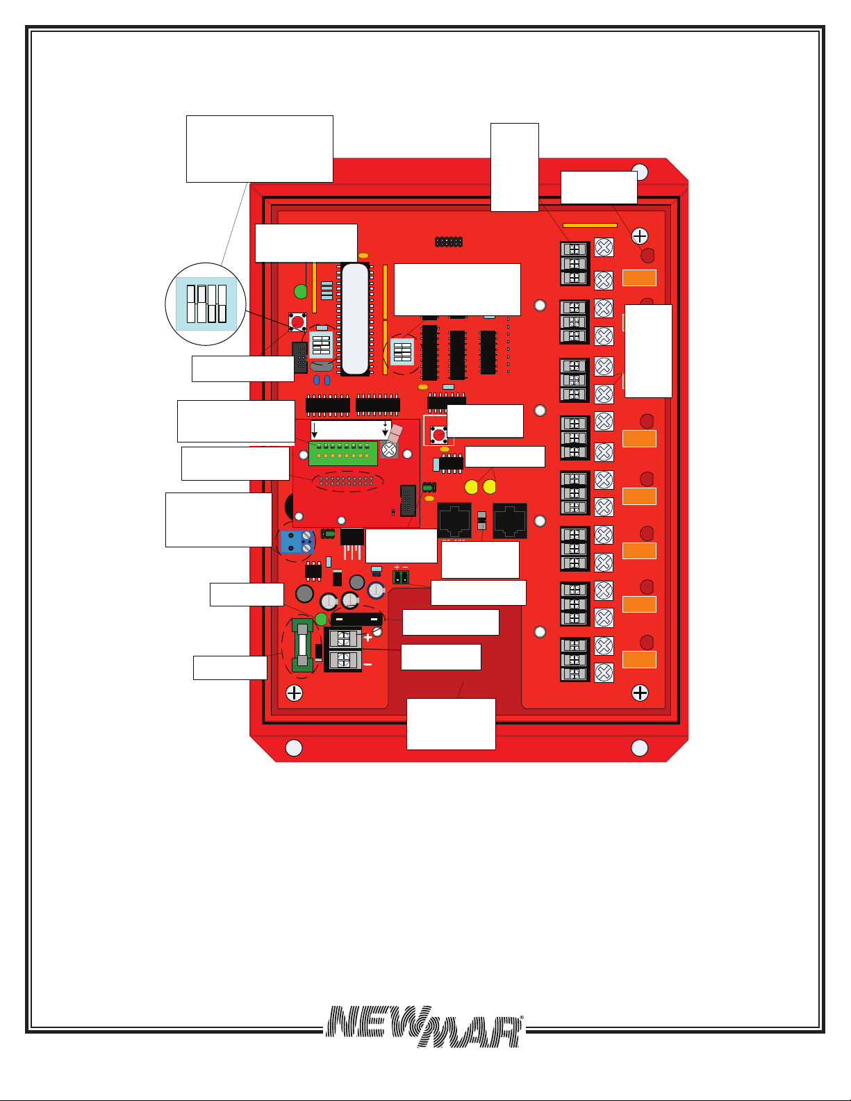
2.1. The AP-8000B is a Microprocessor controlled fire alarm annunciator panel for use with In-building 2-Way Emergency
Radio Communication Enhancement Systems (ERCES) required by the National Fire Protection Agency (NFPA 1221).
It monitors the alarms of the Bi-Directional Amplifier (BDA) and Battery Back-up Unit (BBU) and provides visual and
audible alarms as well as communicates these alarms to the fire control panel viaup to eight sets of form C alarm
contacts.
2.2. Alarm inputs: 8 alarm input capacity to accommodate new UL2524 alarm point requirements. Five inputs are
standard/labeled on face of panel and the panel can accept an additional three alarms as required by new UL
Standard 2524 (additional labels included).
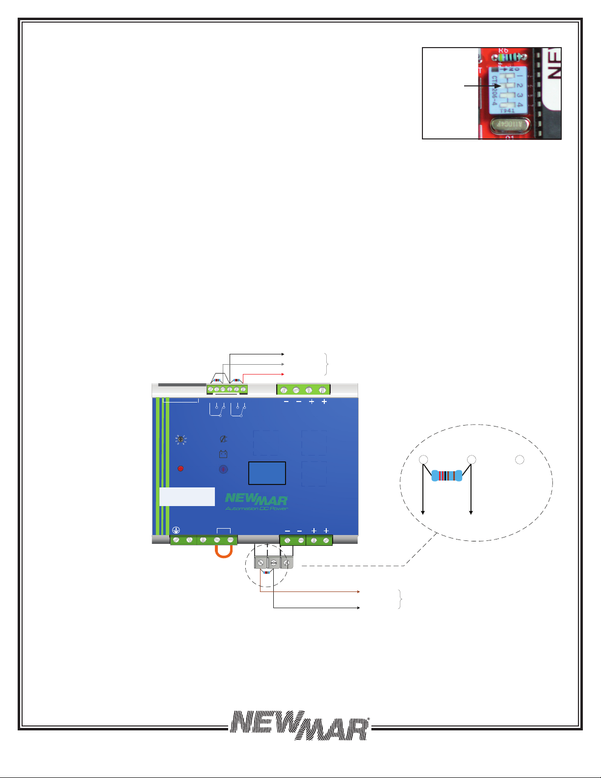
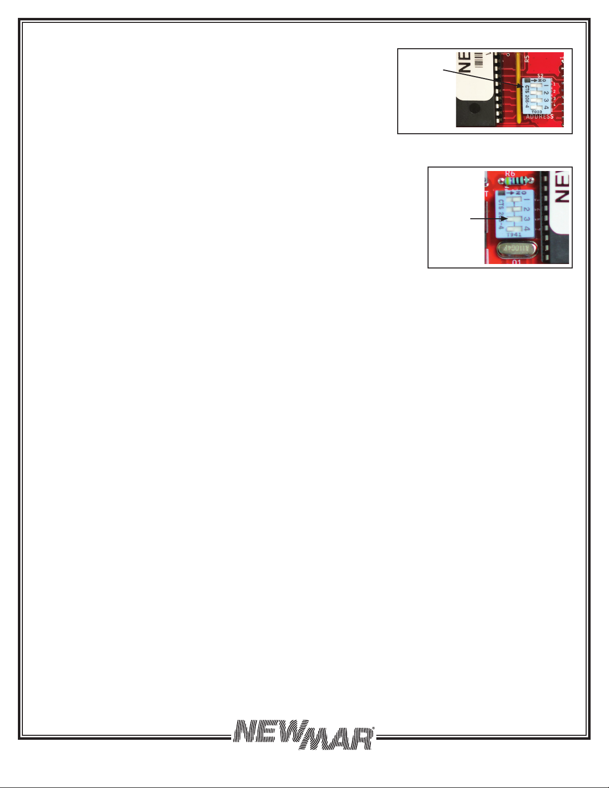
2.3. Alarm Input Wiring Supervision: continuously monitors alarm input wiring for faults, selectable for either Normally
Open or Normally Closed alarm contact monitoring. Immediately flashes the alarm LED that has faulted and
produces an audible alarm (beeping) whenever an alarm input wire becomes broken or shorted. End of line resistors
(2.2 k Ohm 1%,1W resistors provided) are installed at the BBU & BDA alarm contacts to enable this feature. Enabling of
NO or NC monitoring is done by simple DIP switch placement.
2.4. One model, operates on 9-60V DC input
2.5. Easy set-up and installation:
• All programming done via 8 DIP switches - no trim pots to turn taking out guess work if the pot is set properly.
• Alarm panel end of line resistor landings provided for alarm panel connection.
• Cable feed thru locations: Drill locations include bottom or sides. In addition, space is provided on the lower back
panel of enclosure for rear cable/conduit access. One ½” and one ¾” liquid tight cord grips included.
• Three jumpers provided to allow disabling of alarms that are not in use- no zero ohm resistors required.
2.6. Master/Remote Operation: Up to 15 additional AP-8000B’s can be connected in a daisy chain fashion using a
standard Cat 5 cable. A selector switch allows the Master’s power source to be provided downstream to power the
remotes via POE, eliminating the need to run separate power feeds to each Remote. Exception: If using 6 volt battery
back-up at at Remotes, a separate input power is requied at each Remote.
2.7. Additional optional alarms:
• Loss of 5 volt DC internal power Alarm
• Alarm input # 8 can be programmed to provide a summary alarm for activating an auto dialer.
2.8. Enclosure: UL Listed NEMA 4 box ensures no water penetration during an emergency when used with liquid tight cord
grips or conduit fittings.
2.9. Built in 6 volt battery charger: Add optional 6 volt battery (P/N: 591-0126-0) for internal battery back-up. Useful for
120V AC systems where an AC adapter is used to power the annunciator panel or to meet AHJ requirements for
separate, internal annunciator battery back-up. See Section 7 for more information.
2.10. Security: AP-8000B Features a ¼ turn door latch which can be changed easily and quickly to either a quarter-turn
keylock, or padlock lock, when required to deter unauthorized access.
2.2 Materials Provided:
1 ea. AP-8000B Annunciator Panel
1 ea. Installation/Operation Manual
1 set of UL 2524 Alarm Labels:
• “Active RF Device Failure”
• “Active Component Failure”
• “Donor Antenna Failure”
4 ea. #10 x 3/4” Philip Head Mounting Screws
3 ea. Small Programming Jumpers, installated in alarm input positions #6, #7, #8
1 ea. In-line Fuse Holder
1 ea. 2 Amp Input Power Fuse
1 ea. 1/2” NPT Cord Grip (IP68)
1 ea. 3/4” NPT Cord Grip (IP68)
8 ea. 2.2 K ohm, 1%, 1 Watt end-of-line (EOL) termination resistors
1 ea. 11” x 17” Mounting Template
1 ea. Two position pluggable terminal block for 6 volt battery (option)
2 ea. Female Fast-on (0.187”) crimp connector for 22 - 18 AWG for optional 6 volt battery (P/N: 591-0126-0)
2 ea. #6 crimp ring lug for 22 - 18 AWG for making GND/RETURN screw wire connection
3

15272 Newsboy Circle
Huntington Beach
California 92649
Phone: 714-751-0488
Fax: 714-896-9679
E-Mail: [email protected]
PoweringTheNetwork.com
4
The Annunciator provides one “Form-C” relay output for up to (8) eight alarm conditions to the building’s main fire alarm
panel control panel (FACP) or other device. Typical UL-2524 installations require at least the following alarm conditions to
be annunciated:
3.0 Installation & Wiring
3.1 Wall-Mount Installation:
1. One 1/2” NPT and one 3/4” NPT liquid tight cord grips are provided. Choose a location to drill the appropriate size
hole (1/2” NPT = 7/8” and 3/4” = 1-1/8”). Recommended cord grip hole drill ocations are the two sides, bottom and
rear in the opening provided at the bottom of the circuit board. CAUTION: Remove drill shavings before powering
AP-8000B or severe damage can occur.
2. The AP-8000B is designed to be wall mounted. Select a suitable location in accordance with any approved building
plans or as specified by the Authority Having Jurisdiction (AHJ).
3. Affix the enclosure to the wall using the supplied mounting screws.
4. Flush Mounting: If mounting inside a wall space, ensure adequate space to all opening and closing of the door.
If required, alternative mounting arrangements may be used but avoid drilling new holes in the front cover door.
3.2 Wiring
Power Source Wiring Options: (9-60V DC Input, <100 mA)
Reverse Polarity protection note: If the DC power source is connected reverse
polarity it will simply blow the 2 amp slow blow fuse to the left of the input
power terminal block and protect the annunciator. Replace with Littlefuse
#.33002 MXP or equivalent.
The DC input terminal block is located in the lower left hand side corner of
circuit board and will accept 12 to 22 AWG wire size. Maximum current draw
is 100 milliamps.
Option #1 BBU DC Power: Connect annunciator DC power input terminals
to BBU DC output. Use provided inline fuse holder & 2 Amp fuse wired on the
+ VDC power at the BBU output terminal blocks. See Wiring Diagrams on Page 10, Figures 8 and 9.
Option #2 120 VAC Power Source: Use a 120V AC to 12V DC AC wall adapter, 1 amp size recommended. Note: Battery
back up is recommended whenever powering the annunciator panel from 120V AC power. See battery 6 volt battery
back-up Section 7 for details.
3.3 Alarm Input Wiring from BBU & BDA General Info: (Refer to Figure 2)
• Connect alarm input wiring to the 8-position green terminal block located on left hand side of circuit board which
accepts wire sizes 16 to 24 AWG.
• Strip wire back aproximately 3/8”, press down on orange lever with a small screwdriver to open the spring loaded
opening, and insert wire end into top opening of terminal block and release the orange lever. Verify connection by
tugging on wire and ensuring wire is secure.
• Wiring tip: Jumper the ‘C’ (COMMON) Alarm contacts at the BBU and BDA in parallel and run a single Common wire to
the annunciator panel GND/Return screw terminal.
CAUTION: Do not simultaneously apply power to both the main Input Power Connector and the above terminals. Doing so
may damage the annunciator or any external equipment connected to it.
Figure 1: AC Power Input Terminal Block
DC Power Input
Terminal Block
1. Loss of AC power
2. Low battery, indicating the battery
has discharged by 70%
3. Charger failure
4. BDA Failure
5. Antenna Failure
6. Active RF Device Failure*
7. Active Component Failure*
8. Donor Antenna Failure*
* Labels included
Figure 2: 8 Position + Ground/Return Screw
Terminal Block
Plug-in
Jumpers
Ground
Screw
8 Position
Terminal
Block
Not used - Expansion
POSITION # FUNCTION
1 Alarm Input #1/AC Power Fail
2 Alarm Input #2/Low Battery
3 Alarm Input #3/Charger Fail
4 Alarm Input #4/BDA Fail
5 Alarm Input #5/Antenna Fail
6 Alarm Input #6
7 Alarm Input #7
8 Alarm Input #8
Screw (#6 - 32) GND/Return

15272 Newsboy Circle
Huntington Beach
California 92649
Phone: 714-751-0488
Fax: 714-896-9679
E-Mail: [email protected]
PoweringTheNetwork.com
3.4 Alarm Contact Type Setting: The annunciator monitors up to 8 alarm contact s from
the BBU and BDA. The AP-8000B can be set to monitor all contacts in either Normally
Open or Normally Closed position. Set the Function DIP switch #2 (see Figure 3) as
follows:
OFF = Contact closure initiates the alarm so wire to BBU/BDA NO Normally Open
contacts when powered and no alarms (Factory Default)
ON = Contact open initiates the alarm so wire to BBU/BDA NC Normally Closed
contacts when powered and no alarms
See Section 4.0 for more information on the Function Dip Switch
3.5 Alarm Disable Jumpers: Alarms #6 (Active RF Device Failure), #7 (Active Component Failure) & #8 (Donor Antenna
Failure). If not wiring these three alarms leave the three small jumpers installed at the factory. Remove them if you intend
to connect alarms #6 thru #8.
End of Line Resistors (EOL)
In order to supervise input wiring for faults, an end of line resistor (2.2K ohm, 1 watt, 1%), resistor (included), must be
installed at the BBU and BDA for each alarm contact.
End of Line (EOL) Resistor Wiring for Non-UL PE (BBU) models where resistors connect directly to the BDS-DIN-UPS XX-XX
charging unit. BDS alarm contacts state shown on front panel are shown with no power or battery connected to the BDS-
DIN UPS. As such Normally Open is Normally Closed & Normally Closed is Normally Open when BBU is powered up and
has no alarms.
Note: Wiring diagrams for EOL resistor wiring for Non-UL PE (BBU) follows. See Section 12 on page 10 for wiring diagrams for
EOL resistor wiring for Newmar UL PE (BBU).
Figure 4A: End of Line Resisitor Installation
MIN MAX
L N (3) (4)
BATTERY
BATTERY
CHARGING LEVEL
i
AC
FAIL
LOW BATTERY
OR BATTERY
REPLACEMENT
DIAGNOSIS
BATTERY
START
TIME
BUFFERING
0
5
A
U
X
3
OUTPUT LOAD
(1) (2)
AC
FAIL
LOW BATTERY
OR BATTERY
REPLACEMENT
5 6 7 8 9 10
JUMPER FOR
115 Vac
BDS DIN-UPS 48-10
OUTPUT: 48Vdc 10A
INPUT: 115-230Vac
T
E
M
P
P
R
O
B
E
C
O
M
M
O
D
B
U
S
(714) 751-0488
Www.automaondcpower.com
Newport Beach, CA USA
Factory Set
BATTERY
SELECTION
NONC
RECTIFIER FAIL
COM
Example Shown:
Model BDS-DIN-UPS 48-10
Low Ba�.
AC Fail
GND/ Return
To the
Annunciator Panel
COM
To AP-8000B
Alarm Input
NC NO
To the
Annunciator Panel
Charger Fail
GND/ Return
Notes:
1) EOL Resistor: 2.2kΩ, 1W, 1%
Note: BDS alarm contacts state shown on front panel are shown
wicted to the BDS-DIN UPS. As
such Normalormallosed and Normalllosed is
NormallOpen when the BBU is powered and has no alarms.
Normally Open Contacts
Example Shown:
Model BDS-DIN-UPS 48-10
5
Function
DIP
Switch
Position
2
Figure 3: Function DIP Switch

15272 Newsboy Circle
Huntington Beach
California 92649
Phone: 714-751-0488
Fax: 714-896-9679
E-Mail: [email protected]
PoweringTheNetwork.com
6
Figure 4B: End of Line Resisitor Installation
3.6 SILENCE Button:
• Press and hold for 2 seconds to activate silence.
• Pressing SILENCE on any annunciator (whether Master or Remote) silences all annunciators for 24 hours.
After 24 hours, the beeper activates again (if there is no change in alarm status), in accordance with UL-2524. If the alarm
status changes while the 24-hour silence is in effect (i.e., a new alarm arrives, or an old alarm condition recovers), the
24-hour silence timer is reset and the beeper sounds. If the SILENCE button is pressed on any annunciator (whether Master
or Remote) while silence is already in effect, the button press is ignored. (i.e., additional time is not added.)
3.7 Connection to the Building’s Main Fire Alarm Panel: (This step is optional.)
The AP-8000B provides (8) Form-C relay outputs that may be connected to the building’s fire alarm control panel (FACP).
A corresponding Red LED will illuminate when the alarm is activated. A corresponding Red LED will illuminate when
the alarm is activated. Confirm with your local building inspector/authority having jurisdiction (“AHJ”) whether such
connections are permissible in your area.
Each Form-C alarm output relay has a separate wiring terminal. These terminals are located along the right-hand side of
the circuit board with “Alarm 1” at the top, and “Alarm 8” at the bottom.
The alarm relay terminals accept wire sizes 18 - 22 AWG.
End Of Line Resistors: If desired, an in-series “End of Line” supervision resistor may be installed on the screw terminals
adjacent to the relays. Any EOL resistors placed here will be “in-series” with the Common terminal of the Form-C relay. If
these EOL terminals are not used, they must be shorted across, so that the Common terminal of the relay is presented to
the FACP wiring block
4.0 Programming and RS-485 Features
4.1 Function Switch: 4-Position DIP switch (left of processor):
Switch-1 = Beeper OFF/ON (Off = No beeper, On = Beeper will sound on alarms)
Switch-2 = Relay contact selection (ON=Normally Closed/Contact Open activates alarm, OFF=Normally Open/Contact
Closure activates alarm)
Switch-3 = Normal or summary alarm (OFF = Normal Donor Antenna Failure Alarm operation, ON = Summary Alarm or
Auto-Dialer Activation). See Section 5 ‘Summary Alarm Option (Auto-Dialer) for more information
Switch-4 = Selects Master/Remote (Off = Master, On = Remote)
MIN MAX
L N (3) (4)
BATTERY
BATTERY
CHARGING LEVEL
i
AC
FAIL
LOW BATTERY
OR BATTERY
REPLACEMENT
DIAGNOSIS
BATTERY
START
TIME
BUFFERING
0
5
A
U
X
3
OUTPUT LOAD
(1) (2)
AC
FAIL
LOW BATTERY
OR BATTERY
REPLACEMENT
5 6 7 8 9 10
JUMPER FOR
115 Vac
BDS DIN-UPS 48-10
OUTPUT: 48Vdc 10A
INPUT: 115-230Vac
T
E
M
P
P
R
O
B
E
C
O
M
M
O
D
B
U
S
(714) 751-0488
Www.automaondcpower.com
Newport Beach, CA USA
Factory Set
BATTERY
SELECTION
NONC
RECTIFIER FAIL
COM
Low Ba�.
AC Fail
GND/ Return
To the
Annunciator Panel
To the
Annunciator Panel
COM
To AP-8000B
Alarm Input
NC NO
Charger Fail
GND/ Return
Example Shown:
Model BDS-DIN-UPS 48-10
Note: BDS alarm contacts state shown on front panel are shown
wicted to the BDS-DIN UPS. As
such Normallis Normalllosed and Normalllosed is
NormallOpen when the BBU is powered and has no alarms.
1) EOL Resistor: 2.2kΩ, 1W,1%
Normally Closed Contacts
Example Shown:
Model BDS-DIN-UPS 48-10

15272 Newsboy Circle
Huntington Beach
California 92649
Phone: 714-751-0488
Fax: 714-896-9679
E-Mail: [email protected]
PoweringTheNetwork.com
7
4.2 Address Switch (see Figure 5): 4-Position DIP switch (right side of processor):
This sets the annunciator address in binary. (0 - 15). Set a unique address for each
annunciator panel. Example:
Remote #1: ON/ON/OFF/OFF
Remote #2: ON/ON/ON/OFF
Remote #3: ON/ON/ON/ON
Remote #4: OFF/ON/ON/ON
5.0 Summary Alarm Option (Auto Dialer)
The AP-8000B can be set to activate relay #8 whenever any one or more of the alarm inputs (#1 - #7) are activated. This
summary alarm can be used to activate an Auto Dialer for example.
To set relay #8 for summary alarm:
1. Disconenct power from AP-8000B
2. Open the door on the front of the AP-8000B
3. Identify DIP switch to the left of the main microprocessor
4. Set DIP switch #3 in the Figure 6
5. Re-connect power to the AP-8000B
6. Test, attach a continuity checker across the NO and COM terminals of relay #8 and
activate any alarm (example: turn BDA Battery back-up (BBU) power battery breaker
in the OFF potion momentarily). Confirm relay #8 activates.
6.0 Master/Remote Wiring & Operation & RS-485
6.1 Connect Wiring:
Up to 16 AP-8000B’s can be connected in a Master/remote configuration. First set the Function DIP switch #4 for
OFF=Master or ON=Remote. Next set a unique address for each unit on the Addressing switch (right side of
microprocessor), reference Section 4.2.
Use a standard Cat. 5 cable to daisy chain master to remotes using the two RJ-45 jacks on each AP-8000B.
To set up a Master/Remote system, a selector switch allows the Master’s power source to be provided downstream to
power the remotes via POE, eliminating the need to run separate power feeds to each Remote. Example: Install one
AP-8000B in the building entry area/lobby and one near the BDA & BBU or on a separate floor. Place the Remote Power
switch in the up position.
6.2 RS-485 Pinout:
• Pin -1: RS485A
• Pin -2: RS485B
• Pin -3: Ground
• Pin -4: PoE+ (Not Used)
• Pin -5: PoE+ (Not Used)
• Pin -6: Ground
• Pin -7: PoE- (Not Used)
• Pin -8: PoE- (Not Used)
6.3 RS-485 LED Indicators:
• LED -10: Illuminates when the annunciator panel is transmitting over the RS-485 Serial Link.
• LED -11: Illuminates when the annunciator panel is receiving serial data from a remote annunciator.
6.4 SL1 Termination:
• SL1 is the termination resistor for the RS-485 Serial Communication Bus.
• With the jumper placed over the left and center pins, the termination resistor is in-circuit. This is for “Master Only”
configurations.
• With the jumper placed over the center and right pins, the termination resistor is out-of-circuit. This is used for Master
and Remote configurations.
Function
DIP
Switch
Position
3
Figure 6: Function DIP Switch
Figure 5: Address DIP Switch
Address
DIP
Switches

15272 Newsboy Circle
Huntington Beach
California 92649
Phone: 714-751-0488
Fax: 714-896-9679
PoweringTheNetwork.com
7.0 Battery Back-up Option (6 Volt DC):
If powering the AP-8000B from a 110V AC BBU 110V AC output or a 110V AC outlet we recommend installing the 6 volt
battery back-up option, see Figure 7.
7.1 Materials Required:
1 x 6 volt, 1.2 AH sealed valve regulated lead acid battery
with F2 terminals (.187”). Newmar p/n 591-0126-0.
1 x Two position ckt. board mating connector -provided
2 x .187” Female Fast-on crimp lugs- provided
2 x 18 to 22 AWG insulated wires, red & black,
approximately 10” length. Installer supplied.
7.2 Wiring:
1. Cut two pieces of 18 to 22 AWG wire size, red & black
recommended approximately 10” in length. Strip both
ends of each wire approximately ¼” and crimp one
each 22-18 AWG .187” crimp female fast-on provided
with AP-8000B on to the end of each wire.
2. Insert the other ends of stripped wires to the two position
green pluggable terminal block provided with the
AP-8000B. Be careful to ensure polarity is correct -
see Figure 7. Positive/red wire should be on the left
side when connector is mated to the circuit board
connector. If battery is connected to the AP-8000B
reverse polarity the ATC-1, 1 Amp fuse will blow and
protect the circuit.
3. Connect the red wire w/female fast-on on to the battery
positive (+) terminal. Connect the black wire w/female fast-on on to the battery negative (-) terminal.
4. Place the 6 volt 1.2 AH battery on the inside bottom of the AP-8000B enclosure and connect the green two position
connector on to the mating connector on circuit board labeled ‘Battery 6 V’. The AP-8000B should power up.
5. Connect a source of DC power to the ’Input Power 9 - 60V DC’ terminal block and energize this power source. Measure
voltage across the 6 volt battery and verify approximately 6.8V DC.
6. Verify battery back-up by disconnecting input power and verify AP-8000B remains powered and there’s no
interruption of operation. Reconnect input power.
7.3 Power Failure Alarm Contact: See Figure 7 for location. Two position plug-able terminal block. Normally Closed when
power to Annunciator is ok, opens upon loss of power. Accepts wire sizes: 14 - 22 AWG.
8.0 Specifications
Subject to Change without Notice
General:
• Microprocessor controlled
• QTY-(8) Form-C, UL-Listed, Small Signal Relays
• “Heartbeat” indicator
• Front panel “Press-to-Test” button
• Easily adapted to fit nearly any situation
• RS-485 Serial Communication for Master/Remote Annunciator panel operation. Master and up to 15 remotes.
• Audible alarm (silenceable: 24 hours)
Cabinet:
• Shipping weight: 8 Lbs.
• Dimensions (assembled): 10” H x 8” W x 4” D
• Environmental Rating: NEMA-4
• Closure: ¼ Turn Twist-Lock
• Color: Red, Color# RAL-3001)
• Form-C, UL-Listed Small Signal Relay
• 2-Amp DC Rating (Resistive)
Electrical:
• 9 - 60V DC
• Input Current Draw: <100mA max.
• Max Power: 4.5 Watts
• Relay switching current: 2-Amp DC (resistive)
• Optional battery: 6 volt, 1.2 amp-hour with 0.187” fast-on terminals (24 hour back-up time)
Power Failure
Alarm
Contact
Battery
Connector
1 Amp
Battery Fuse
Battery (-)
Battery (+)
Figure 7: Battery Back-up
8

15272 Newsboy Circle
Huntington Beach
California 92649
Phone: 714-751-0488
Fax: 714-896-9679
E-Mail: [email protected]
PoweringTheNetwork.com
9.0 Regulatory Information
California Prop-65 Warning Notice: This product contains lead, a chemical known to the State of
California to cause cancer, birth defects or other reproductive harm. Wash hands after handling
lead products.
Recycling Notice: Please help protect the environment. We encourage all purchasers to recycle their lead-acid batteries.
For the recycling location nearest you, please visit www.call2recycle.org/
FCC Part-15: This device complies with Part 15 of the FCC Rules. Operation is subject to the
following two conditions: (1) This device may not cause harmful interference, and (2) this device
must accept any interference received, including
interference that may cause undesired operation.
10.0 Troubleshooting
This Universal Annunciator is designed and engineered to provide years of service in unattended commercial installations.
With the exception of a single internal 2 amp ceramic fuse, there are no user serviceable parts inside.
In the event the annunciator fails to function properly, there are a few basic system checks that can be performed in the
field:
1) Verify power LED located to the right of the Input Fuse is illuminating. If not illuminating, check 2 Amp input fuse. If fuse
is ok, unplug the battery (if one is installed), and check the voltage at the green battery terminal. It should be 6.95 volts
(+/- 0.15).
2) Check for the green, blinking “Heartbeat” LED light located at the upper left portion of the circuit board. This green LED
blinks under microprocessor control. If the LED is blinking, it means the microprocessor is running and operating
normally. If the Heartbeat LED is not illuminated,or is blinking erratically, there may be a problem with the power
supplied to the device.
3) Verify that all wiring connections to all terminals are clean and tight, and that the wiring is fully under the
terminal screws.
If the above system checks do not resolve the problem, please contact our Technical Support staff for further assistance.
11.0 Limited Warranty
Newmar warrants that the AP-8000B PE Series Annunciator Panel to be free from defects in material and workmanship for
two years from date of purchase. If a problem with your AP-8000B or if you have any questions about the installation and
proper operation of the unit, please contact NEWMAR’s Technical Services Department:
Phone: 714-751-0488 - From the hours of 8:00 a.m. to 5:00 p.m. weekdays, P.S.T.;
Fax: 714-896-9679
E-mail: techservice@newmarpower.com
9

15272 Newsboy Circle
Huntington Beach
California 92649
Phone: 714-751-0488
Fax: 714-896-9679
E-Mail: [email protected]
PoweringTheNetwork.com
Figure 8: Newmar UL Series PE Power Output (All DC Models)
MIN MAX
BATTERY
CHARGING LEVEL
i
AC
FAIL
LOW BATTERY
OR BATTERY
REPLACEMENT
DIAGNOSIS
AC
FAIL
LOW BATTERY
OR BATTERY
REPLACEMENT
5 6 7 8 9 10
123 4
OUT
LOAD BATTERY
Jumper FOR
115 Vac
L N
BDS DIN-UPS 24-10
INPUT: 115-230Vac
OUTPUT: 24Vdc 10A
(714) 751-0488
techservice@newmarpower.com
Www.automa�ondcpower.com
Newport Beach,C A USA
T
E
M
P
P
R
O
B
E
AC INPUTS
NONC
RECTIFIER FAIL
COM
24V-10 BDS
Install 2A Fuse
MIN MAX
L N (3) (4)
BATTERY
BATTERY
CHARGING LEVEL
i
AC
FAIL
LOW BATTERY
OR BATTERY
REPLACEMENT
DIAGNOSIS
BATTERY
START
TIME
BUFFERING
0
5
A
U
X
3
OUTPUT LOAD
(1) (2)
AC
FAIL
LOW BATTERY
OR BATTERY
REPLACEMENT
5 6 7 8 9 10
JUMPER FOR
115 Vac
BDS DIN-UPS 48-10
OUTPUT: 48Vdc 10A
INPUT: 115-230Vac
T
E
M
P
P
R
O
B
E
C
O
M
M
O
D
B
U
S
(714) 751-0488
Www.automa�ondcpower.com
Newport Beach, CA USA
Factory Set
BATTERY
SELECTION
NONC
RECTIFIER FAIL
COM
48V-10 BDS
Install 2A Fuse
NONC
RECTIFIER FAIL
COM
MIN MAX
BATTERY
CHARGING LEVEL
i
AC
FAIL
LOW BATTERY
OR BATTERY
REPLACEMENT
DIAGNOSIS
AC
FAIL
LOW BATTERY
OR BATTERY
REPLACEMENT
5 6 7 8 9 10
123 4
OUTPUT
LOAD BATTERY
L N
T
E
M
P
P
R
O
B
E
AC
BATTERY
START
BDS
DIN-UPS
12-10
INPUT:
115-230Vac
OUTPUT:
12Vdc 10A
(714) 751-0488
om
Www.automa�ondcpower.co
m
Newport Beach, CA USA
Factory Set
12V-10 BDS
Install 2A Fuse
Install 2A Fuse
To BDA Input
To AP-8000B Input Power
BBU DC Output
Figure 9: Newmar Non-UL Series PE Power Output
BDS-DIN-UPS 12-10
BDS-DIN-UPS 24-10
BDS-DIN-UPS 48-10
10
12.0 AP-8000B Power Source Options

1234
1234
INPUTPOWER
7‐60VDC
AP‐8000
USE2AFUSEONLY
RESET
EXPANSION
PORT
RS‐485
AC
POWER
FAILURE
LOW
BATTERY
30%
CHARGER
FAILURE
BDA
FAILURE
ANTENNA
FAILURE
ALARM
6
ALARM
7
ALARM
8
N/O
N/C
COM
N/O
N/C
COM
N/O
N/C
COM
N/O
N/C
COM
N/O
N/C
COM
N/O
N/C
COM
N/O
N/C
COM
N/O
N/C
COM
newmar
PROPERTY OF NEWMAR
LED9
LED10 LED11
6V
Battery
RUN
5V
ALARM
BUZZER
+TERM.IN
1A
SILENCE
ALARMINPUTS
FROMBDA/BBU 15A
AC/L
WiringDiagram:AP‐8000BAnnunciatorPanel
Revision:B
DrawnBy:R.Wirtz
15A
BATT
“+”
48VDCBattery
String
Enclosure
GroundStud
*Notes:
1) BDSunitfactorywiredfor120VACInput
2) Install2ampfuse,includedwithAP‐8000
3) IfPESystemisNOTULlisted,attachAP‐8000powerwiringdirectlytoBDSOutput
BatteryDisconnectCircuitBreaker
ACDisconnectCircuitBreaker
E
A
R
T
H
N
E
U
T
R
A
L
H
O
T
120VAC
Input
ToBDA48VDC
Input
RECTIFIERFAIL
NCCOMNO
MIN MAX
LN (3) (4)
BATTERY
BATTERY
CHARGINGLEVEL
i
AC
FAIL
LOWBATTERY
ORBATTERY
REPLACEMEN T
DIAGNOSIS
BATTERY
START
TIME
BUFFERING
0
5
A
U
X
3
OUTPUT LOAD
(1) (2)
AC
FAIL
LOWBATTERY
ORBATTERY
REPLACEMEN T
5678910
JUMPERFOR
115Vac
BDS DIN-UPS 48-10
OUTPUT:48Vdc10A
INPUT:115‐230Vac
T
E
M
P
P
R
O
B
E
C
O
M
M
O
D
B
U
S
(714)751‐0488
techser vice@newm arpower.co m
Www.automationdcpower. com
NewportBeach, CAUSA
Power
NEWMAR
963‐5983‐0RevB
ACFail/O nBattBac k‐Up LoworReplaceBattery Rectifier Fail
RelayRepeater
AlarmIndicators
AlarmRelayInputs
Rect.Fail
Batt.
ACFail
Com
ACON
Rect.
Batt.
ACFail
Com
N/C COM N/O
DCPower
‐
+
N/C COM N/O N/C C OM N/O
Relay1 Relay2 Relay3
P1 P2 P3
P4
P5
P8
R4
R1 R2 R3
K1 K2 K3
C1 C2 C3
PTC1
LED1
D1 D2 D3
LS1
+
C6
C7
C5
C4
PTC2
U1
D5
D4
FactorySet
BATTERY
SELECTION
GND/
Common
ALARMINPUTSFROM
BDA/BBU
BDAFail
ChargerFail
BDAAlarms
Install2AFuse
AP‐8000BAnnunciatorPanel
48VDCBDS‐DIN‐UPS
ModelShown
ToFrontDoorStatusLED’s
NEWMAR
ACFail/OnBattBack‐Up LoworReplaceBattery RectifierFail
N/C COM N/O N/C COM N/O N/C COM N/O
963‐5983‐0RevB
RelayRepeater
ToAP‐8000BAlarmInputTerminalBlock
EOLResistorforMonitoring
NormallyClosedContacts
AntennaFail
LowBattery
ACFail
NEWMAR
ACFail/OnBattBack‐Up LoworReplaceBattery RectifierFail
N/C COM N/O N/C COM N/O N/C COM N/O
963‐5983‐0RevB
RelayRepeater
EOLResistorsforMonitoring
NormallyOpenContacts
AnnunciatorPaneltoNewmarULPESeriesBBUWiringDiagram:48VExample
1234 5678
123 4 56 7 8
Refertot healarmlege nd
ontheins ideofthe door
AP‐8000BAlarmInputs:
1. ACFail
2. LowBattery/Disconnect
3. ChargerFail
4. BDAFail
5. AntennaFail
6.ActiveRFDeviceFail
7.ActiveComponentFail
8. DonorAntennaFail
12345678
ToAP‐8000BAlarmInputTerminalBlock
Other manuals for PE Series
2
This manual suits for next models
1
Table of contents
Other NewMar Safety Equipment manuals