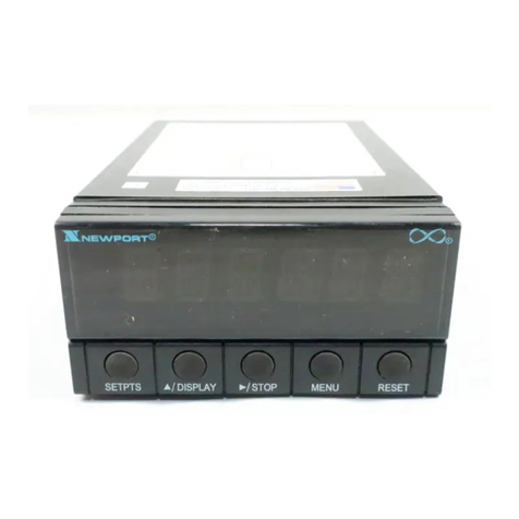
Newport Electronics INFINITY MICRO-INFINITY ICN77000 Series User manual

Counters
Frequency Meters
PID Controllers
Clock/Ti ers
Printers
Process Meters
On/Off Controllers
Recorders
Relative Hu idity
Trans itters
Ther ocouples
Ther istors
Wire
Rate Meters
Ti ers
Totalizers
Strain Gauge Meters
Volt eters
Multi eters
Soldering Iron Testers
pH Pens
pH Controllers
pH Electrodes
RTDs
Ther owells
Flow Sensors
NEWPORT Electronics, Inc.
®
Additional Products fro
THE NEW STANDARD FOR QUALITY
It is the policy of NEWPORT to co ply with all worldwide safety and EMC/EMI regulations that apply. NEWPORT is constantly pursuing certification of its products to the
European New Approach Directives. NEWPORT will add the CE ark to every appropriate device upon certification.
The infor ation contained in this docu ent is believed to be correct but NEWPORT Electronics, Inc. accepts no liability for any errors it contains, and reserves the right to
alter specifications without notice.
WARNING: These products are not designed for use in, and should not be used for, patient connected applications.
TRADEMARK NOTICE:
a
®
,,, newportUS.com, , , , , and
the “Meter Case Bezel
Design”
are trade arks of NEWPORT Electronics, Inc.
PATENT NOTICE: The “Meter Case Bezel Design” is a trade ark of NEWPORT Electronics, Inc., registered in the U.S. This product is covered by one or ore of the following
patents: U.S. Pat. No. D336,895; 5,274,577/ FRANCE BREVET No. 91 12756/ UK PATENT No. GB2 248 954; GB2 249 837/ SPAIN 2039150; 2048066/ ITALY 1249456;
1250938/ CANADA 2052599; 2052600/ GERMANY DE 4134398 C2. OTHER U.S. AND INTERNATIONAL PATENTS PENDING OR APPLIED FOR.
NEWPORT
®
NEWPORT
®
This device is arked with the international caution sy bol. It is i portant to read the Setup Guide before installing or co issioning this device as it contains i portant
infor ation relating to safety and EMC.
For Immedi te Assist nce
In the U.S.A. nd C n d : 1-800-NEWPORT
®
In Mexico: (95) 800-NEWPORT
SM
Or c ll your loc l NEWPORT Office.
Internet e-m il
NEWPORTnetSM On-Line Service
www.newportUS.co
Downloaded from Elcodis.com electronic components distributor

To Order Model ICN77000 SERIES CONTROLLER (Specify Model Number)
PROCESS CONTROLLER, DUAL DISPLAY FOR THERMOCOUPLE, RTD, VOLTAGE OR CURRENT INPUTS IN A 1/16 DIN CASE
Ordering Ex mples:
1.) ICN77R322-C2 is a NEMA 1 bezel case with 1.75 inch round hole ounting adaptor, dual SSR control outputs and RS232 co unications output.
2.) ICN77330 is a NEMA 12 bezel case with 1/16 DIN ounting and single Relay control output.
3.) ICN77544-A2 is a NEMA 4 bezel case with 1/16 DIN ounting, dual pulse control outputs, and a SPST 3A Alar relay.
Model No. Description
ICN77 Dual displays for si ultaneous display of easured value and setpoint.
Selectable preset tune, adaptive tune, autotune, PID, PI, PD control odes. The
dual control outputs can be configured for a variety of control and alar
applications such as heat, heat/cool, heat/alar , cool or cool/alar . The ra p to
setpoint feature allows the user to define the rate of rise to setpoint, ini izing
ther al shock to the load during start-up. Maxi u ra p ti e 99.59 (HH.MM),
Soak: 00.00 to 99.59 (HH.MM),Da ping: 1 to 8 in unit steps. Input types
J,K,T,E,R,S,B,N,J-DIN°C, RTD 100Ω 0.00385, 100Ω & 1kΩ 0.00392, 0 to 20 A,
4 to 20 A, 0 to 100 V, 0 to 1V, 0 to 10Vdc. Alar 1 output includes SPST relay,
3A @ 120Vac, 3A @ 240Vac.
NOTE: The Controller ust be ordered co pletely configured. Options are not field installable.
[ ] CASE TYPE
R3 NEMA 1, 1.89 x1.89" (48 x 48 ) bezel and 1.75" ROUND cutout
R5 NEMA 1, 2.1 x 2.1" bezel and 1.75” ROUND cutout
3 NEMA 12 bezel for
1
/
16
DIN panel cutout 45 x 45 (1.772 x 1.772")
5 NEMA 4 bezel for
1
/
16
DIN panel cutout 45 x 45 (1.772 x 1.772")
[ ] CONTROL OUTPUT #1 (Direct or Reverse Acting)
2 Solid State Relay SSR : 1A @ 120/240Vac continuous
3 Relay: For “C” 5A @ 120Vac, 3A @ 240Vac
4 Pulsed 10Vdc @20 A (for use with external SSR)
5 Non-Isolated 1 to 10Vdc or 0-20 A @500Ω ax
[ ] CONTROL OUTPUT #2 (Direct or Reverse Acting)
0 Insert “0” if second output is not desired
2 Solid State Relay SSR: 1A @ 120/240Vac continuous
3 Relay: For “C” 5A @ 120Vac, 3A @ 240Vac
4 Pulsed 10Vdc @20 A (use for external SSR)
Model No. Description cont.
[ ] OPTIONAL OUTPUTS
*none (no entry required)
-A2 SPST relay, 3A@ 120Vac, 3A @ 240Vac (Alar 2)
-C2 Isolated RS232, 300 to 19.2k baud
-C4 Isolated RS485, 300 to 19.2k baud
-PV Isolated Analog Output
-RSP Re ote Setpoint Selection
[ ] POWER SUPPLY
*90 to 240 Vac/dc, 50 to 400Hz (no entry required)
NEMA 1/UL Type 1: Intended for indoor use, to provide a degree of
protection against contact with the enclosed equip ent and against li ited
a ount of falling dirt.
NEMA 4/UL Type 4: Intended for indoor use, to provide a degree of
protection against splashing water, windblown dust and rain, and hose
directed water and unda aged by the for ulation of ice on the enclosure.
Testing-Hosedown:Enclosure is subjected to a strea of water fro a
hose which has a 1" dia eter nozzle and which delivers at least 65 gallons
per inute fro a distance of 10 to 12 feet for a ini u of 5 inutes.
NEMA 12/UL Type 12: Intended for indoor use, to provide a degree of
protection against circulating dust, falling dirt, and dripping non-corrosive
liquids. Testing-Drip:Enclosure is subjected to a drip pan which produces
both splashing and dripping. Testing-Atomized ater:Enclosure is
subjected to a spray of ato ized water by using a nozzle that produces a
3" round dia eter spray, 12" fro enclosure. The air pressure is at 30psi.
For harsh environ ents, we reco end installation of the controller for
square panel cutouts.
Downloaded from Elcodis.com electronic components distributor

P rt 1: Introduction
1.1 S fety Consider tions .........................................................................1
1.2 Before You Begin..................................................................................2
P rt 2: Setup
2.1 Mounting the Controller.......................................................................4
2.2 Front P nel View ..................................................................................7
Front Panel Annunciators.......................................................................7
2.3 Re r P nel View....................................................................................8
Rear Panel Connector Labels ................................................................9
2.4 Mech nic l Inst ll tion ......................................................................10
Dip Switch Configuration ......................................................................10
Dip Switch Settings...............................................................................11
2.5 Electric l Inst ll tion .........................................................................12
Input Connection Examples .................................................................13
2.5.1 Ther ocouple.......................................................................................13
2.5.2 Two/Three/Four Wire RTD ...................................................................14
2.5.3 Process Current ...................................................................................15
2.5.4 Process Voltage ...................................................................................15
T
ABLE OF
C
ONTENTS
i
Downloaded from Elcodis.com electronic components distributor

P rt 3: Oper tion: Configur tion Mode
3.1 Introduction........................................................................................16
Turning Your Controller on for the First Time .............................................16
Function in Configuration Mode................................................................17
3.2 Menu Configur tion...........................................................................18
ID Number .............................................................................................19
Set Points ..............................................................................................20
Input Type (Thermocouple) ......................................................................24
Input Type (RTD) ....................................................................................25
Input Type (RTD Value)...........................................................................26
Input Type (Process) ...............................................................................27
Reading Configuration.............................................................................29
Alarm 1..................................................................................................33
Alarm 2..................................................................................................36
Loop Break Alarm...................................................................................38
Output 1 ................................................................................................42
Output 2 ................................................................................................52
Ramp & Soak.........................................................................................58
3.3 Av il ble Options...............................................................................60
Analog Output Option..............................................................................61
Communication Option............................................................................64
T
ABLE OF
C
ONTENTS
ii
Downloaded from Elcodis.com electronic components distributor

T
ABLE OF
C
ONTENTS
iii
Configur tion Mode Cont.
Command Formats ...........................................................................................................72
Reading Scale .............................................................................................................................86
Reading Offset .................................................................................................................87
Remote Setpoint Option ....................................................................................................88
P rt 4 Specifc tions
.........................................................................................91
List of Figures
Figure 2.1 a. — Mounting the Square Mount Controller .................................................................5
Figure 2.1 b. — Mounting the Round Mount Controller ..................................................................6
Figure 2.2 — Front Panel Display ...................................................................................................7
Figure 2.3 — Typical Rear Connector Label and Possible Labels of Different Models ..................8
Figure 2.4 — Dip Switch Location.................................................................................................10
Figure 2.5.1 — Power Wiring Hookup...........................................................................................12
Figure 2.5.2 — Ther ocouple Wiring Hookup..............................................................................13
Figure 2.5.3 — Two-wire RTD Hookup, Three-Wire RTD Hookup, Four -Wire RTD Hookup ......14
Figure 2.5.4 — Process Current Wiring Hookup...........................................................................15
Figure 2.5.5 — Process Voltage Wiring Hookup...........................................................................15
Figure 3.1 — Flowchart for ID and Set Point Menus ....................................................................18
Figure 3.2 — Flowchart for Input Type..........................................................................................23
Figure 3.3 — Flowchart for Reading Configuration.......................................................................28
Downloaded from Elcodis.com electronic components distributor

List of Figures Cont.
Figure 3.4 — Flowchart for Alar 1 and Alar 2..........................................................................32
Figure 3.5 — Flowchart for Loop Break ........................................................................................37
Figure 3.6 — Flowchart for Output 1.............................................................................................41
Figure 3.7 — Flowchart for Output 2.............................................................................................51
Figure 3.8 — Flowchart for Ra p & Soak ....................................................................................57
Figure 3.9 — Flowchart for Analog Output Option ........................................................................61
Figure 3.10 — Flowchart for Co unication Option....................................................................64
Figure 3.11 — Flowchart for Re ote Setpoint..............................................................................88
List of T bles
Table 3.1 — Co unication Co ands..................................................................................... 72
Table 3.2 — Co and Letters and Index .................................................................................. 76
T
ABLE OF
C
ONTENTS
iv
Downloaded from Elcodis.com electronic components distributor

1.1 S fety Consider tions
This device is arked with the international caution sy bol. It is
i portant to read this anual before installing or co issioning
this device as it contains i portant infor ation relating to Safety
and EMC (Electro agnetic Co patibility).
This instru ent is a panel ount device protected in
accordance with Class I of EN 61010 (115/230 AC power
connections). Installation of this instru ent should be done by
qualified personnel. In order to ensure safe operation, the
following instructions should be followed.
This instru ent has no power-on switch. An external switch or
circuit-breaker shall be included in the building installation as a
disconnecting device. It shall be arked to indicate this
function, and it shall be in close proxi ity to the equip ent
within easy reach of the operator. The switch or circuit-breaker
shall eet the relevant require ents of IEC 947–1 and IEC
947-3 (International Electrotechnical Co ission). The switch
shall not be incorporated in the ain supply cord.
Further ore, to provide protection against excessive energy
being drawn fro the ain supply in case of a fault in the
equip ent, an overcurrent protection device shall be installed.
• Do not exceed voltage rating on the label located on the
top of the instru ent housing.
• Always disconnect power before changing signal and
power connections.
• Do not use this instru ent on a work bench without its
case for safety reasons.
• Do not operate this instru ent in fla able or explosive
at ospheres.
• Do not expose this instru ent to rain or oisture.
• Unit ounting should allow for adequate ventilation to
ensure instru ent does not exceed operating te perature
rating.
• Use electrical wires with adequate size to handle
echanical strain and power require ents. Install without
exposing bare wire outside the connector to ini ize
electrical shock hazards.
EMC Consider tions
• Whenever EMC is an issue, always use shielded cables.
• Never run signal and power wires in the sa e conduit.
• Use signal wire connections with twisted-pair cables.
• Install Ferrite Bead(s) on signal wires close to the
instru ent if EMC proble s persist.
F ilure to follow ll instructions nd w rnings m y result in injury!
I
NTRODUCTION
part
1
1
Downloaded from Elcodis.com electronic components distributor

part
1
I
NTRODUCTION
2
1.2 Before You Begin
If you need assistance, please contact the nearest Custo er Service Depart ent,
listed in this anual.
Re ove the packing slip and verify that you have received everything listed.
Inspect the container and equip ent for signs of da age as soon as you receive
the ship ent. Note any evidence of rough handling in transit. I ediately report
any da age to the shipping agent. The carrier will not honor da age clai s
unless all shipping aterial is saved for inspection. After exa ining and re oving
the contents, save the packing aterial and carton in the event reship ent is
necessary.
The latest Operation and Co unication Manual as well as free configuration
software are available fro the website listed in this m nu l or on the CD-ROM
enclosed with your shipment.
For first-ti e users: Refer to the QuickStart Manual for basic operation and set-up
instructions.
If you have the Serial Co unications Option you can easily configure the
controller on your co puter or on-line.
Manuals, Software:
nspecting Your Shipment
Customer Service
Downloaded from Elcodis.com electronic components distributor

I
NTRODUCTION
part
1
3
TO DISABLE OUTPUTS
Standby ode is useful during setup of the controller or when aintenance of the
syste is necessary. When the controller is in standby, it re ains in the ready
condition but all outputs are disabled. This allows the syste to re ain powered and
ready to go.
PUSH ENTER TWICE to disable the syste during an EMERGENCY.
When the controller is in "RUN" Mode, push ENTER
twice to dis ble ll outputs nd l rms.
It is now in "STANDBY" Mode. Push ENTER once
ore to resu e "RUN" Mode.
Downloaded from Elcodis.com electronic components distributor

part
2
S
ETUP
6
Round Mount Micro Controller Mounting Instructions
1. Separate the display fro the eter by squeezing the case (where shown) and then
unplugging the cable fro the eter.
2. Slide the retainer over the rear of the case, but do not engage serrations on
case.
3. Pass the cable (fro the display) thru a 1 3/4"dia eter hole in the ounting
panel and connect to the eter (take care to center the
connector on the ating pins). While squeezing the case,
press the display and eter squarely together
until they connect.
4. Check the display and gasket for proper
align ent, then slide the retainer tight against
the backside of the ounting panel.
Figure 2.1b — Mounting the Round Mount Controller
Round Mount
Downloaded from Elcodis.com electronic components distributor

S
ETUP
part
2
Fro t Pa el A u ciators
SP1 OUT1/Setpoint 1 indicator.
SP2 OUT2/Setpoint 2 indicator.
AL1 Alar 1 indicator.
AL2 Alar 2 indicator.
°C °C unit indicator.
°F °F unit indicator.
PV Upper display shows the Process Value
SV Lower display shows the Setpoint Value
MENU Changes display to Configuration Mode and advances thru enu ite s*
/MAX Used in progra ode and peak recall*
/MIN Used in progra ode and valley recall*
ENTER Accesses sub enus in Configuration Mode and stores selected values*
* See Part 3 Operation:Configuration Mode
Figure 2.2 Front Panel Display
2.2. Front P nel View
7
Downloaded from Elcodis.com electronic components distributor

S
ETUP
part
2
9
Rear Pa el Co ector Labels
POWER AC Power Connector: All odels
INPUT Input Connector: All odels
TC, PR (Process)
RTD
ALARM 1 ALARM 1 relay SPST, progra able: All odels
OUTPUT 1 Control Output 1: Based on one of the following odels.
Relay SPDT Voltage and Current
Solid State Relay Pulse
OUTPUT 2 Control Output 2: Based on one of the following odels:
Relay SPST Nor ally Open
Solid State Relay
Pulse
OPTION Based on one of the following odels:
RS-232C Isolated Analog Out
RS-485 Alar 2 Relay SPST, progra able
Re ote Setpoint
Downloaded from Elcodis.com electronic components distributor

part
2
S
ETUP
10
2.4. Mech nic l Inst ll tion
The settings of the DIP switch must be verified or set to comply with your
selection t the Input/Type menu (see Section 3.0 for Input/Type). The DIP
switch is accessible through an opening on the side of the case or ay be accessed
by re oving the controller fro the case, see Section 2.1 for instructions. Locate the
dip switch (see Figure 2.4) and set the switches according to the following tables.
Figure 2.4 Dip Switch Location — switch settings are shown in OFF position
Dip Switch
Configuration
opening in case
Unit installed in case. Unit re oved fro case.
Downloaded from Elcodis.com electronic components distributor

part
2
S
ETUP
12
2.5. Electric l Inst ll tion
POWER CONNECT ON EXAMPLES
The figure below shows the power wiring hookup.
Fuse Connector Output Type 115 V c 230 V c
Fuse 1 Output 1 Relay 5 A(T) 3 A(T)
Fuse 2 Output 1 Relay 5 A(T) 3 A(T)
SSR 0.5 A(T) 0.5 A(T)
Fuse P Power N/A 100 A(T) 100 A(T)
Fuse A Alar 1/2 Relay 3 A(T) 3 A(T)
Note: Values shown are ini u reco endations for the
protection of the controller. For a specific load, consult the respected
electrical specifications to select a suitable fuse.
The Protective Conductor termin l must be
connected for s fety re sons.
The Safety European Standard EN61010-1 for easure ent, control, and laboratory
equip ent requires that fuses ust be specified based on IEC127. This standard
specifies for a Ti e-lag fuse, the letter code “T”. The above reco ended fuses are
of the type IEC127-2-sheet III. Be aware that there are significant differences
between the require ents listed in the UL 248-14/CSA 248.14 and the IEC 127 fuse
standards. As a result, no single fuse can carry all approval listings. A 1.0 A p IEC
fuse is approxi ately equivalent to a 1.4 A p UL/CSA fuse. It is advised to consult
the anufacturer’s data sheets for a cross-reference.
Use copper conductors only for power
connections
Figure 2.5.1 Power Wiring Hookup
Note ☞
For SSR wiring hook-up exa ples, refer to Specification Section.
Downloaded from Elcodis.com electronic components distributor
Table of contents
Other Newport Electronics Controllers manuals
Popular Controllers manuals by other brands
Carel
Carel ir33+ FMC quick guide
YASKAWA
YASKAWA Motoman DX200 instructions

Becker
Becker Centronic UnitControl UCS520 operating instructions
omal automation
omal automation Rackon RK10 instruction manual
TJERNLUND
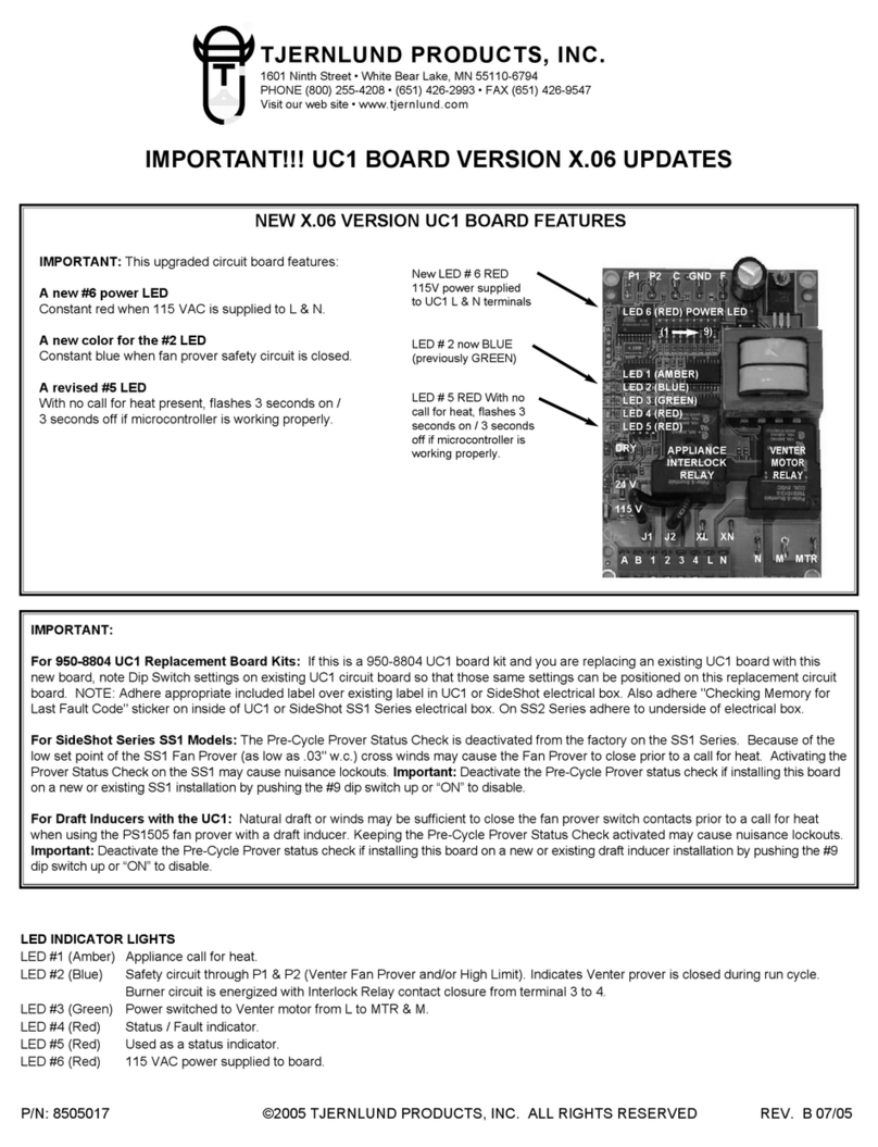
TJERNLUND 950-8804 UC1 UNIVERSAL CONTROL BOARD KIT (VERSION X.04) 8505017 REV A... manual
Gemini
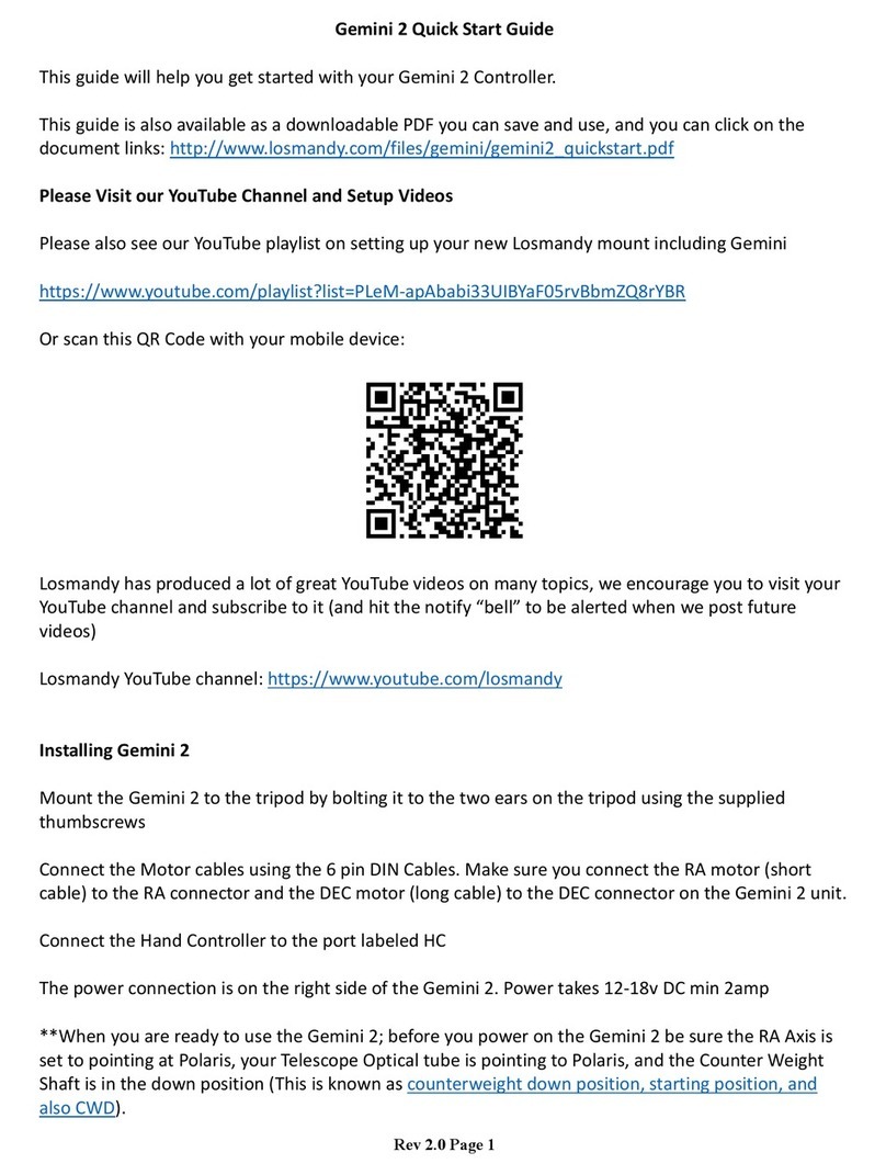
Gemini 2 quick start guide


