Newport Electronics 305-RTD User manual

305-RTD
Miniature Panel Thermometer
11434ML-02A
Made in the USA
This device is marked with the international caution symbol. It is important
to read the Setup Guide before installing or commissioning this device as it
contains important information relating to safety and EMC.
It is the policy of NEWPORT to comply with all worldwide safety and EMC/EMI
regulations that apply. NEWPORT is constantly pursuing certification of its
products to the European New Approach Directives. NEWPORT will add the CE
mark to every appropriate device upon certification.
© Copyright 1998, NEWPORT Electronics, Inc. All rights reserved.
This documentation may not be copied, photocopied, reproduced, translated, or
reduced to any electronic medium or machine-readable form, in whole or in part,
without prior written consent of NEWPORT Electronics, Inc.

TABLE OF CONTENTS
SECTION PAGE
Preface . . . . . . . . . . . . . . . . . . . . . . . . . . . . . . . .ii
Models Available . . . . . . . . . . . . . . . . . . . . . . . . .iii
Section 1 Introduction . . . . . . . . . . . . . . . . . . . . . . . . . . . . .1
1.1 Unpacking . . . . . . . . . . . . . . . . . . . . . . . . . . . . .1
1.2 Safety Considerations . . . . . . . . . . . . . . . . . . . . .2
Section 2 About the Meter . . . . . . . . . . . . . . . . . . . . . . . . .3
2.1 Front of the Meter . . . . . . . . . . . . . . . . . . . . . . . .3
2.2 Back of the Meter . . . . . . . . . . . . . . . . . . . . . . . .4
2.3 Connector Description . . . . . . . . . . . . . . . . . . . . .4
Section 3 Getting Started . . . . . . . . . . . . . . . . . . . . . . . . . .5
3.1 Main Board Power Jumpers . . . . . . . . . . . . . . . .5
3.2 Changing the Meter Parameters . . . . . . . . . . . . .7
3.3 Installation and Panel Mounting . . . . . . . . . . . . .10
3.4 Sensor Input Connections . . . . . . . . . . . . . . . . .12
3.5 Analog Output Connections . . . . . . . . . . . . . . . .14
3.6 Display Hold Connections . . . . . . . . . . . . . . . . .15
3.7 Main Power Connections . . . . . . . . . . . . . . . . .16
3.8 Disassembly/Assembly . . . . . . . . . . . . . . . . . . .18
Section 4 Operation and Calibration . . . . . . . . . . . . . . . . .20
4.1 Equipment Required . . . . . . . . . . . . . . . . . . . . .20
4.2 Calibration Procedure . . . . . . . . . . . . . . . . . . . .21
Section 5 Specifications . . . . . . . . . . . . . . . . . . . . . . . . . .23
Section 6 Glossary . . . . . . . . . . . . . . . . . . . . . . . . . . . . . .26
i

ii
PREFACE
Manual Objectives: This manual shows you how to set up and
use the RTD Panel Thermometer.
This meter is an economical Miniature Temperature Panel
Thermometer featuring a large display with a linearized analog
output that is supplied as a standard feature.
Each of the models* can be converted by the user to display in
degrees Fahrenheit or Celsius between one degree and a tenth
degree resolution.
RTD is an abbreviation for resistive temperature detector. The
meter is designed to measure 100 ohm platinum resistance with
0.00385 temperature coefficient, also known as the European
curve. The RTD will change resistance with a change in
temperature. When using a 2-wire measurement configuration,
lead wire impedance can contribute significant error to the
temperature measurement. When using long lead wires a 3- or
4-wire measurement configuration is recommended.
The meter is available in platinum RTD with 2-, 3-, or 4-wire
connections. All of the models listed in Table 1-1 come standard
with red LEDs, and can be ordered with a green LED display as
an option. The part numbers would then end with Ò-GR".
Also, these meters can be ordered with different power
configurations. Refer to Table 1-3 for available choices.
*Refer to Table 1-1 for the complete listing of models available.
Ê iii
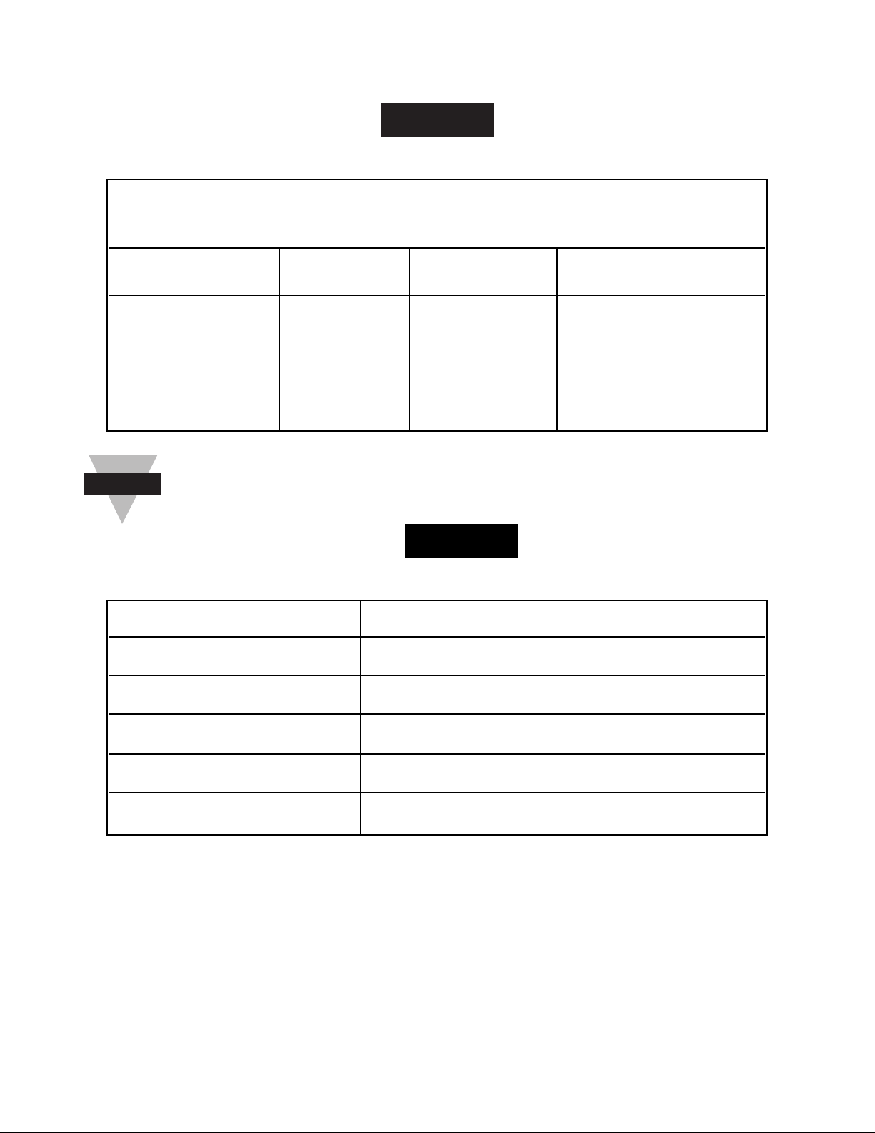
MODELS AVAILABLE
TABLE 1-1
RTD MODELS AVAILABLE
The accuracies and ranges are listed in Section 5.
TABLE 1-2
Power Options Available
MODEL POWER
305-Mxx-C0 115 Vac ±15%, 50/60 Hz
305-Mxx-C1 230 Vac ±15%, 50/60 Hz
305-Mxx-C2A 9-26 Vdc @ 110mA max.
305-Mxx-C5 100 Vac ±15%, 50/60 Hz
305-Mxx-C8 24 Vac ±15%, 50/60 Hz
Note
☞
The following 3-1/2 digit mini RTD panel meters are
available and discussed in this OperatorÕs Manual.
MODEL TYPE ¡C or ¡F RESOLUTION
305-MF1 RTD F 1.0¡F
305-MF2 RTD F 0.1¡F
305-MC1 RTD C 1.0¡C
305-MC2 RTD C 0.1¡C

Êiv
TABLE 1-3
Other Models Available
The following 3-1/2 digit mini thermocouple panel
thermometers are discussed in a separate manual.
MODEL TYPE ¡C or ¡F RESOLUTION
305-JF1 J F 1.0¡F
305-
JF2 J F 0.1¡F
305-
JC1 J C 1.0¡C
305-
JC2 J C 0.1¡C
305-KF1 K F 1.0¡F
305-KF2 K F 0.1¡F
305-KC1 K C 1.0¡C
305-KC2 K C 0.1¡C
305-TF1 T F 1.0¡F
305-TF2 T F 0.1¡F
305-TC1 T C 1.0¡C
305-TC2 T C 0.1¡C
305-EF1 E F 1.0¡F
305-EF2 E F 0.1¡F
305-EC1 E C 1.0¡C
305-EC2 E C 0.1¡C
Êv
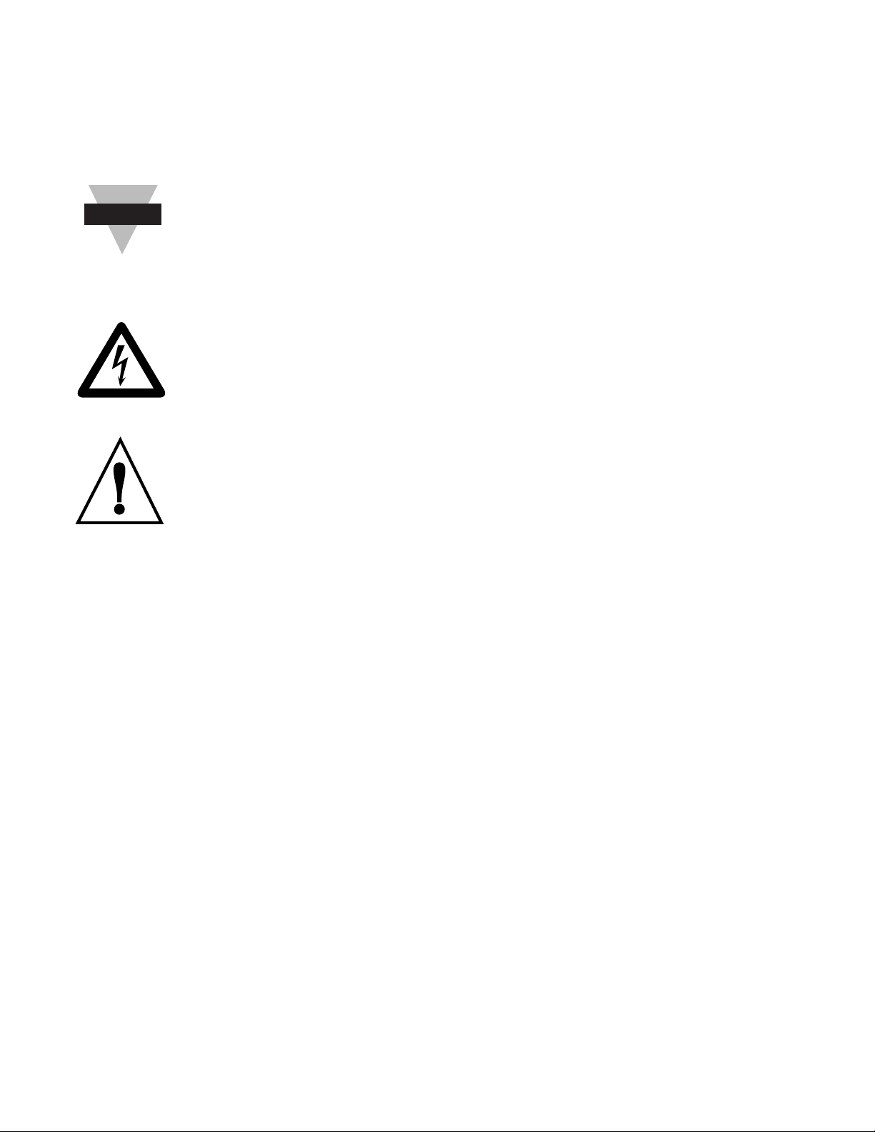
NOTES, WARNINGS and CAUTIONS
Information that is especially important to note is identified by
these labels:
NOTE: provides you with information that is important
to successfully setup and use the Programmable
Digital Meter.
CAUTION or WARNING: tells you about the risk of
electric shock.
CAUTION, WARNING or IMPORTANT: tells you of
circumstances or practices that can effect the meter's
functionality and must refer to accompanying
documents.
Note
☞

1
SECTION 1 INTRODUCTION
1.1 UNPACKING
Remove the Packing List and verify that all equipment has been
received. If there are any questions about the shipment, use the
phone number for the Customer Service Department nearest
you.
Upon receipt of shipment, inspect the container and equipment
for any signs of damage. Take particular note of any evidence of
rough handling in transit. Immediately report any damage to the
shipping agent.
The carrier will not honor any claims unless all shipping
material is saved for their examination. After examining
and removing contents, save packing material and
carton in the event reshipment is necessary.
Verify that you received the following items in the shipping box:
QTY DESCRIPTION
1 Panel Thermometer with 3 small connectors plugged
into the rear of the meter.
1 OperatorÕs Manual
Note
☞

2
1.2 SAFETY CONSIDERATIONS
This device is marked with the international caution symbol. It is important to read this
manual before installing or commissioning this device as it contains important
information relating to Safety and EMC (Electromagnetic Compatibility).
Unpacking & Inspection
Unpack the instrument and inspect for obvious shipping damage. Do not attempt to
operate the unit if damage is found.
This instrument is a panel mount device protected in accordance with Class I of EN
61010 (115/230 AC power connections). Installation of this instrument should be done
by Qualified personnel. In order to ensure safe operation, the following instructions
should be followed.
This instrument has no power-on switch. An external switch or circuit-breaker shall be included in
the building installation as a disconnecting device. It shall be marked to indicate this function, and
it shall be in close proximity to the equipment within easy reach of the operator. The switch or
circuit-breaker shall not interrupt the Protective Conductor (Earth wire), and it shall meet the relevant
requirements of IEC 947–1 and IEC 947-3 (International Electrotechnical Commission). The switch
shall not be incorporated in the mains supply cord.
Furthermore, to provide protection against excessive energy being drawn from the mains supply in
case of a fault in the equipment, an overcurrent protection device shall be installed.
• The Protective Conductor must be connected for safety reasons. Check that the power
cable has the proper Earth wire, and it is properly connected. It is not safe to operate
this unit without the Protective Conductor Terminal connected.
• Do not exceed voltage rating on the label located on the top of the instrument housing.
• Always disconnect power before changing signal and power connections.
• Do not use this instrument on a work bench without its case for safety reasons.
• Do not operate this instrument in flammable or explosive atmospheres.
• Do not expose this instrument to rain or moisture.
• Unit mounting should allow for adequate ventilation to ensure instrument does not
exceed operating temperature rating.
• Use electrical wires with adequate size to handle mechanical strain and power
requirements. Install without exposing bare wire outside the connector to minimize
electrical shock hazards.
EMC Considerations
• Whenever EMC is an issue, always use shielded cables.
• Never run signal and power wires in the same conduit.
• Use signal wire connections with twisted-pair cables.
• Install Ferrite Bead(s) on signal wires close to the instrument if EMC problems
persist.
Note
☞
Note
☞
3
SECTION 2 ABOUT THE METER
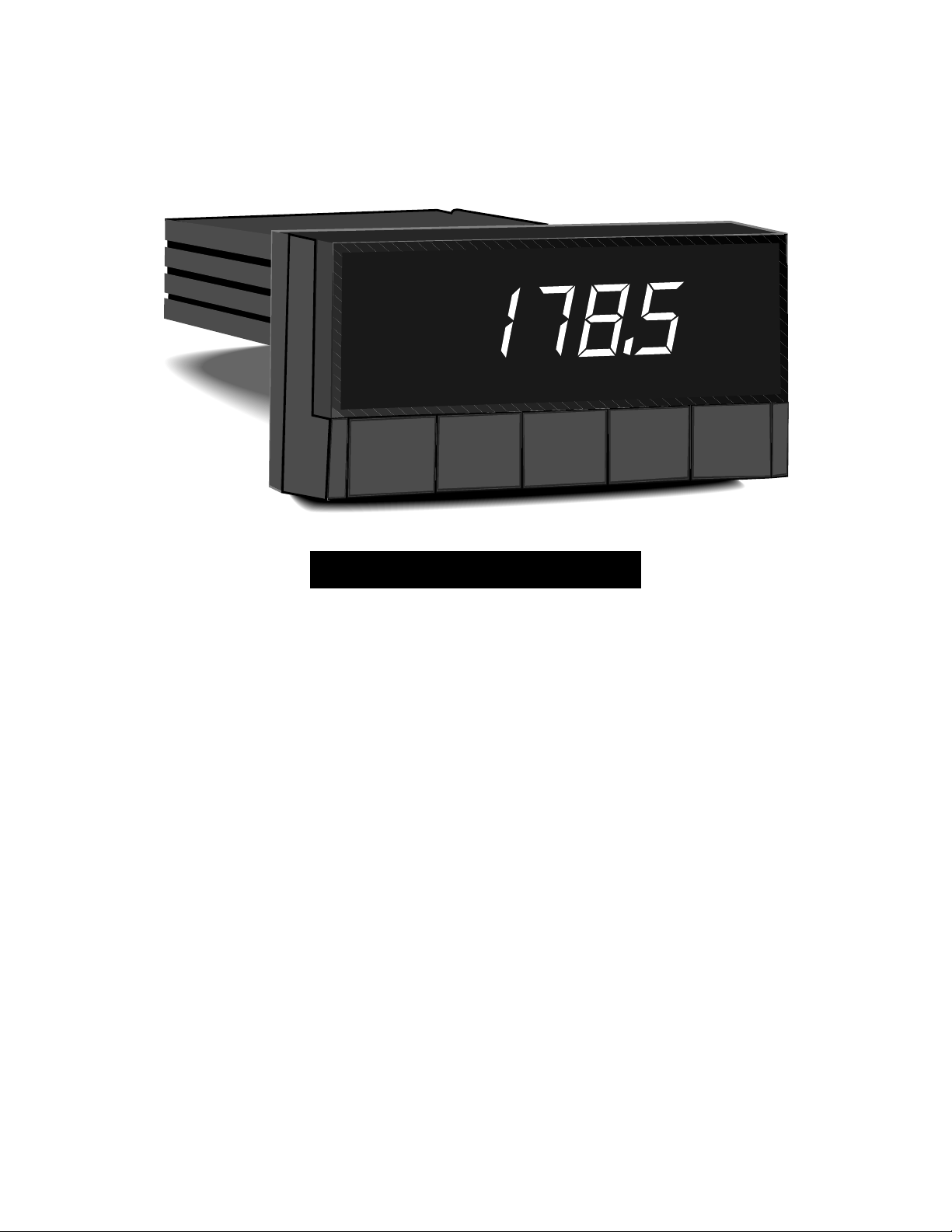
2.1 Front of the Meter
Figure 2-1 shows the panel thermometer.
Figure 2-1. Panel Thermometer
Features:
Display:3 1/2 Digit, 7-Segment Red or Green LED
Full-size:14.2 mm (0.56") LED Display
Analog Output Standard
1/8 DIN Standard Panel Cutout
Removable Screw-Clamp Cable Connector
Display Hold Capability
4
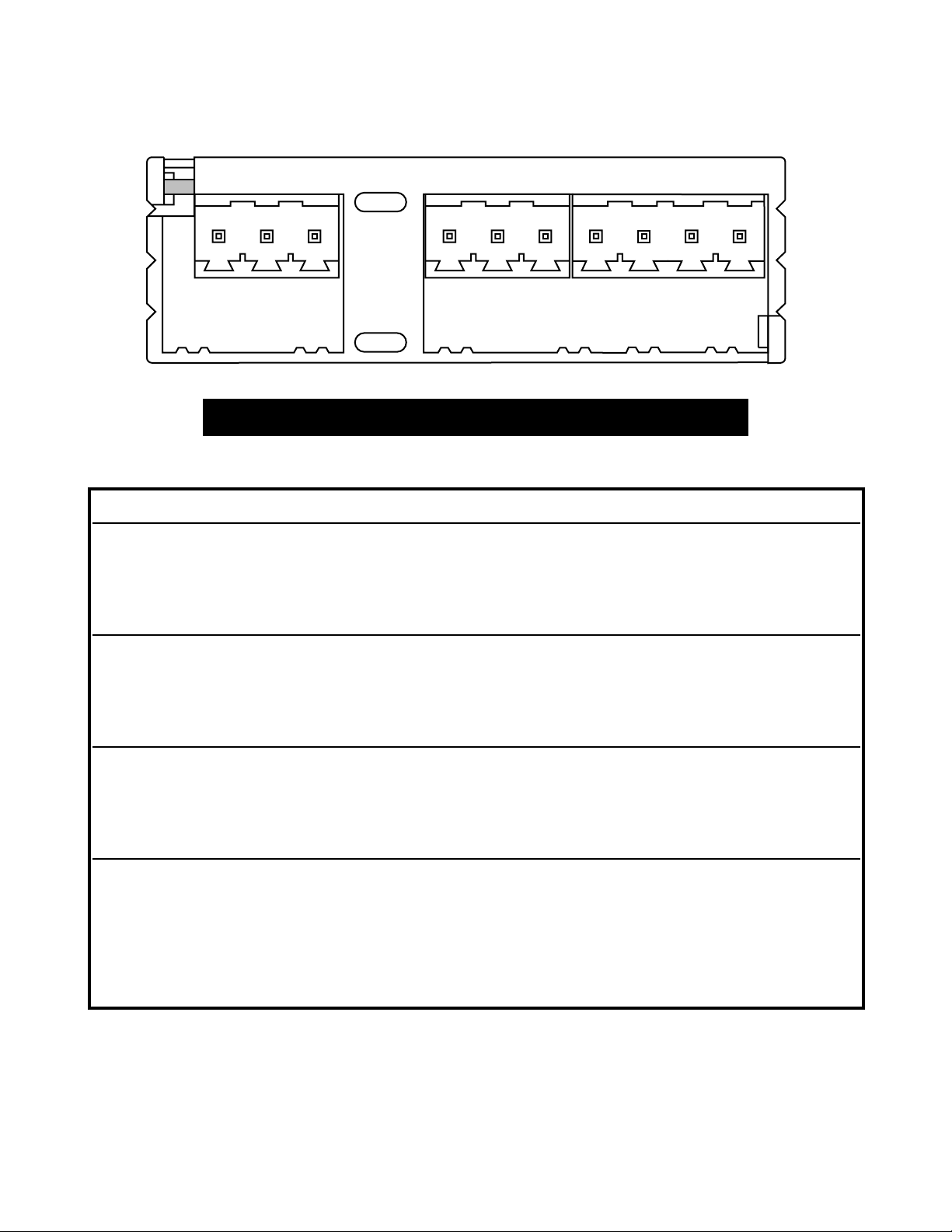
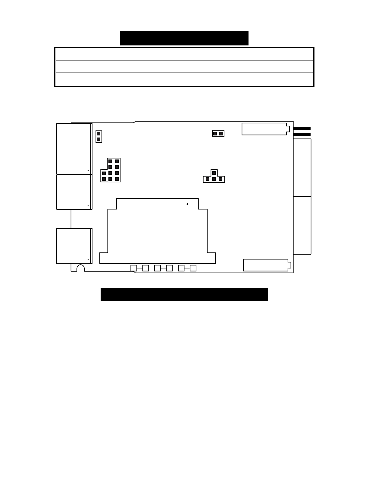
2.2 Back of the Meter
Figure 2-2 illustrates the rear of the meter.
Figure 2-2. Rear View Showing P1, P2, P3 Locations
2.3 Connector Description
For RTD input wires, refer to Figure 3-3 thru 3-6.
Connector Description Connector PIN #
(AC) Earth Ground P1 1
(AC) Neutral P1 2
(AC) Line P1 3
(DC) -DC Return P1 1
(DC) +DC P1 2
(DC) No Connection (Not used) P1 3
Display Hold (Active Low) P2 1
Analog Return P2 2
Analog Output P2 3
RTD Input -EXC P3 1
RTD Input Signal Lo P3 2
RTD Input Signal Hi P3 3
RTD Input +EXC P3 4
P1 P2 P3
123 123 3412

5
SECTION 3 GETTING STARTED
3.1 Main Board Power Jumpers
Caution: The meter has no power-on switch, so it will
be in operation as soon you apply power.
The meter can be configured to operate on 115VAC or
230VAC by the proper combination of the soldered wire
jumpers that are located on the printed circuit board.
The meter is set at the factory to be powered by the
voltage specified at the time of ordering. The same
transformer is used for either configuration, so all you
need to do is to select the jumpers as described in this
section.
Important: These changes must be performed by a
qualified technician.
To change the Factory preset jumpers, do the following
steps:
Disconnect the power from the unit before proceeding.
1. Remove the main board from the case. Refer to
Disassembly/Assembly Section 3.8.
2. Locate the solder jumpers W1, W2, and W3 (located
near the edge of the main board alongside the
transformer).
3. If your power requirement is 115 V ac, solder jumpers
W1 and W3 should be wired, but jumper W2 should
not. If your power requirement is 230 Vac, solder
jumper W2 should be wired, but jumpers W1 and W3
should not.
Note
☞
6
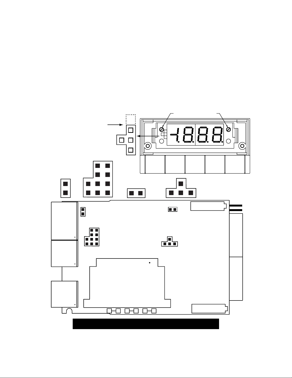
Voltage Jumper Pin Settings
Figure 3-1 shows the location of solder jumpers W1 through W3.
Figure 3-1. Power Jumper Locations
P3
P1
W1 W2 W3
2
1
2
3
1
TRANSFORMER
SPAN
DISPLAY
ZERO
(COMPONENT SIDE)
P2 2
3
1
3
4S2
S3
S4
S5
AC VOLTAGE INSTALL REMOVE
115VAC W1, W3 W2
230VAC W2 W1, W3
7
3.2 Changing the Meter Parameters
The proper combinations of jumper plugs S1, S2, S3, S4, and S5
inside the meter allow you to change various parameters of the
meter. These parameters include resolution, range, units, RTD
sensor configuration and sensor break configuration. You can
change the parameters by moving the plugs on one or several of
the jumper locations. Keep in mind that the meter is factory set
for 3-wire RTD, and for the upscale position.
Figure 3-2 shows the location of the jumper plugs S1 through S5.
Figure 3-2. Jumper Plugs S1 through S5
P3
P1
W1 W2 W3
2
1
2
3
1
TRANSFORMER
SPAN
DISPLAY
ZERO
(COMPONENT SIDE)
P2 2
3
1
3
4S2
S2 S3
S1
A
AAAC
B
B
CD
E
F
GIH S4 S5
S3
S4
S5
A
C
B
UNUSED PLUG POSITION
S1
ZERO SPAN
8
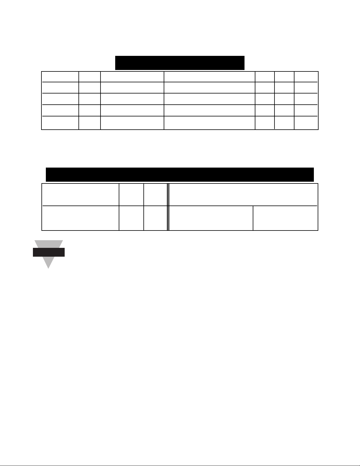
The following tables summarizes what parameters you can
change.
TABLE 3-1 Range Parameters
* Refer to Table 1-1, for complete models (preface section).
TABLE 3-2 2-, 3-, 4-Wire, Upscale, Downscale Configuration
3-Wire input connection is standard. For 2- or 4-Wire
remove S2-A and S3-I
Note
☞
Configuration S2 S3 S3
Upscale (Default) Downscale
2- or 4-wire RTD -- -- A, B, E, F C, D, G, H
3-Wire RTD A I A, B, E, F C, D, G, H
Option F/C Resolution Range S1 S4 S5
*-MF1 ¡F 1¡ -328 to + 1562¡F -- A A
*-MF2 ¡F 0.1¡ -199.9 to + 199.9¡F C -- C
*-MC1 ¡C 1¡ -200 to + 850¡C -- A B
*-MC2 ¡C 0.1¡ -199.9 to + 199.9¡C C -- B
9
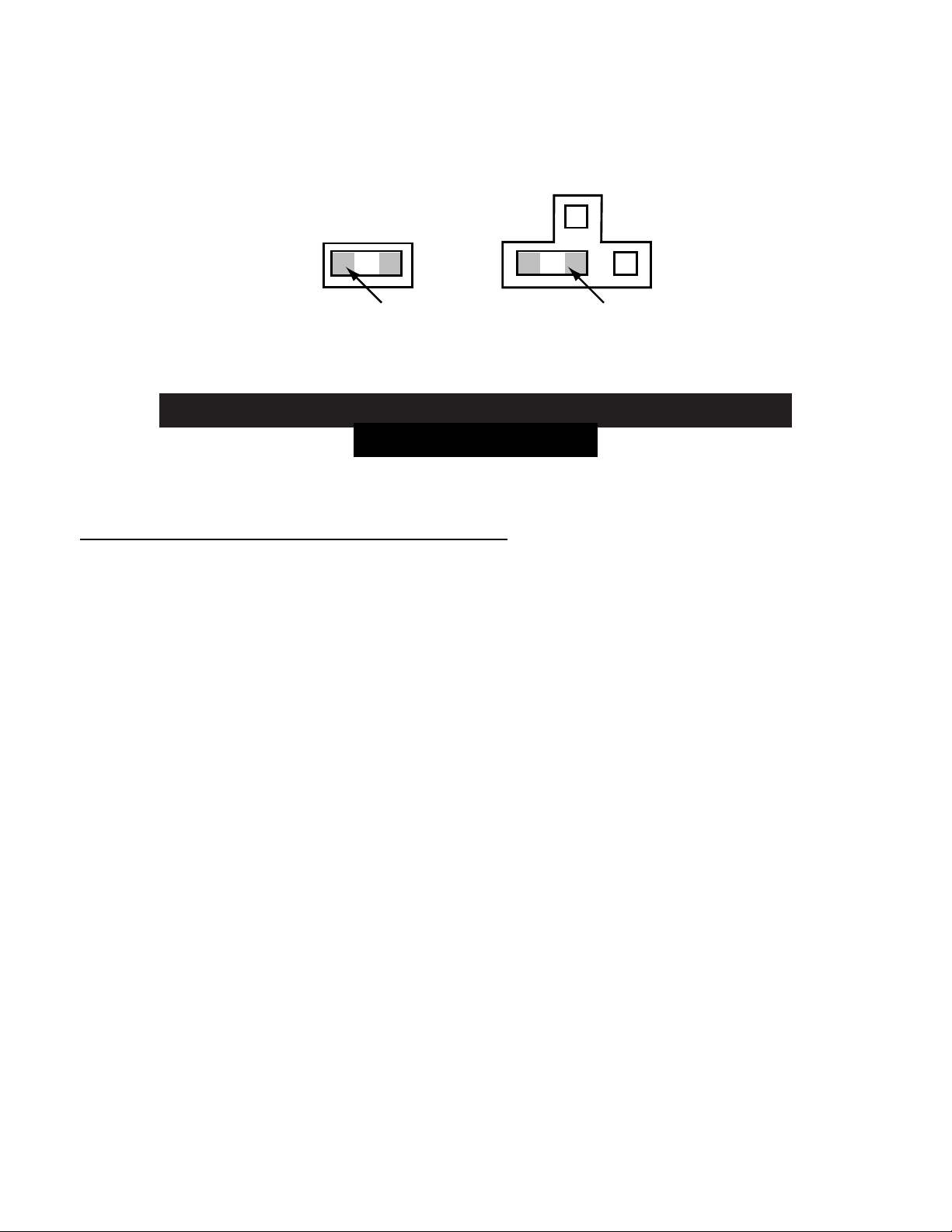
Figure 3-3 gives an example of how to set S4 and S5 to configure
a MF1 meter option. There is a jumper plug across A on S4 and
another jumper plug across A on S5. B and C on S5 are not used.
Figure 3-3. Example of How to Set Meter Option MF1
(jumpers S4 and S5)
SENSOR BREAK PROTECTION:
The proper combination of jumpers on S3 will determine the
direction in which the display and analog output will go if the
RTD sensor breaks (upscale or downscale). The meter is factory
set to upscale break protection. If the sensor breaks, the display
and analog signal will increment (upscale) and the 3 least
significant digits will then go blank. If you require downscale
break protection, refer to Table 3-2 to change the S3 jumper
configuration.
AC
B
S4 S5
JUMPER PLUG
COVERING BOTH PINS JUMPER PLUG
COVERING
TWO PINS
OVER "A"
A

10
Section 3.3 Installation and Panel Mounting
Figure 3-4 shows the panel cutout dimensions, the dimensions
for the panel thickness, and the backplate for mounting the unit
in a panel. Connections will be done after mounting the unit.
1. Remove the 2 phillips screws from behind the display (you
don't have to go inside the meter) holding the rectangular
backplate to the meter. Remove the backplate and set aside.
2. Cut or punch a hole in the panel where you want the meter
to go. The panel can be as thick as 0.25" (6.4mm) to as thin
as 0.03" (0.8mm).
3. Insert the meter into the panel cutout.
4. From the rear of the panel, slide the backplate over the case
(smooth side out).
5. Install the 2 phillips screws to secure the meter in 1/8 DIN
mount. Center the meter in hole prior to tightening screws.

11
Figure 3-4. Installation Information
1/8 DIN PANEL CUTOUT
BACKPLATE
SCREWS
METER
BEZEL
LENS
PANEL WITH
1/8 DIN CUTOUT
0.25 [6.4] MAX
0.03 [0.8] MIN
PANEL THICKNESS
3.622 +0.032/-.000
[92.00 +0.81/-0.00]
1.772 +0.024/-.000
[45.0 +0.61/-0.00]
0.06
[1.5]
4PLCS
R

12
3.4 Sensor Input Connections
The RTD sensor (see Figure 3-5), can be wired in three different
ways. They are 2-, 3-, and 4-wire configurations. The meter is
factory set internally to a 3-wire setup. If you wish to change it,
refer to Table 3-2.
2-Wire RTD:
Externally wire the P3 connector according to Figure 3-6. Keep
in mind that you will need to jumper pins 1 and 2 on P3 together,
and jumper pins 3 and 4 on P3 together. Use 24 AWG wire. The
black lead goes to Pin 1 or 2 and the red lead goes to Pin 3 or 4.
3-Wire RTD:
Externally wire the P3 connector according to Figure 3-7. Pin 4
on the P3 connector is not used.
4-Wire RTD:
Externally wire the P3 connector according to Figure 3-8.
Figure 3-5. RTD P3 Connector
See Figure 2-2 for the location of the P3 connector.
1
2
Screws
underneath
3
4

13
3.4 Sensor Input Connections (Continued)
Figure 3-6. 2-Wire RTD Wiring
Figure 3-7. 3-Wire RTD Wiring
Figure 3-8. 4-Wire RTD Wiring
Refer to Table 3-1 and Table 3-2 for internal jumper
settings.
* Wire colors are for OMEGA RTD wiring only.
Note
☞
METER
4
3
2
1
+ Excitation
Signal Hi
Signal Lo
- Excitation
P3
RTD
BLACK* (-Excitation)
RED* (Signal Hi)
BLACK* (Signal Lo)
RED* (+Excitation)
METER
4
3
2
1
+ Excitation
Signal Hi
Signal Lo
- Excitation
P3
RTD
BLACK*
BLACK*
RED*
NOT USED
METER RTD
4
3
2
1
+ Excitation
Signal Hi
Signal Lo
- Excitation
P3
BLACK*
RED*

14
3.5 Analog Output Connections
The analog output is a linearized millivolt signal that is equivalent
to the displayed temperature. It comes as a standard feature
with every unit. The resolution of the analog output is no greater
than the resolution of the display.
The analog output is a non-isolated signal.
To access the analog signal, attach copper wire to the 3-pin
female connector that is supplied with the meter. Refer to
Figure 3-9 for wiring instructions. Plug the female connector into
the P2 (male) connector at the rear of the meter.
Figure 2-2 shows the location of the P2 connector on the meter.
Note that this connector shares a common return with the
ÒDisplay Hold" function.
Figure 3-9. Analog Output Connections (P2)
1
2
3
RETURN
Screws
underneath
Output +
mV –
Note
☞
Table of contents
Other Newport Electronics Thermometer manuals


