Newport femtoFBG Mounting instructions
Newport femtoFBG
femtoFBG Technical and Software Manual
Revision 2, 29 August, 2019

Warranty
Newport Corporation warrants that this will be free from defects in material and
workmanship and will comply with Newport’s published specifications at the time of sale
for a period of one year from the date of shipment. If found to be defective during the
warranty period, the product will either be repaired or replaced at Newport’s option.
To exercise this warranty, write or call your local Newport office or representative, or
contact Newport headquarters in Irvine, California, United States of America. You will
be given prompt assistance and return instructions. Send the product, freight prepaid, to
the indicated service facility. Repairs will be made and the instrument returned freight
prepaid. Repaired products are warranted for the remainder of the original warranty
period or 90 days, whichever first occurs.
Limitation of Warranty
The above warranties do not apply to products which have been repaired or modified
without Newport’s written approval, or products subjected to unusual physical, thermal
or electrical stress, improper installation, misuse, abuse accident or negligence in use,
storage, transportation or handling. This warranty also does not apply to fuses, batteries,
or damage from battery leakage.
THIS WARRANTY IS IN LIEU OF ALLOTHER WARRANTIES, EXPRESSED OR
IMPLIED, INCLUDING ANY IMPLIED ARRANTY OF MERCHANTABILITY OR
FITNESS FOR A PARTICULAR USE. NEWPORT CORPORATION SHALL NOT
BE LIABLE FOR ANY INDIRECT, SPECIAL, OR CONSEQUENTIAL DAMAGES
RESULTING FROM THE PURCHASE OR USE OF ITS PRODUCTS.
First printing 2016
© 2019 by Newport Corporation, Irvine, CA. All rights reserved. No part of this manual
may be reproduced or copied without the prior written approval of Newport Corporation.
This manual has been provided for information only and product specifications are
subject to change without notice. Any change will be reflected in future printings.
Newport Corporation
1791 Deere Avenue
Irvine, CA 92606
USA

Confidentiality & Proprietary Rights
The Newport programs and all materials furnished or produced in connection with them
(“Related Materials”) contain trade secrets of Newport and are for use only in the manner
expressly permitted. Newport claims and reserves all rights and benefits afforded under
law in the Programs provided by Newport Corporation.
Newport shall retain full ownership of Intellectual Property Rights in and to all
development, process, align or assembly technologies developed and other derivative
work that may be developed by Newport. Customer shall not challenge, or cause any
third party to challenge the rights of Newport.
Preservation of Secrecy and Confidentiality and Restrictions to Access:
Customer shall protect the Newport Programs and Related Materials as trade secrets of
Newport, and shall devote its best efforts to ensure that all its personnel protect the
Newport Programs as trade secrets of Newport Corporation. Customer shall not at any
time disclose Newport's trade secrets to any other person, firm, organization, or employee
that does not need (consistent with Customer's right of use hereunder) to obtain access to
the Newport Programs and Related Materials. These restrictions shall not apply to
information (1) generally known to the public or obtainable from public sources; (2)
readily apparent from the keyboard operations, visual display, or output reports of the
Programs; 3) previously in the possession of Customer or subsequently developed or
acquired without reliance on the Newport Programs; or (4) approved by Newport for
release without restriction.
Service Information
This section contains information regarding factory service for the source. The user
should not attempt any maintenance or service of the system or optional equipment
beyond the procedures outlined in this manual. Any problem that cannot be resolved
should be referred to Newport Corporation

Technical Support Contacts
All the technical support, warranty or non-warranty, should be forwarded to:
Newport Corporation
1791 Deere Avenue
Irvine, CA 92606, USA
Telephone: 887-835-9620 (5am-5pm PST)
Web: http://www.newport.com
Please provide the customer care representative with the following information:
•Your contact information
•Model number and Serial number
•Detailed description of the problem
If the instrument is to be returned, you will be given an RMA number, which you should
reference in your shipping documents. You can also contact the Newport Service
Department for additional information or assistance.

Preface
This manual describes the installation, operation and maintenance of Newport’s
femtoFBG. All assembly and installation is handled by Newport.
The femtoFBG is designed to realized fiber Bragg gratings (FBGs) by laser direct writing.
Newport’s state-of-the-art laser writing system is applicable to the rapid prototyping of
sensors and communications components. The femtoFBG is capable of writing FBGs in a
large variety of fibers with almost no limitations in the grating design.
The installation and alignment procedures are described in this document. However, this
description is not intended as a guide to the initial start of operation. This task is assigned
to a Newport service engineer as part of the sales agreement. Please, allow only those
specialists qualified or authorized by Newport to install and commission your femtoFBG.
We are not able to guarantee the proper operation unless the femtoFBG is installed by a
member of the technical staff of Newport or an authorized representative of Newport.
This manual is intended also as a guide to the source of possible problems as well as a
guide for in-house maintenance or repair of your femtoFBG. Do not conduct repairs while
the system is under warranty. Report all problems to Newport for warranty repair.
Every effort has been made to ensure that the information in this document is accurate.
All information in this document is subject to change without notice. Newport makes no
representation or warranty, either explicit or implicit with regard to this document. On no
account will Newport be liable for any direct, indirect, special, incidental or
consequential loss or damage resulting from any wrong instructions in this document.

1 Safety Precautions
1.1 Warnings and Cautions
The following are definitions of the Warnings, Cautions and Notes that are
used throughout this manual to call your attention to important information
regarding your safety, the safety and preservation of your equipment or an
important tip.
1.1.1 General Warnings
Observe these general warnings when operating or servicing this equipment:
•
Heed all warnings on the unit and in the operating instructions.
•
Do not use this equipment in or near water.
•
This equipment is grounded through the grounding conductor of the
•
power cord.
•
Route power cords and other cables so they are not likely to be damaged.
•
Disconnect power before cleaning the equipment. Do not use liquid or
•
aerosol cleaners; use only a damp lint-free cloth for electronics.
•
Lockout all electrical power sources before servicing the equipment.
•
To avoid fire hazard, use only the specified fuse(s) with the correct type
•
number, voltage and current ratings as referenced in the appropriate
•
locations in the service instructions or on the equipment. Only qualified
•
service personnel should replace fuses.
•
To avoid explosion, do not operate this equipment in an explosive
•
atmosphere.
•
Qualified service personnel should perform safety checks after any
•
service.
WARNING
Situation has the potential to cause bodily harm or death.
CAUTION
Situation has the potential to cause damage to property or
equipment.

1.1.2 General Cautions
Observe these cautions when operating or servicing this equipment:
•
If this equipment is used in a manner not specified in this manual, the protection
provided by this equipment may be impaired.
•
To prevent damage to equipment when replacing fuses, locate and correct the
problem that caused the fuse to blow before re-applying power.
•
Do not block ventilation openings of any instrument.
•
Use only the specified replacement parts.
•
Follow precautions for static sensitive devices when handling electronic equipment.
•
To prevent damage to the equipment, read the instructions in the equipment manual
for proper input voltage.
•
Adhere to good laser safety practices when using this equipment.
1.1.3 Laser Safety Information
The femtoFBG is designed and manufactured for the fabrication of fiber Bragg gratings
by means of femtosecond laser direct writing. And it is not sold, nor intended for, nor
should ever be used for any other purpose. The product should be used solely in
accordance with the instructions provided. Class IV lasers must be used for proper
function. Eye safety is of the greatest concern and the direct eye contact with a laser
beam can cause serious damage and possible blindness. Therefore general laser safety
rules should always be observed when working with lasers and laser related
instrumentation:
•
Wear appropriate protective eyewear at all times. The eyewear selection depends on
the wavelength and the intensity of the radiation, the conditions of use, and the visual
function required. The eyewear to be used must only be those specified by the laser
manufacturer;
•
Avoid wearing jewelry or other objects, such as wrist watches, that may reflect or
scatter the beam while using TAS;
•
Observe all safety precautions in the operator’s manual;
•
Never look directly into the laser beam;
•
Insure controlled access to the areas with laser operation. Be sure to post appropriate
warning signs visible to all entering the area;
•
Limit access to the spectrometer to qualified personnel only;
•
Work with the lowest energy laser beams consistent with the application;
•
Always minimize scattered laser radiation;
1.1.4 femtoFBG Specific Information
The femtoFBG TAS is designed in such a way that the laser beam is always inside the
enclosure with the exception of the processing area where the sample is exposed to the

focused laser beam. No laser beam should leave the system casing. No alterations,
additions, corrections, modifications should be done to the product without the support of
a Newport technician. Changing any part of the optical configuration of the femtoFBG
should only be done by a qualified Newport technician. Please contact our technical
support engineers for any questions regarding the optical alignment. When changing the
sample it is recommended to block any incoming laser light. We suggest only removing
the femtoFBG side cover when optical alignment is required. Along with maximizing the
laser safety, having the side cover in place will help to minimize dust deposition on the
optical elements used in the femtoFBG thus limiting cleaning or replacement of dirty or
damaged optics.
Every effort has been made to ensure that the information in this manual is accurate. All
information in this document is subject to change without notice. Newport Corporation
makes no representation or warranty, either expressed or implied with respect to this
document. In no event will Newport Corporation be liable for any direct, indirect, special,
incidental or consequential damages resulting from any defects in this documentation.

2 General Information
2.1 Introduction
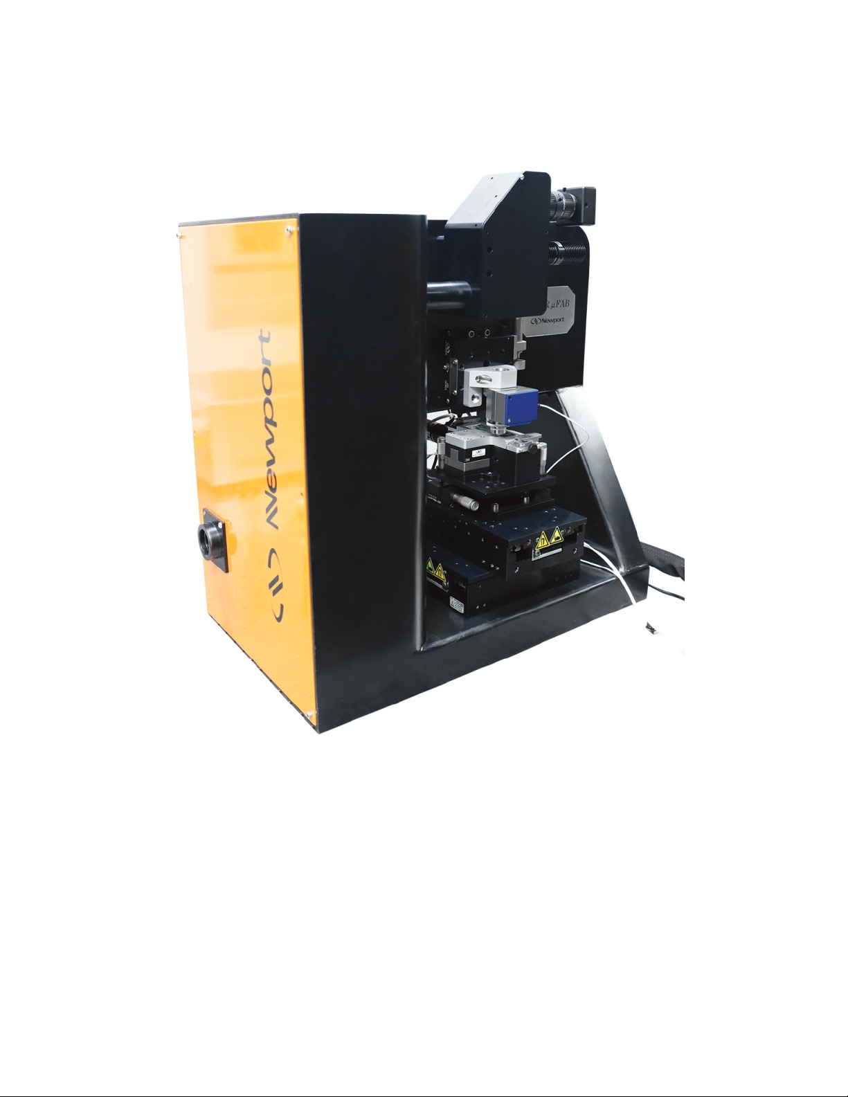
The femtoFBG is a compact workstation for the fabrication of fiber Bragg gratings
(FBGs) using femtosecond lasers direct writing. It is designed to work around amplified
Ti:sapphire (800nm) and ytterbium doped solid state lasers (1040nm/520nm). The
femtoFBG is designed as a research tool for the fast prototyping of FBGs. It employs high
end motion systems in order to move the fiber around a fixed focused laser beam. The
excellent performance of the femtoFBG framework and hardware permits the realization
of FBGs of several lengths and in a variety of fibers with great reliability. An imaging
system within the femtoFBG enabling both transmission and reflective light microscopy
allows for real-time monitoring of the laser process and for aiding the sample alignment
procedure. The femtoFBG comes with a personal computer and software specifically
made for FBGs writing. The femtoFBG software is inherently easy to use because of its
simplicity. Files for the realization of uniform, apodized, and chirped FBGs are easily
produced using the design tools in the femtoFBG software.
2.2 femtoFBG Specifications
Laser wavelengths compatibility: Dual 1040 nm + 520 nm, or 800 nm
Beam entrance height 5 in (126 mm)
Laser power variable attenuation OD0 to OD2
Total travel distance (XYZ) 100 mm x 100 mm x 0.5 mm
Optional upgrade option (Z) 4.8 mm
Resolution and maximum speed (XY) 0.05 µm and 300 mm/s
Resolution and maximum speed (Z) <1 nm and 2 mm/s
Focusing objective 40X, 0.75 NA
Vision system In-line transmission and reflection
microscope imaging
Net Weight 175 lb. (79 kg)
Size (W x H x L) 12 x 20 x 20 in (30.5 x 51 x 51 cm)
(excluding laser and table)
2.3 Unpacking and Handling
It is recommended that the femtoFBG be unpacked in a lab environment. Unpack with
care, ensuring to locate all of the components in the shipping crate. The femtoFBG is
quite heavy in order to limit vibrations and requires at least 2 people to unpack and place
on the optical table where it will operate. Removable handles or lifting straps are
installed for unpacking and moving purposes. They may be removed after the femtoFBG
has been positioned. You are urged to save the packaging material in case you need to
ship or to move the equipment in the future.
2.4 Inspection for Damage
The femtoFBG is carefully packaged at the factory to minimize the possibility of damage
during shipping. Inspect the crate and any packaging material such as boxes or bags for
external signs of damage or mishandling. Inspect the contents for damage. If there is
visible damage to the instrument or components upon receipt, please inform the shipping
company and Newport Corporation immediately.
2.5 Electrical Requirements
The femtoFBG contains several sensitive electronic instruments. Up to 5 electrical plugs
for 110/220 VAC operation are required. Power supplies that features in-line transient
protection and RF filtering should be used, and may be included. In the case that a
device is not compatible with the voltage in your area, please use any enclosed
transformer. Before attempting to power up any electronic instrument for the first time,
the following precautions must be followed:
•
Have a qualified electrician verify the wall socket that will be used is properly
polarized and properly grounded.
•
Set the mains selector tumbler to the voltage that matches the power outlet AC
voltage.
•
Verify the correct rated fuses are installed according to the label attached to the rear
panel
WARNING
TAS optical breadboard is very heavy and requires at least 2
people to lift.
WARNING
Do not attempt to operate this equipment if there is evidence of
shipping damage or you suspect the unit is damaged. Damaged
equipment may present additional hazards to you. Contact
Newport technical support for advice before attempting to plug
in and operate damaged equipment.
WARNING
To avoid electrical shock, connect the instrument to properly
earth-grounded, 3-prong receptacles only. Failure to observe
this precaution can result in severe injury or death.
3 System Overview
The approximate dimensions of the femtoFBG are 12 x 20 x 20 in (30.5 x 51 x 51 cm).
After locating a suitable location on the optical table where to set the system, the
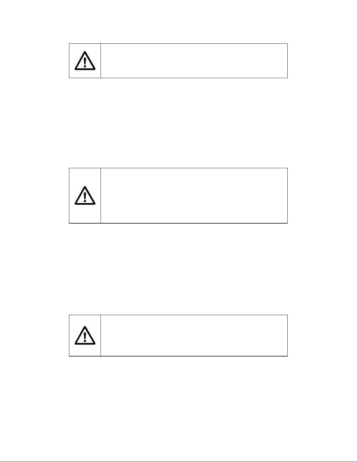
femtoFBG needs to be locked to the table. Figure 1 show an image of the femtoFBG
where the stages and imaging assembly have been removed for demonstration clarity.
This operation can in fact be accomplished with the femtoFBG when completely
configured.
Figure 1. FemtoFBG with stage and imaging assembly removed in order to reveal the locking holes
patterns. Red numbers corresponds to the hole pattern for imperial tables. Blue numbers corresponds to
the hole pattern for metric tables.
The femtoFBG is compatible with both imperial and metric table. The holes pattern 1,2,3
and 4 (Figure 1) is used to lock the femtoFBG to imperial tables. The holes pattern 1,5,6,
and 7 (Figure 2) is used to locked the femtoFBG to metric tables.
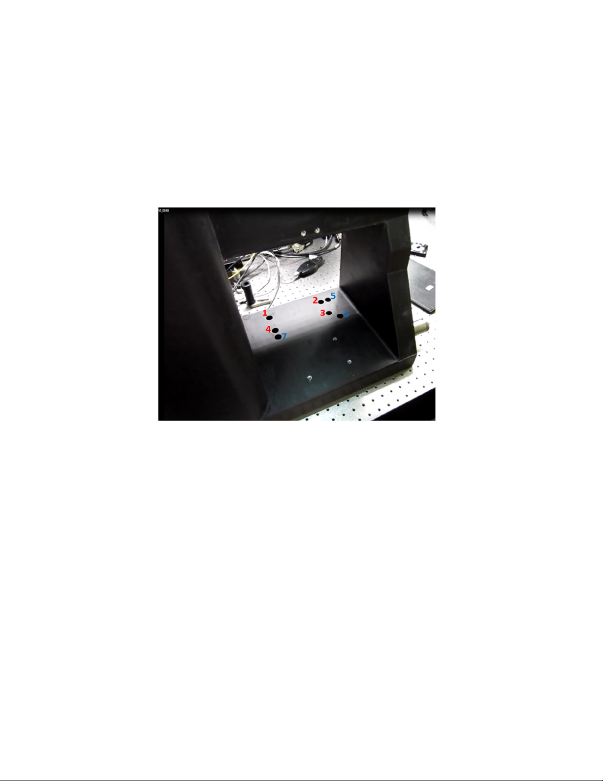
We recommend using at least two mirrors to steer the laser beam into the femtoFBG. A
typical configuration is schematically shown in Figure 2. Two mirrors set at 90° are used
to route the laser beam into the input of the femtoFBG. The beam entrance height of the
femtoFBG is fixed at 5 in (127 mm). This height matches the beam output height of the
Spirit laser. In this case, the routing mirrors need to be set so that the laser beam impinges
in the middle of the mirrors. If a laser with a different beam output height is used, then a
compact periscope is recommended to adjust the laser beam height so to match the
femtoFBG beam entrance port. Mirrors 1 and 2, can be used to steer the laser beam into
the femtoFBG making sure that the laser beam is parallel to the table and makes always
90° turns.
Furthermore, two irises should be used between mirror 1 and 2 in order to aid laser beam
alignment/recovery when necessary in the future. After aligning the laser into the
femtoFBG by walking the beam with mirror 1 and 2, set iris 1 right after mirror 1 and iris
2 right before mirror 2. After setting the location of the irises, their aperture need to be
centered with the laser beam path.
Figure 2. Top-view of the recommended femtoFBG layout with laser and routing optics on the optical
table.
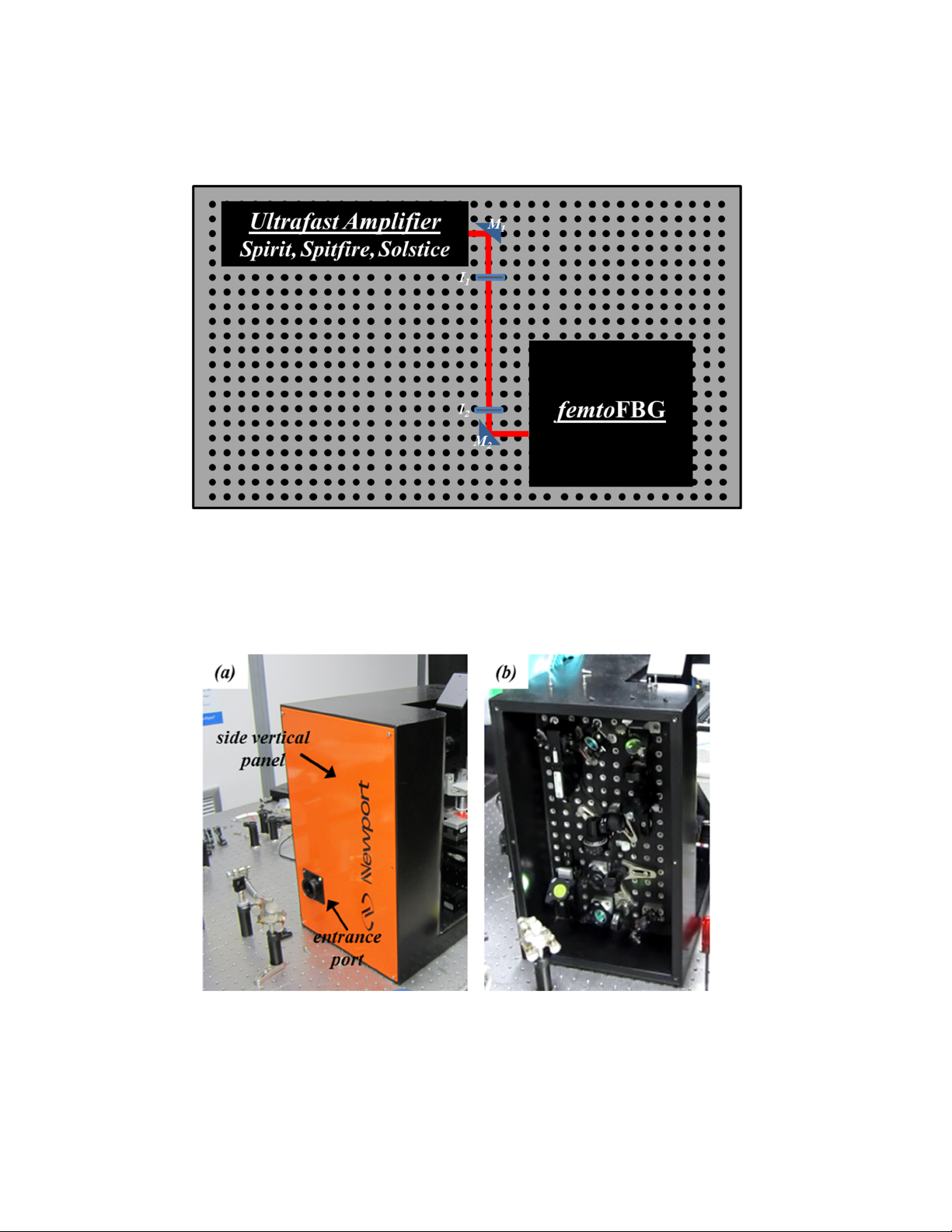
The entrance port of the femtoFBG is located on the vertical left panel as indicated in
Figure 3 (a). Removing this panel, reveals a series of optical elements (Figure 3b) used to
condition the laser beam before entering the focusing/writing assembly.
Figure 3. Vertical side panel of the femtoFBG with laser entrance port (a). Access to a series of optical
elements used for beam conditioning is gained by removing the vertical side panel (b).
A schematic representation of the optical layout within the vertical breadboard of the
femtoFBG is shown in Figure 4 with specific information regarding the different optics.
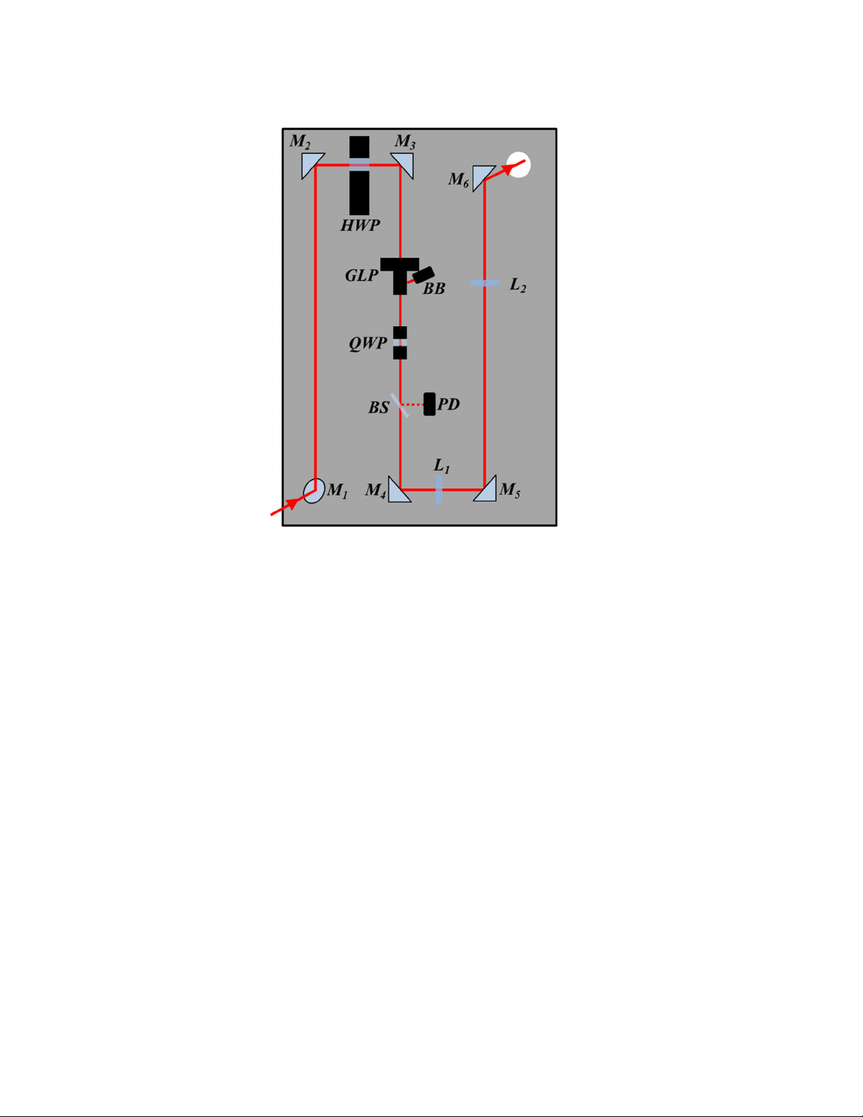
Figure 4. Optical layout of the femtoFBG vertical compartment. M: mirror; HWP: half-wave plate;
GLP: glan-laser polarizer; BB: beam block; QWP: quarter-wave plate; BS: beam sampler; PD:
photodiode; L: lens.
Mirror M
1
is the first mirror the laser beam encounters after entering the input port in the
vertical side panel. M
1
sends the beam vertically to M
2
. The turning mirror M
2
direct the
beam trough a half-wave plate that is mounted in a computer controlled rotational stage.
The bean travels then through a Glan-laser polarizer by means of the turning mirror M
3
.
The combination HWP and GLP is used within the femtoFBG to control the amount the
laser average power delivered to the sample. The polarization of the laser beam is
rendered circular with quarter-wave plate. A beam sampler is used to direct a small
portion of the laser beam to a power meter detector so to have the capability to monitor
the laser average power. M
4
, M
5
, and M
6
are turning mirrors used to direct the laser beam
trough the exit port located in the upper right of the vertical assembly. Two positive
lenses are employed to expand and collimate the laser beam before reaching the focusing
and imaging setup. The second lens (L
2
) assembly rests on a rail so that its position
relative to the position of L
1
can be adjusted.
After going through the optical elements in the vertical side cavity in the femtoFBG, the
laser beam is launched with M6 (Figure 4) into the imaging and focusing setup. Front
views images of this part of the system are shown in Figure 5. A schematic representation
of this section is shown in Figure 6.
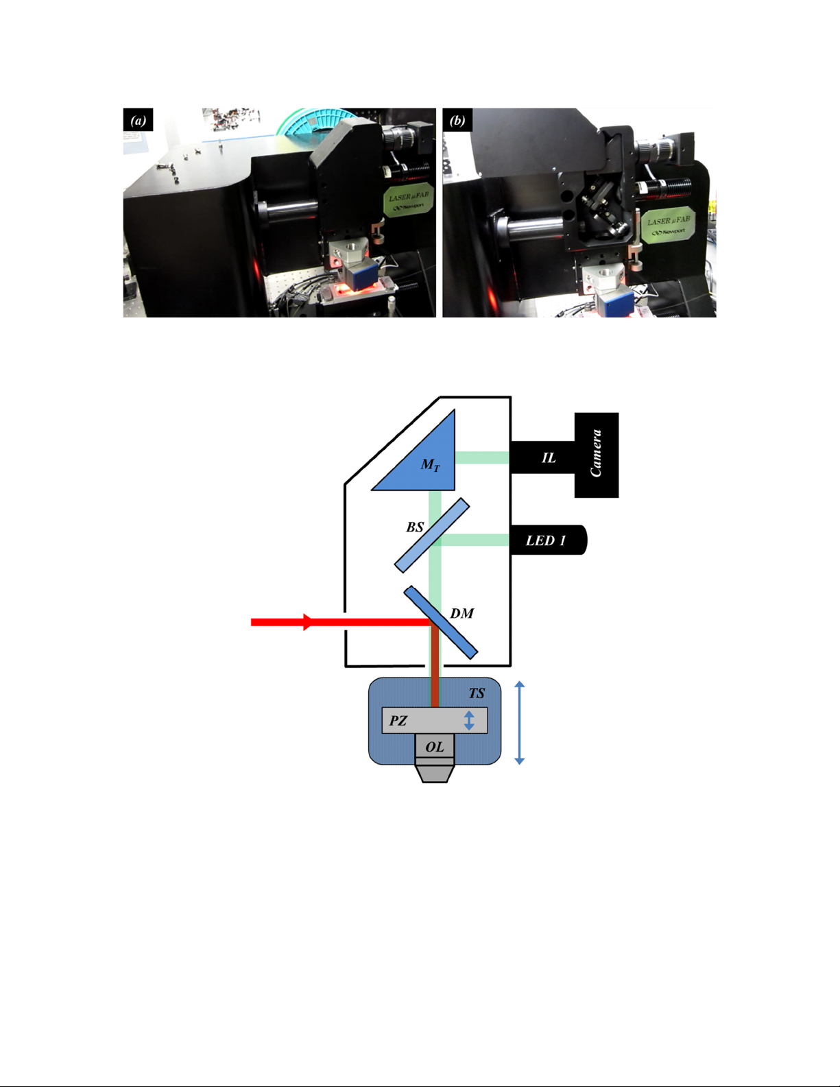
Figure 5. Front view of the imaging and focusing setup in the femtoFBG (a). The imaging setup with
the front cover displaced so to show the optical elements used in it (b).
Figure 6. Optical layout of the femtoFBG imaging and focusing compartments. DM: dichroic mirror;
BS: beam splitter; M
T
: turning mirror; IL: imaging lens system; OL: objective lens; PZ: piezostage; TS:
translational stage.
The first optical element the laser beam encounters at this stage is the dichroic mirror
(DM) which reflects the laser beam into the microscope objective lens (OL) and transmits
the light used for both reflective and transmission light microscopy. A CMOS camera in
combination with a lens assembly (IL) is used for imaging. The output of a LED (LED 1)
is reflected toward the microscope with 50:50 beam splitter (BS). The reflected part of
the LED 1 light from the sample travel back to the beam splitter and a portion of it
reaches the CMOS camera by means of the turning mirror (M
T
) and IL forming a
reflected image of the sample in the field of view of the OL. The position of the laser
focal plane in the sample can be adjusted with great precision with a computer controlled
piezo collar stage (PZ) which moves the OL vertically. Furthermore, the whole OL
assembly is mounted on a manual vertical stage that allows for coarse adjustments of the
laser focal plane.
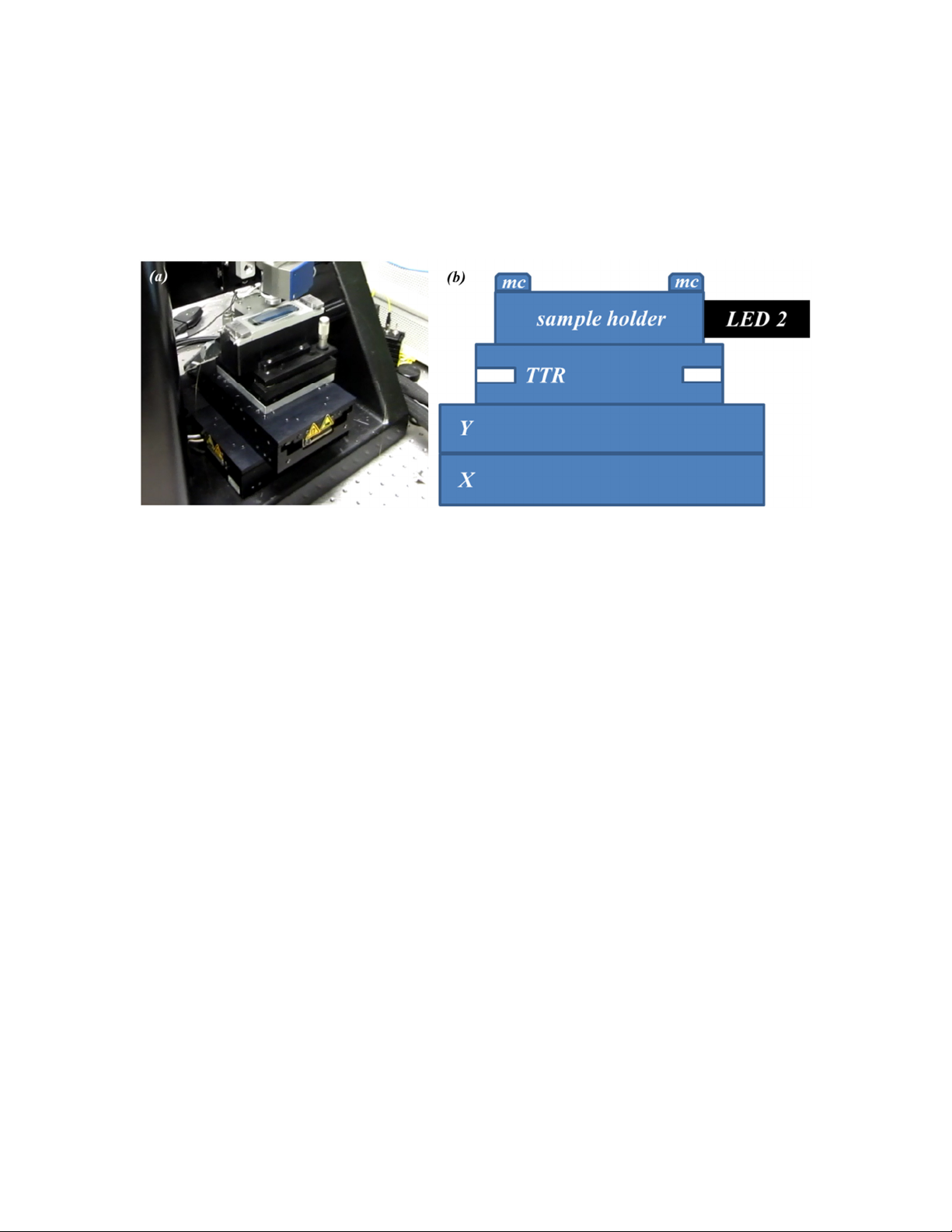
Figure 7. Image of the sample assembly showing the motorized and manual stages, and the custom
sample holder (a). Schematic of the sample assembly of the femtoFBG (b). X: motorized stage for the x
direction; Y: motorized stage for the y direction; TTR: manual tilt, tip, and rotation stage; MC: magnetic
clamps.
The sample assembly of the femtoFBG is located below the microscope objective lens
and it consists of several components (Figure 7). Two computer controlled motorized
stages (XMS160) are stacked on top of each other in order to give the ability to move the
sample around the focused laser bean with great precision in both the x and y directions.
Above these two stages, lays a manual multi-axis platform capable of rotation, tilt, and
tip motions. Finally, a custom made sample holder tops the assembly. The holder is
capable of receiving microscope slides with dimensions of 75 x 25 x 1 mm. The sample
holder has two magnetic clamps at its ends that are used to keep the fiber steady during
laser processing. Moreover, the sample holder accepts the output of a LED (LED 2),
which illuminates the sample for acquiring images by transmission light microscopy. A
set of 45° mirrors within the sample holder reflect the output of LED 2 up into the sample
and the microscope objecting. The light follows then the same pathway described earlier
and it reaches the CMOS camera.
The CMOS camera is connected to the imaging setup vial a lens assembly (IL, figure 6).
IL assembly relies the sample image captured by the OL into the CMOS camera using a
variable focus. To ensure that the imaging and the laser writing planes coincide in the
sample, the variable focus know of the IL assembly is set to infinity. An iris is present
also in the IL assembly and it set to be completely open to allow maximum light
throughput. An image indicating the locations of the variable focus and iris knobs in the
IL assembly is shown in Figure 8.
The turning mirror M
T
in Figure 6 is used to center the image captured by the OL in the
CMOS active area. Tilt and tip adjustments of M
T
are shown in Figure 9 and can be
reached using an Allen wrench.

Figure 8. Lens assembly (IL) in the imaging setup; the locations of the IL variable focus and iris knobs
are highlighted.
Figure 9. Location of the tilt and tip adjustments of the turning mirror MT in the imaging setup.
4 Alignment Procedure
Before starting the alignment of the laser beam through the optical layout of the
femtoFBG vertical compartment, it is important to center M
1
(Figure 4) with the input
laser beam. A 1” diameter reticle may be used during installation to accomplish this task.
Remove M
1
from its mount and replace it with the provided reticle. Use routing mirror
M
2
(Figure 2) to position the laser beam on the center of the reticle. Remove the reticle
and replace it with M
1
(Figure 4). At this point, the laser beam can be walked using the
mirrors in the vertical cavity (M
2
to M
6
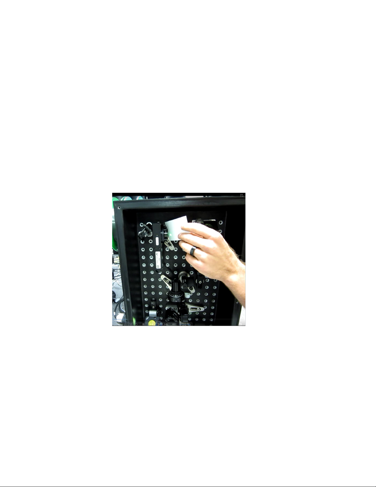
) to achieve a proper alignment. The goal at this
stage is to have the laser beam travelling through the center of each optical element. A
white piece of paper can be used to check the quality of the laser beam as shown in
Figure 10. Specifically, if signs of clipping or diffraction are observed that indicates a
laser beam poorly aligned. A round beam pattern with a smooth intensity profile indicates
instead a well aligned laser beam. Care must be used when performing this task between
L
1
and L
2
(Figure 4) because of the presence of a focusing plane.
Figure 10. During the alignment of the laser beam within the optical layout of the vertical compartment
of the femtoFBG, a white piece of paper can be used to check the beam quality after each optical
element.
Every femtoFBG is fully tested in Technology and Applications Center of Newport
Corporation before being shipped to customers. During these tests, the system is carefully
aligned. A Newport’s sales engineer will setup the femtoFBG in the customer’s lab as
part of the sales agreement. After installation, the femtoFBG will be ready for the
customer use.
At this point the laser beam exits the vertical compartment of the femtoFBG through M6
(Figure 4) and it is now launched to the focusing and imaging system. The DM in the
imaging setup (Figure 6) reflects the laser beam into the microscope objective lens (OL).
A white piece of paper is used again to check that the laser beam centers the back
aperture of the OL and also to verify that the beam is not clipped and/or diffracted. The
beam must show a clean and round pattern as shown in Figure 11(a). Furthermore, the
same method is used to check the laser beam after the OL in order to ensure that the laser
beam goes straight through it. Because of the large OL numerical aperture, we
recommend checking this while the beam is defocusing such as in Figure 11(b).
Figure 11. The shape and size of the laser beam is visually inspected with the aid of a white piece of
paper before (a) and after (b) the OL.
In the vertical compartment of the femtoFBG, L
1
and L
2
are used to expand the laser
beam diameter so to match or overfill the diameter of the OL back aperture. It is
important to perform this task in order to take full advantage of the OL numerical
aperture and hence achieve the smallest beam diameter at the OL focal plane. To test the
size and collimation of the laser beam after L
1
and L
2
, a temporary mirror in a 45° mount
is used before the OL to project the laser beam at a distance.
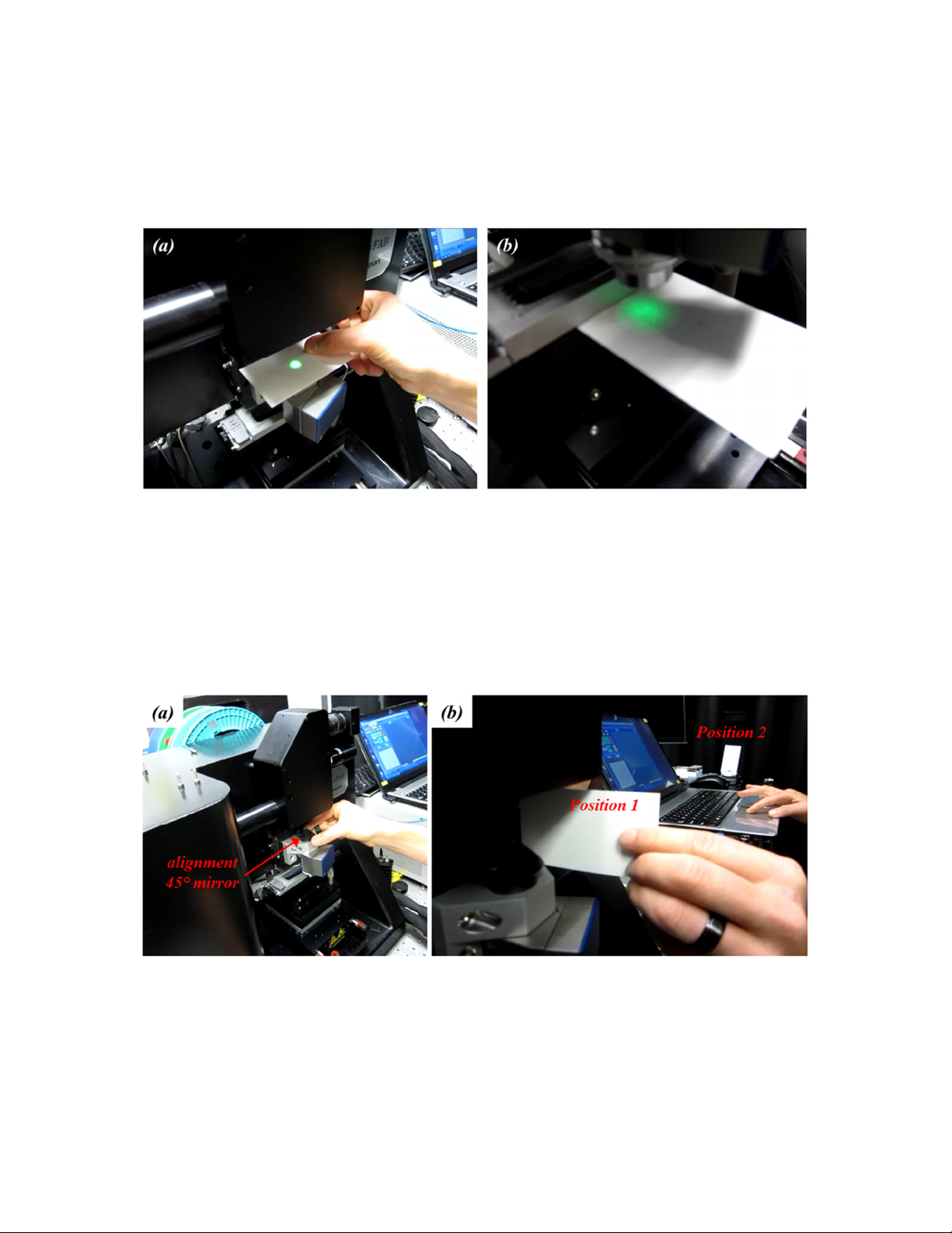
Figure 12. An auxiliary mirror mounted at 45° is sued to check the laser beam collimation. The 45°
mirror is positioned just before the OL entrance (a). With the aid of a piece of paper, the laser beam
diameter is checked in two positions, one close and one far to the 45° mirror (b).
Figure 12 (a) shows where to rest the 45° mirror in the metallic bracket that holds the
piezo focusing stage and the OL; ensures that the laser beam does not clip the 45° mirror.
Figure 12 (b) illustrates the locations where to check the laser beam diameter. If L
1
and

L
2
are positioned at the right distance with each other, the laser beam diameter will
remain constant between position 1 and 2, and it will show a characteristic round profile.
If the test in Figure 12 (b) shows a converging or diverging beam, L
1
and L
2
are not in the
correct positions. In order to fix this eventual problem, L
2
is mounted on a rail and so its
position can be easily adjusted along the beam path. In this case, L
2
position is changed
until a collimated laser beam is obtained as measured with the method described in
Figure 12 (b).
Once the laser beam diameter has beam checked and found to be collimated, it can be
sent through the OL. If the laser beam is not travelling along the OL main axis, the laser
beam exiting the OL will not looked like the one in 11 (b). It will instead shows signs of
clipping where a portion of the beam is missing. To recover this part of the system
alignment, the last mirror of the vertical compartment M
6
(Figure 4) and the DM (Figure
6) are going to be used to walk the beam back to its original path. The tilt and tip
adjustments of M6 are used to center the laser beam in the OL back aperture. The tilt and
tip adjustments of the DM are used to obtain a clean and symmetric laser beam after the
OL (Figure 11b). This process is repeated several times until a satisfactory alignment is
achieved.
To access the tilt and tip adjustments of the DM, the front cover of the imaging and
focusing compartment needs to be removed. The tilt adjustment is accessed by means of
a through hole in the casing using an Allen wrench. The tip adjustment can be reach by
hand using dedicated knob. Images of these two locations within the imaging and
focusing compartment for the femtoFBG are shown in Figure 13.
Figure 13. Images of the femtoFBG compartment containing the DM. The location of the DM tilt
adjustment is shown in (a), while the location of the DM tip adjustment is shown in (b).

5 Sample Preparation and Loading
Femtosecond laser direct writing is performed using the femtoFBG by moving a clamped
fiber with a high precision stage assembly around a fixed and focused laser beam. The
pattern written in the fiber core can easily be programmed using the provided femtoFBG
software (Chapter 6). The fiber is sandwiched between a microscope slide (for instance,
Ted Pella 26008, 75 x 25 x 1 mm, a starter package is included with the system) and a
microscope cover-slip (for instance, Ted Pella 260360, No. 1, 24 x 60 mm, a starter
package is included with the system). The space between the microscope slide and the
cover-slip is filled with an index-matching gel (for instance, Cargille cat# 24317; not
included). This last action is taken to achieve the highest degree of FBGs manufacturing.
The gel eliminates spherical aberrations due to the change of index of refraction and to
the cylindrical geometry of the fiber. The following is the description to how to prepare
the sample and load it in the femtoFBG.
•Using the joystick in the Move window of the software, position the center of the
sample holder under the exit of the OL.
•Set this position as the origin; new coordinates for this position are now 0, 0, 0.
•With a spacer (for example a PS-0.25 pedestal spacer from Newport can be used),
raise the OL by moving upward the manual TS (Figure 6). A picture of how to
perform this task is shown in Figure 14.
•Using the joystick, move one axis of the stage assembly out, as shown in Figure
15. In this new location, the sample holder area is more accessible.
•Open the MC (Figure 7) and insert the microscope slide in the sample holder
opening as shown in Figure 16.
•Load the fiber to be processed in the sample holder on top of the microscope slide
as shown in Figure 17. The fiber rests in V-grooves of the magnetic clamps.
•Close the magnetic clamps making sure not to cleave or damage the fiber.
Holding the fiber in the V-groove with one hand, use the other hand to close the
clamp as shown in Figure 18. Perform this task on both side of the sample holder
to secure the fiber.
•Holding the fiber in one hand, open the adjacent magnetic clamp and pull the
fiber outward. Close the magnetic clamp while gently pulling the fiber. This step
ensures the fiber to be straight between the two clamps.
•Add two spacers on each side of the fiber as shown in Figure 19. The spacer
consists of a short piece of unstripped SMF28 fiber. You can sacrifice two
approximately 55 mm long portions of your fiber to be modified, to match the
diameter. The role of the spacers is two-fold; they help in containing the index-
matching gel and they provide the support required to hold the microscope cover-
Table of contents
Other Newport Desktop manuals

Popular Desktop manuals by other brands


Metacentre
Metacentre Y10META13.00 Technical manual

HP
HP dx1000 - Microtower PC Illustrated parts & service map

Panasonic
Panasonic TOUGHBOOK CF-19FHGAX M Series Service manual

Shuttle
Shuttle XPC slim user guide

HP
HP Pavilion t500 - Desktop PC Technical specifications

Lenovo
Lenovo ThinkCentre M92z Guia do usuário