Newport PLATINUM Series User manual

DasyLAB MODBUS Interface Manual

Additional products from
Counters
Frequency Meters
PID Controllers
Clock/Timers
Printers
Process Meters
On/Off
Controllers
Recorders
Relative
Humidity
Transmitters
Thermocouples
Thermistors
Wire
Wireless
Rate Meters
Timers
Totalizers
Strain Gauge
Meters
Voltmeters
Multimeters
Soldering Iron
Testers
pH pens
pH Controllers
pH Electrodes
RTDs
Thermowells
Flow Sensors
For Immediate Assistance
In the U.S.A. and Canada: 1-800-NEWPORT
®
In Mexico: (95) 800-NEWPORT
SM
Or call your local NEWPORT Office.
The information contained in this document is believed to be correct but NEWPORT Electronics, Inc. accepts
no liability for any errors it contains, and reserves the right to alter specifications without notice.
WARNING: These products are not designed for use in, and should not be used for, patient connected applications.
TRADEMARk NOTICE: ®
,
®
NEWPORT, NEWPORT®,and newportUS.com are trademarks of NEWPORT
Electronics, Inc.
This device is marked with the international caution symbol. It is important to read the Setup Guide before
installing or commissioning this device as it contains important information relating to safety and EMC.
Newport Electronics, Inc.
2229 South Yale Street
Santa Ana, CA 92704
www.newportUS.com

DasyLab Platinum Modbus Interface
Revision 1.0 Page 1 of 11
Table of Contents
1Introduction........................................................................................................... 2
1.1 Purpose....................................................................................................................2
1.2 Definition of Terms and Acronyms ........................................................................2
1.3 Applicable Documents............................................................................................3
2Modbus Interface.................................................................................................. 4
2.1 Modbus Functions ..................................................................................................4
2.2 Data Formats ...........................................................................................................4
2.2.1 Multiple Register Reads........................................................................................................ 4
2.2.2 Multiple Register Writes ........................................................................................................5
2.2.3 Request Packet Sizes........................................................................................................... 5
2.2.4 Modbus USB Support ...........................................................................................................6
3Platinum Modbus Register Assignments........................................................... 7
3.1 DasyLab Platinum Modbus Registers....................................................................7
3.2 DasyLab Platinum Modbus Register Access ........................................................8
3.3 Example ...................................................................................................................9
3.3.1 Serial inteface........................................................................................................................9
3.3.2 TCP/IP Interface..................................................................................................................11

DasyLab Platinum Modbus Interface
Document Number Revision 1.0 Page 2 of 11
For Internal Use Only: This document contains confidential, proprietary information of Omega Engineering/Newport Electronics,
The Document may not be copied or reproduced without the prior, written permission of Omega Engineering/Newport Electronics
1 Introduction
1.1 Purpose
The following document defines the Modbus protocol support and register mapping used by the
Platinum product allowing interfacing to the DasyLab Modbus interface software.
The Modbus interface is available on all communication channels and support is provided for
MODBUS/ASCII, MODBUS/RTU and MODBUS/TCP/IP transactions.
1.2 Definition of Terms and Acronyms
I2C 2 wire serial interface
Base Device Device connected to slave device
Smart Input Device supporting 1 or more Input sensors
Smart Output Device supporting 1 or more Output Elements
Sensor Element One of the physical sensing elements on a Smart Output
AC Alternating Current
DC Direct Current
CS Chip Select
ADC Analog to Digital Converter
DAC Digital to Analog Converter
RS485 Electrical signals used for serial communications
RS232 Electrical signals used for serial communications
CSV Comma Separated Values
COTS Commercially-Off-The-Shelf
ESD Electo Static Discharge
FW Firmware
HW Hardware
I/O Input/Output
LED Light Emitting Diode
Hexadecimal Values expressed using base 16 (24)

DasyLab Platinum Modbus Interface
Document Number Revision 1.0 Page 3 of 11
For Internal Use Only: This document contains confidential, proprietary information of Omega Engineering/Newport Electronics,
The Document may not be copied or reproduced without the prior, written permission of Omega Engineering/Newport Electronics
1.3 Applicable Documents
Doc. # Name / Description Rev. #
Platinum Modbus Interface Reference 1.0
Platinum Load and Save File Format 0.0.1
Platinum Ramp and Soak Processing
0.0.1
MODBUS APPLICATION PROTOCOL SPECIFICATION
V1.1b3
Device Serialization and Version Information Rev 0.1
Omega Engineering Coding Standard Rev 1.2.0

DasyLab Platinum Modbus Interface
Document Number Revision 1.0 Page 4 of 11
For Internal Use Only: This document contains confidential, proprietary information of Omega Engineering/Newport Electronics,
The Document may not be copied or reproduced without the prior, written permission of Omega Engineering/Newport Electronics
2 Modbus Interface
The Modbus interface is fully described in MODBUS APPLICATION PROTOCOL SPECIFICATION
(V1.1b3).
The Modbus specification allows accessing to up 65535 internal ‘holding’ registers using register
READ, register WRITE and WRITE MULTIPLE commands. Each Modbus holding register is defined
as a 16 bit entity structured as BIG ENDIAN values (most significant byte always presented first).
The Platinum Modbus interface provides access to the internal database of the Platinum product
family by internally mapping Modbus holding registers to specific database items.
Modbus is structured using a MASTER-SLAVE topology, in which there is one MASTER device and
up to 255 slave devices. All transactions are initiated by the MASTER device.
Modbus slave devices are individually accessed using a one byte SLAVE address. The MASTER
device initiates a transaction by sending a request packet to a specific slave. The SLAVE device
processes the transaction and returns either response packet indicating success or failure.
Address 0 is reserved as a ‘broadcast’ address, in which all slave devices will accept and process the
transaction but will not send a response.
2.1 Modbus Functions
The Platinum Modbus interface supports the following Modbus FUNCTION requests.
Function
Code Mnemonic Description
0x03 Read Holding Register Reads one or more consecutive 16 bit holding registers
0x06 Write Single Register Writes a specific 16 bit holding register
0x07 Read Exception status Reads structured status information
0x08 Diagnostic Read/Write diagnostic information
0x10 Write Multiple Registers Write one or more consecutive 16 bit holding registers
0x0b Get Comm events Read communication event counters
2.2 Data Formats
Modbus holding registers are represented as 16 bit entities. The following encoding is used for
extended data items. Note that ‘byte 0’ will be the first byte received/transmitted.
For data types that can be represented in 16 bit (Boolean, byte, char, int16 and uint16) a single
register is used.
For data types that require 32 bits two consecutive registers are used. The lower number register will
represent the most significant data. The 2nd register represents the leas significant data.
2.2.1 Multiple Register Reads
When reading a dual register entity the lower order register should be used as the requested ‘holdiing
register’, with a request for a minimum of 2 registers. Internally the entire entity is read and data is
then built into a response packet.

DasyLab Platinum Modbus Interface
Document Number Revision 1.0 Page 5 of 11
For Internal Use Only: This document contains confidential, proprietary information of Omega Engineering/Newport Electronics,
The Document may not be copied or reproduced without the prior, written permission of Omega Engineering/Newport Electronics
The access can be split into 2 consecutive single register reads. When the lower (base) register is
accessed the entire 32 bit entity is read and the two most significant bytes are returned. The following
single register read must specify the next consecutive register address. The two least significant
bytes of the internally buffered data used in the response.
Attempts to access the two least significant bytes without first reading the two most significant bytes
will result in an error response.
2.2.2 Multiple Register Writes
When writing a dual register entity the lower order register should be used as the requested ‘holdiing
register’, with a request for minimum of 2 registers. The write data is internally buffered and
transferred to the database entry as a 32 bit value.
The access can be split into 2 consecutive single register writes. When the lower (base) register is
written the 16 bit entity is internally buffered BUT NO DATA TRANSFER IS MADE TO THE
DATABASE. The following single register write must specify the next consecutive register address.
The two least significant bytes of the write request are combined with the previous write data and the
entire 32 bit entity is written to the database.
Attempts to write the two least significant bytes without first writing the two most significant bytes will
result in an error response.
Data
Types Number
of
Registers
Byte Description
0 1 2 3
Boolean 1 -- LSB
N/A
Zero = OFF, non-zero = ON
Byte,
Char 1 -- LSB Entity contained in LSB of register,
Byte 0 ignored.
Int16,
uint16 1 MSB LSB Entity contained in MSB/LSB of
register.
0 1 2 3 (dual register data)
Int32,
uint32 2 MSB B-1 B-2 LSB Requires 2 consecutive registers,
MSB transferred first
float 2 Sign+
Exp Mantisa
MSB B-1 Mantisa
LSB IEEE formatted value contained in 2
consecutive register
2.2.3 Request Packet Sizes
Multiple consecutive registers may be accessed in a single transaction.
The Platinum Modbus interface imposes a maximum of 64 bytes for the total transaction. Allowing for
the required framing, addressing and integrity checks results in the following data size restrictions
using the READ and WRITE MULTIPLE functions.
Format Protocol Overhead Maximum Read data Maximum Write data
ASCII 16 12 Registers 12 Registers
RTU 8 23 Registers 23 Registers
TCP/IP 8 23 Registers 23 Registers

DasyLab Platinum Modbus Interface
Document Number Revision 1.0 Page 6 of 11
For Internal Use Only: This document contains confidential, proprietary information of Omega Engineering/Newport Electronics,
The Document may not be copied or reproduced without the prior, written permission of Omega Engineering/Newport Electronics
2.2.4 Modbus USB Support
The Modbus specification supports RS232 and RS485 serial data. For ASCII formatted packets a
USB virtual comm channel provides full support since the framing information is specified by unique
characters (SOF = ‘:’, EOF = CR/LF).
For RTU formatted packets the Modbus requires specific inter-frame character timing to determine
the framing of each transaction. This information is not available using a generic virtual comm
channel across USB, which will typically collect ‘serial’ data into 64 byte packets for transmission, as
determined by the USB end-point buffer size. The USB Modbus RTU interface relies on the USB
channel collecting data into 64 byte packets.

DasyLab Platinum Modbus Interface
Document Number Revision 1.0 Page 7 of 11
For Internal Use Only: This document contains confidential, proprietary information of Omega Engineering/Newport Electronics,
The Document may not be copied or reproduced without the prior, written permission of Omega Engineering/Newport Electronics
3 Platinum Modbus Register Assignments
All accesses to the Platinum database information are made through the Modbus registers.
Mnemonic entries marked with ‘*’ are identical to those used by the Platinum LOAD and SAVE file
formats.
Mnemonic entries marked with ‘**’ are identical to those used by the Platinum LOAD and SAVE file
formats but are referenced in LOAD and FILE data are made using meta characters (%).
Data types are:
R – single 16 bit register (may be Boolean, byte, char, int16 or uint16 data)
L – dual (32 bit) register (may be int32 or uint32 data)
F – IEEE Floating point value
All data is transferred using BIG ENDIAN formatting, where the most significant byte is transmitted
first.
3.1 DasyLab Platinum Modbus Registers
The following is an abbreviated list of the more common registers within a Platinum controller. Refer
to the Platinum Modbus Interface document for a complete list.
Index
Mnemonic
Type
Description
512
0x0200
DEVICE_ID**
L
Device Identifier
514
0x0202
VERSION_NUMBER**
L
Device Version number (Hex Value)
516
0x0204
SYSTEM_STATUS
L
Enumerated Status value
528
0x0210
CURRENT_INPUT_VALUE
F
Measured process input value
532
0x0214
REMOTE_SETPOINT_VALUE
F
Measured auxiliary input value
542
0x021e
INPUT_DIGITAL
R
State of digital input pin
544
0x0220
CURRENT_SETPOINT_1
F
Current value of Setpoint 1
546
0x0222
CURRENT_SETPOINT_2
F
Current value of Setpoint 2
548
0x0224
CONTROL_SETPOINT
F
Setpoint used in PID calculations
550
0x0226
PEAK_VALUE
F
Maximum Value processed
552
0x0228
VALLEY_VALUE
F
Minimum Value processed
554
0x022a
PID_OUTPUT
F
PID Output level (0..100%)
556
0x022c
CURRENT_INPUT_VALID
R
Flag indicating process value is valid
557
0x022d
ALARM_STATE
R
558
0x022e
RAMP_SOAK_STATE
R
Enumerated value - R&S state
560
0x0230
OUTPUT_1_STATE
R
Flag indicating state of Output (0/1)
561
0x0231
OUTPUT_2_STATE
R
Flag indicating state of Output (0/1)
562
0x0232
OUTPUT_3_STATE
R
Flag indicating state of Output (0/1)
563
0x0233
OUTPUT_4_STATE
R
Flag indicating state of Output (0/1)
DasyLab Platinum Modbus Interface
Document Number Revision 1.0 Page 8 of 11
For Internal Use Only: This document contains confidential, proprietary information of Omega Engineering/Newport Electronics,
The Document may not be copied or reproduced without the prior, written permission of Omega Engineering/Newport Electronics
564
0x0234
OUTPUT_5_STATE
R
Flag indicating state of Output (0/1)
565
0x0235
OUTPUT_6_STATE
R
Flag indicating state of Output (0/1)
566
0x0236
OUTPUT_7_STATE
R
Flag indicating state of Output (0/1)
567
0x0237
OUTPUT_8_STATE
R
Flag indicating state of Output (0/1)
Control Functions
576
0x0240
RUN_MODE
R
Enumerated value – system running state
578
0x0242
LATCH_RESET
R
Write 1 to reset latched alarms
Alarm Configuration
1280
0x0500
ALARM_1_STATE
R
Alarm state (Bit 0)
1312
0x0520
ALARM_2_STATE
R
Excitation Voltage
1472
0x05c0
EXCITATION_VOLTAGE*
R
Enumerated Excitation Voltage
Annunciators
1504
0x05e0
DB_ANNUNCIATOR_1_STATE
R
Enumerated Annunciator State
1508
0x05e4
DB_ANNUNCIATOR_2_STATE
R
Enumerated Annunciator State
3.2 DasyLab Platinum Modbus Register Access
The following specifications have been verified with DasyLab version 13. Refer to DasyLab specific
documentation for further details.
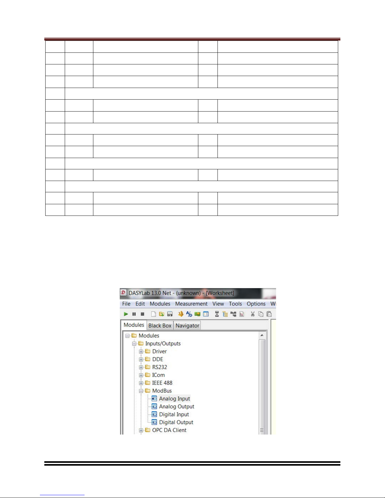
The DasyLab software package allows the integration of Modbus compatible equipment through the
Modbus Input/Output Module. All Platinum registers are treated as Analog INPUT or Analog OUTPUT
values. Use Modbus Analog Input module to request data from Platinum and use Modbus Analog
Output module to send data to Platinum.
DasyLab Platinum Modbus Interface
Document Number Revision 1.0 Page 9 of 11
For Internal Use Only: This document contains confidential, proprietary information of Omega Engineering/Newport Electronics,
The Document may not be copied or reproduced without the prior, written permission of Omega Engineering/Newport Electronics
DasyLab supports Modbus RTU (serial) and Modbus TCP/IP (Ethernet). The Platinum controller
supports Modbus RTU on the USB interface, the RS232/RS485 interface (if installed) and Modbus
TCP/IP on the Ethernet interface (if installed). For the serial channel and USB connections the correct
COM channel must be selected and for serial channels the appropriate INTERFACE parameters
must be chosen. The Platinum unit must have its corresponding COM parameters set accordingly.
If using serial interface, DASYLab assumes the function of the master which sends commands to the
measurement devices or slaves. If using TCP/IP interface, DASYLab assumes the function of the
client which requests data from the server.
3.3 Example
3.3.1 Serial interface
In the example shown, the Platinum controller has been connected using a USB cable and appears
as ‘Virtual COM Port’ 256 within the Windows environment. For USB connections the serial interface
parameters are ignored. The Platinum /INIT/COMM/USB/PROT (front panel access menu) has been
set to MODBUS/RTU.
The Register Starts at 0 option should be checked. The ‘30’ Pull Down option may be ignored. All
values are accessed using BIG ENDIAN format and the ‘swap word order’ option should remain
unchecked.
When a Modbus Input/Output module is placed it is necessary to link the associated values with the
correct Platinum Modbus registers. DasyLab requires that register values are entered as decimal
values.
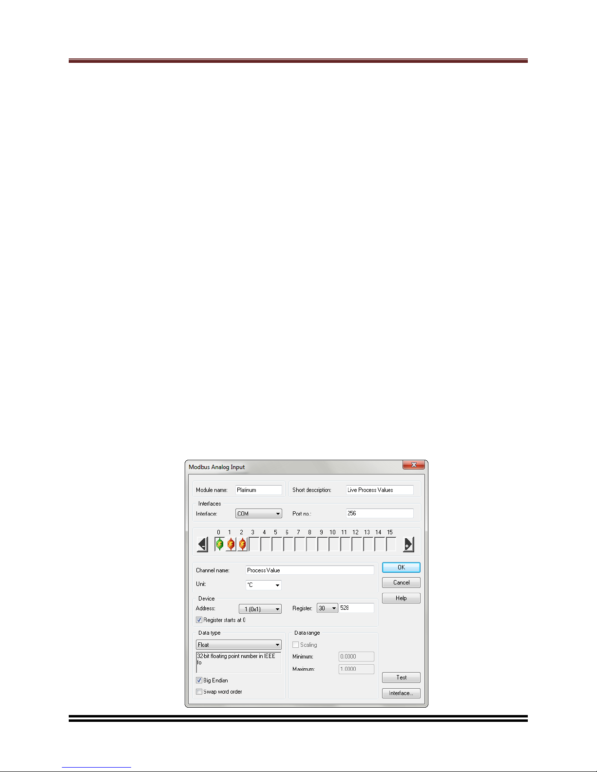
The following example shows how Modbus Analog Input module can be configured.
On Analog Input Channel 0, the channel is named as Process Value with Celsius temperature unit.
The register index is 528 (Register starts at 0) and the Register data type is Float (32 bit). The Device
Address is 0x01.
On Analog Input Channel 1 and 2 (not shown), Peak Value and Valley Value are configured with the
matching Register index and Data type that can be found in Platinum Series User Manual -
Modbus Interface document.
DasyLab Platinum Modbus Interface
Document Number Revision 1.0 Page 10 of 11
For Internal Use Only: This document contains confidential, proprietary information of Omega Engineering/Newport Electronics,
The Document may not be copied or reproduced without the prior, written permission of Omega Engineering/Newport Electronics
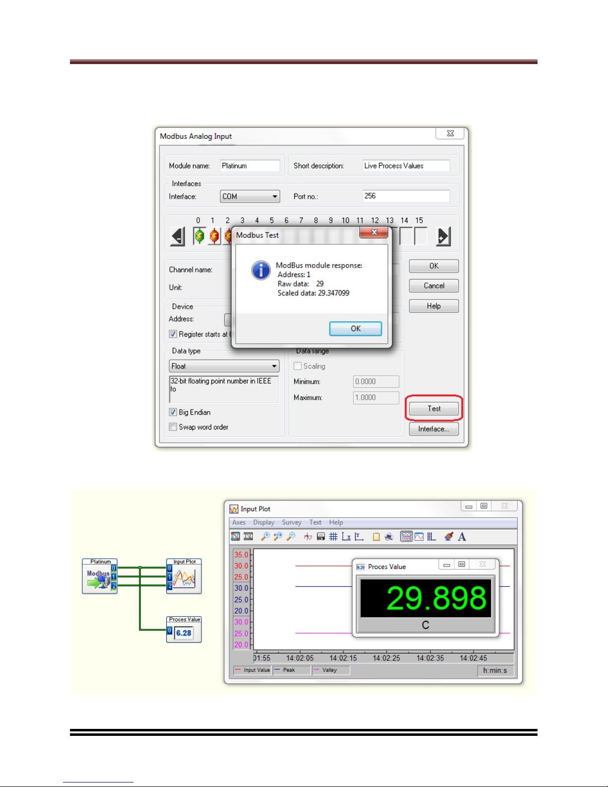
To quickly test communication to Platinum controller with Modbus Analog Input module, click on
“Test” and the data returned from the device is displayed in “Scaled data” as shown in the screenshot
below.
Once the Modbus Analog Input module is configured, it can then be connected to Display modules
such as Digital display or Chart Recorder module which can be found in Display category.
DasyLab Platinum Modbus Interface
Document Number Revision 1.0 Page 11 of 11
For Internal Use Only: This document contains confidential, proprietary information of Omega Engineering/Newport Electronics,
The Document may not be copied or reproduced without the prior, written permission of Omega Engineering/Newport Electronics
3.3.2 TCP/IP Interface
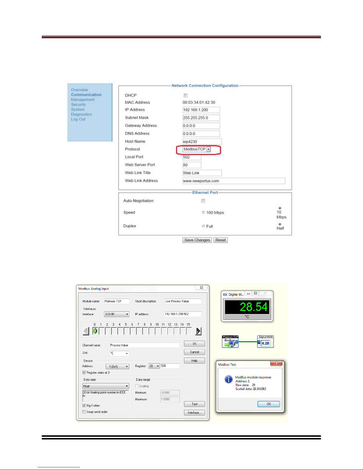
In this example, Modbus communication to Platinum is through TCP/IP interface. The TCP
communication protocol needs to be changed to ModbusTCP. This setting can be found on
Communication page/Network Connection Configuration section. The default device IP address of
Platinum’s TCP/IP interface is 192.168.1.200 and the default Modbus Local Port is 502.
Platinum Ethernet communication protocol also needs to be changed to Modbus/RTU. This setting is
accessible through the front panel menu /INIT/COMM/ETHN/PROT.
The setup procedure for DasyLab Modbus over TCP/TIP is similar to DasyLab Modbus Serial. The
following screenshot illustrates a typical configuration.

Warranty/Disclaimer
NEWPORT Electronics, Inc. warrants this unit to be free of defects in materials and workmanship for a period of one
(1) year from the date of purchase. In addition to NEWPORT’s standard warranty period, NEWPORT Electronics
will extend the warranty period for four (4) additional years if the warranty card enclosed with each instrument is
returned to NEWPORT.
If the unit should malfunction, it must be returned to the factory for evaluation. NEWPORT’s Customer Service
Department will issue an Authorized Return (AR) number immediately upon phone or written request. Upon
examination by NEWPORT, if the unit is found to be defective it will be repaired or replaced at no charge.
NEWPORT’s WARRANTY does not apply to defects resulting from any action of the purchaser, including but not
limited to mishandling, improper interfacing, operation outside of design limits, improper repair, or unauthorized
modification. This WARRANTY is VOID if the unit shows evidence of having been tampered with or shows evidence
of being damaged as a result of excessive corrosion; or current, heat, moisture or vibration; improper specification;
misapplication; misuse or other operating conditions outside of NEWPORT’s control. Components which wear are
not warranted, including but not limited to contact points, fuses, and triacs.
NEWPORT is pleased to offer suggestions on the use of its various products. However, NEWPORT neither
assumes responsibility for any omissions or errors nor assumes liability for any damages that result from
the use of its products in accordance with information provided by NEWPORT, either verbal or written.
NEWPORT warrants only that the parts manufactured by it will be as specified and free of defects.
NEWPORT MAKES NO OTHER WARRANTIES OR REPRESENTATIONS OF ANY KIND WHATSOEVER,
EXPRESSED OR IMPLIED, EXCEPT THAT OF TITLE, AND ALL IMPLIED WARRANTIES INCLUDING
ANY WARRANTY OF MERCHANTABILITY AND FITNESS FOR A PARTICULAR PURPOSE ARE HEREBY
DISCLAIMED. LIMITATION OF LIABILITY: The remedies of purchaser set forth herein are exclusive and
the total liability of NEWPORT with respect to this order, whether based on contract, warranty, negligence,
indemnification, strict liability or otherwise, shall not exceed the purchase price of the component upon
which liability is based. In no event shall NEWPORT be liable for consequential, incidental or special
damages.
CONDITIONS: Equipment sold by NEWPORT is not intended to be used, nor shall it be used: (1) as a “Basic
Component” under 10 CFR 21 (NRC), used in or with any nuclear installation or activity; or (2) in medical
applications or used on humans. Should any Product(s) be used in or with any nuclear installation or activity, medical
application, or used on humans, or misused in any way,
NEWPORT assumes no responsibility as set forth in our basic
WARRANTY / DISCLAIMER language, and additionally purchaser will indemnify NEWPORT and hold NEWPORT
harmless from any liability or damage whatsoever arising out of the use of the Product(s) in such a manner.
FOR WARRANTY RETURNS, please have the
following information available BEFORE
contacting NEWPORT:
1. P.O. number under which the product was
PURCHASED,
2. Model and serial number of the product under
warranty, and
3. Repair instructions and/or specific problems
relative to the product.
FOR NON-WARRANTY REPAIRS, consult NEWPORT
for current repair charges. Have the following
information available BEFORE contacting NEWPORT:
1. P.O. number to cover the COST of
the repair,
2. Model and serial number of product, and
3. Repair instructions and/or specific problems relative
to the product.
NEWPORT’s policy is to make running changes, not model changes, whenever an improvement is possible.
This affords our customers the latest in technology and engineering.
NEWPORT is a registered trademark of NEWPORT Electronics, Inc. Patent pending.
© Copyright 2015 NEWPORT Electronics, Inc. All rights reserved. This document may not be copied, photo-
copied, reproduced, translated, or reduced to any electronic medium or machine-readable form,
in whole or in part, without prior written consent of NEWPORT Electronics, Inc.
Direct all warranty and repair requests/inquiries to the NEWPORT Customer Service Department. BEFORE
RETURNING ANY PRODUCT(S) TO NEWPORT, PURCHASER MUST OBTAIN AN AUTHORIZED
RETURN (AR) NUMBER FROM NEWPORT’S CUSTOMER SERVICE DEPARTMENT (IN ORDER TO AVOID
PROCESSING DELAYS). The assigned AR number should then be marked on the outside of the return package
and on any correspondence.
The purchaser is responsible for shipping charges, freight, insurance and proper packaging to prevent breakage in
transit.
Return Requests/Inquiries

M5548/N/1215
Table of contents
Other Newport Recording Equipment manuals


