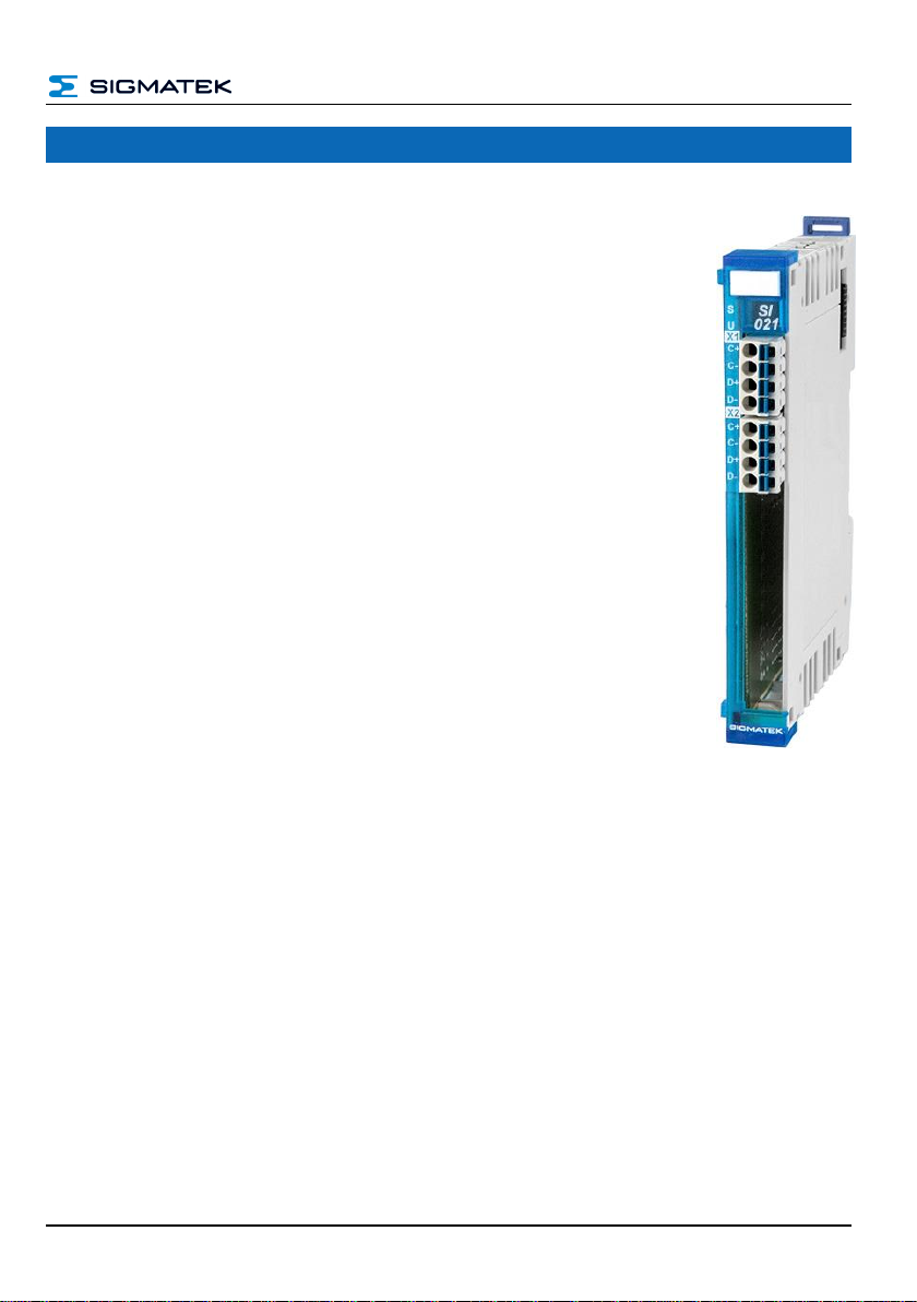
S-DIAS SSI INTERFACE MODULE SI 021
26.07.2023 Page 3
7.1 Status LEDs.................................................................................18
7.2 Applicable Connectors...............................................................18
7.3 Label Field...................................................................................19
8Wiring.....................................................................................20
8.1 Wiring Example...........................................................................20
8.2 Note..............................................................................................21
8.3 RS422 Interface...........................................................................21
9Function.................................................................................22
9.1 SSI Absolute Value Encoder Coding........................................22
9.1.1 Binary Mode...................................................................................... 22
9.1.2 Gray Code Decoder Mode................................................................ 22
10 Assembly/Installation ...........................................................23
10.1 Check Contents of Delivery.......................................................23
10.2 Mounting......................................................................................24
11 Addressing.............................................................................26
12 Supported Cycle Times ........................................................28
12.1 Cycle Times below 1 ms (in µs).................................................28
12.2 Cycle Times equal to or higher than 1 ms (in ms)...................28
13 Hardware Class SI021...........................................................29
13.1 General Information....................................................................30
13.2 Channel 1, 2.................................................................................31