Audient ASP8024 HERITAGE EDITION User manual

2
Welcome to your new
Audient ASP8024-HE

3
Contents
4
2
5
6
6
8
10
11
11
12
13
14
1513
16
17
18
19
20
2119
22
2321
24
25
26
27
28
29
30
31
36
37
38
38
39
39
39
39
40
40
41
41
41
41
42
42
43
43
2
44
45
52
53
54
55
55
56
57
58
59
62
68
Introduction Part 2: Using ASP4816-HE
Overview
Part 1: Console Functions
How to use this Manual
Console Layout
Unpacking
Input Module
Introduction
Inline Architecture
Tracking
Mixing
Master Module
Connector Panels
Power Supply
Service and Repair
Mic & Line Inputs
Routing and Auxiliaries
Equaliser
Short Fader (SF)
Long Fader (LF)
Stereo EFX Inputs
Master Fadar
Bus Trims & Aux Masters
Control Room
Sub Groups
Cue & Aux Masters
Live Room & Foldback
Heritage Output Card
Communications
Bus Compressor
Master Meters
Oscillator & Solo
Part 4: Further Information
Part 5: DLC Manual
Part 3: Optional Extras
& Modules
Getting Started
Capturing Your Final Mix
The Multi-Track Buses
Patchbay
Warranty
DLC Module*
Registration
Monitoring Recorded Tracks
Producer’s Desk
Console Specifications
Foldback
48 Channel Bus Mod & DFA
Glossary
Tracking with Eects
Cable Entry Meter Pod
VESA Screen Mount
Audio from DAW to Console
Sub Groups
Adding EQ to Track
Inserts and Auxiliaries (Outboard)
The Mix Bus
Adding Mix Bus Compression
* DAW specific manuals available online.

4
Introduction

5
With the ASP8024 in production for nearly 20 years, and thousands of consoles in use around the
world based upon David Dearden’s legendary circuit blocks, we’ve returned to his roots to release
the definitive version of the ASP8024 - the Heritage Edition.
Nineteen years ago David set out to design an analogue recording console not knowing it was
destined to become a modern classic. To commemorate Audient and David’s phenomenal
achievement we have re-imagined his timeless design with new enhancements, features and
tonal options based on his early years as a studio technician in the renowned Advision Studios,
London UK.
We have taken a great deal of pride and care in the design and manufacture of your ASP8024-HE
console with the aim of providing you with consistent and reliable performance for many years to
come.
How to use this manual
This manual has been divided into sections for your convenience.
The first section introduces ASP8024-HE and provides an overview of the control surface and
where to find things. The following sections provide detailed information regarding each function,
operation of controls and how they relate to each other. Along the way a number of handy tips
and suggestions will oer up possible uses and applications for the console during creative use.

6
Unpacking
Your Audient ASP8024-HE console has been carefully and meticulously tested and inspected
before dispatch. Please check for any signs of transit damage. If any signs of mishandling are
found please notify the carrier and inform your dealer immediately. The packaging should include
the console, an IEC power cord and this manual.
Important Safety Instructions
Please read all of these instructions and save them for later reference before connecting ASP8024-
HE to the mains and powering up the console. To prevent electrical shock and fire hazard follow
all warnings and instructions marked on the ASP8024-HE. This unit is connected via its IEC power
cord to the mains safety earth.
NEVER OPERATE THIS CONSOLE WITH THIS EARTH CONNECTION REMOVED.
Please read all of these instructions and save them for later reference before attempting to connect
the ASP8120 Ultra PSU to the Mains AC power source. To prevent electrical shock and fire hazard,
follow all the warnings and instructions marked on the rear of the ASP8120 Ultra PSU.
• This unit is connected via its power cord to the mains safety earth.
• NEVER OPERATE THE UNIT WITH THIS EARTH CONNECTION REMOVED .
• Check that the correct operating voltage has been set for your AC mains supply (115V for USA /
Japan or 230V for EU / UK etc.)
• Check that the fuse fitted is the correct type for the selected mains voltage.
• Always replace fuse with the correct type - 115V = T16A, 230V = T8A SLOW BLOW (time delay)
types.
• Ensure that the ASP8120 Ultra is firmly connected to the console multi-pin HIROSE connector
before powering on for the first time.
Do NOT attempt to tamper with the power supply or mains voltages
- HAZARDOUS TO HEALTH.
Always replace the mains fuse with the correct value - T2A slow blow.
!WARNING!
TO REDUCE RISK OF FIRE OR ELECTRIC SHOCK,
DO NOT EXPOSE THIS APPARATUS TO
RAIN OR MOISTURE.
PLEASE REFER SERVICING TO QUALIFIED SERVICE
PERSONNEL.
7
Service and Repair
The console uses a complex internal pcb sandwich arrangement making field service only
possible by a qualified technician. If any technical issues do arise with your console, please
contact your dealer as soon as possible to arrange for technical support. Do not attempt to
fix the console unless qualified to do so. See the warranty section provided at the end of this
manual for details of your cover.

8
Overview

9
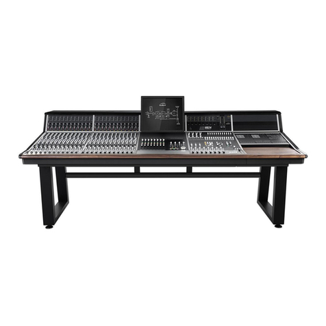
The ASP8024 Heritage Edition is a semi-modular, inline console, built to order and lovingly
constructed in our Hampshire factory by a skilled team who’ve hand-assembled these consoles
for nearly 20 years.
The ASP8024 Heritage Edition largely features the same smooth, clean sound as the original
Audient console design with its 24 Buses, 12 Auxes and 2 Cue Sends. However, we have made
several key enhancements including John HardyTM 990C summing amplifiers, as well as the
RETRO IRON Output Card, oering tonal options on your Mix Output.
The ASP8024-HE is a fully inline console allowing you to start building your mixes as you’re tracking.
By utilising the Long and Short Faders simultaneously you can create separate record and monitor
balances on the same channel strip, all while being able access the consoles split-able EQ and
Aux Sends.
Heritage Edition’s inline architecture reduces the consoles footprint while still providing incredible
audio performance, complete flexibility, intuitive workflow options, as well as being a visually
stunning centrepiece for your studio.
Modular design
As the ASP8024-HE is a semi modular console, there are various optional modules and extras
available. These are specified when ordering: Dual Layer Control, Patchbay, Producers Desk, VESA
Screen Mount, 48 Bus Mod and Cable Entry Pod.
This part of the manual will take you through the functionality of each section and individual
controls on the console. We recommend referencing the following pages when you are unsure
on how to use a feature or parameter, or would simply like to further understand specific controls
found on the console.

10
Console Functions
Part 1

11
Console Layout
Channel Inputs
BUS Routing Matrix
AUX & CUE Sends
Channel EQ
Short Fader
Long Fader
DLC VCA & HUI™
VESA POD
Monitoring
Aux Master
Blank POD
On-Board Patchbay
Master Meters
T/B Mic XLR
BUS Trims
BUS Trims
Sub-Group/Line I/P
Compressor
PSU Status
DLC DAW Transport Foldback & Comms
Sub-Group Faders
Mix Processing
Talkback
Mix Fader
Script Tray
DLC Module HUITM Control
& VCA Automation
Input Meters
Oscillator

12
Input Module

13
Mic & Line Inputs
The preamps of the ASP8024-HE use a
transformerless, eight transistor design to provide
a fast, clean sound with a little bit of colour when
pushed. An insert on both the mic and tape
inputs allows you to insert outboard gear into the
recording path or the playback / mix path.
1 METERS. The Meters show the level coming into
both the Mic/Line Input and the DAW/Tape Returns
enabling you to set a healthy signal level. They are
scaled in dBu.
2 INSERT ACTIVE. Activates the Insert for DAW/Tape
Returns, allowing you to add outboard gear into
your mixing path
3 Tape/Daw Trim. The Trim boosts or cuts the overall
level of the DAW/Tape Returns by ±15dB. Use to
gain stage input signals.
4 LINE. The Line Button swaps between the Mic and
Line Inputs.
5 MTR FLIP. Flips the source of the meters. By default
the large meter shows the DAW/Tape return and
the small meter shows the Mic/Line input.
6 INSERT ACTIVE. Activates the insert for the Mic/
Line Input.
7 GAIN. Applies gain to the Mic/Line Input to amplify
the signal. 6 to 60dB on Mic and -14 to 40dB on
Line.
8 Ø POLARITY REVERSE. Inverts the signal in the Mic/
Line Input. Useful if you are recording with multiple
microphones which may be out of phase with each
other.
9 48V. Turns on +48V Phantom Power locally for each
channel to power your microphones when needed.
10 HPF. Turns on the High Pass Filter to remove
frequencies below 75Hz in the Mic/Line signal.
2
1
3
4
6
5
78
810

14
1 BUS ROUTING SWITCHES. Assign channel signal
to any of the 24 Multi-track Buses (or 48 Buses if
the 48 Channel Bus Mod is installed)
2 SHIFT. Oset the value of each routing switch by 12
so that signals can access Multi-track buses 13-24.
3 FOLLOW PAN. Use to create a stereo bus. Bus
routing will follow the channel pan position, with
odd buses providing the left channel, and even
buses providing the right.
4 LF. Allows you to route audio from the Long Fader
path of the channel to the multi-track buses. By
default SF (Short Fader) signals feeds the routing
matrix.
5 SEND LEVEL (dB). Controls the amount of signal
being sent to the corresponding Aux/Cue Bus. This
can be anywhere from -inf to 0dB. Use these to
build FX sends to reverbs etc.
6 SF. By default the sends are taken from the LF (Long
Fader). SF allows you to send audio from the short
fader path to the Aux Buses. This can be pre or post.
7 PRE. Takes the signal from before the fader (SF
or LF) rather than after, to ensure that the fader
position doesn’t aect the aux send level. Great
for headphone mixes.
8 7-8, 9-10, 11-12. Use these buttons to shift the send
destinations to Auxes 7-12.
Routing and Auxiliaries
The routing of the ASP8024-HE allows you to send
the signal of any given channel to any of the 24 Multi-
track Buses, giving you a huge amount of flexibility at
both the tracking and mixing stage. Up to 12 Auxes
and 2 Cue Sends allow you to easily utilise outboard
eects and control over artist foldback.
1
24
6
3
5
8
7

15
Equaliser
Shelves
Parametrics
ASP8024-HE features the classic David Dearden
4-Band console Equaliser on every channel.
Oering two dual-band equalisers that can be
split individually to the Short (SF) or Long (LF) Fader
paths.
1 IN switches the Shelf EQ into the signal path.
2 SF switches the Shelf EQ to the short fader path
(independent of Parametric EQ).
3 AIR allows the frequency of the HF equaliser to
be selected.
4 100Hz allows the frequency of the LF equaliser
to be selected.
5 dB Knobs allow you to boost or cut each frquency.
6 IN switches the Parametric EQ into the signal
path.
7 SF switches the Parametric EQ to the short fader
path (independent of Shelf EQ).
8 kHz/Hz controls the centre frquency of the EQ
Band.
9 BW (bandwidth) Stands for bandwidth and
controls the how wide the frequencies around
the centre frequency. Choose a narrow BW for
surgical cuts or a wide one for more musical
boosts and cuts.
10 dB Knobs allow you to boost or cut each frquency.
1
3
2
4
6
5
7
9
8
10
5

16
Short Fader (SF)
ASP8024-HE is an inline console. This means that
there are both input and monitoring signal paths
on the same channel. By default, the Short Fader
contains the input signal, however you can use the
channel flip switch to switch to the tape signal.
Don’t forget that you can assign the Aux/Cue Sends
and EQ to the Short Faders by pressing the SF buttons.
1 Copy LF selects the post fader LF signal as the input
to the Short Fader path, overriding the Mic orTape
selection from the Flip Switch. This can be used to
ride the level of the Aux Sends on the Short Fader
(great for delay and reverb throws).
2 PAN places the signal in the stereo field by
balancing the signal between the left and right
channels.
3 MIX routes the SF signal to the stereo mix bus. It is
good practice to unroute any channels which are
not needed. This will reduce mix amp noise.
4 This is the SHORT FADER which controls the level
of the SF signal.
5 SOLO Mutes every channel except channels that
are soloed.
6 CUT will cut the Short Fader output of that particular
channel.
1
3
2
4
6
5

17
Long Fader (LF)
The Long Fader operates on the LF signal path and
is mainly used for creating the monitor mix and the
final stereo mix.
The fader is expected to operate around the 0dB
mark with 10dB of gain in hand, allowing the signal to
be increased or decreased in level.
When setting levels, start with the fader at the 0dB
position, then adjust the input sensitivity control to the
correct level.
1 CH Flip will flip the channel path onto the Long
Fader and the playback path onto the Short Fader.
2 PAN places the signal in the stereo field by
balancing the signal between the left and right
channels.
3 MIX. Pressing this button sends this channel to the
mix bus. To minimise the noise floor of the console,
this should be disengaged if the channel is not in
use.
4 SOLO Mutes every channel except channels that
are soloed.
5 CUT will cut the Short Fader output of that particular
channel.
6 FADER controls the amount of signal being sent
out of the Long Fader path.
6
2
4
1
5
3

18
Master Module

19
Stereo EFX Inputs
The Stereo EFX Inputs allow stereo signals to be
brought back into the console from an eect unit
without using up a complete channel strip.
Often stereo signals can only be routed to the stereo
mix, however, the ASP8024-HE stereo inputs allow
routing back to the Multi-track in addition to the mix.
5
4
3
2
1
7 8
6
1 BUS ROUTING allows you to send the stereo inputs
to any of the Multi-track Buses. This is done in pairs
as the stereo signal takes up 2 buses.
2 SHIFT switches the functions of the routing switches
from the first 12 Multi-track Buses to the second 12
Multi- track Buses.
3 F/B 1 & 2 controls the signal sends to Foldback
Output 1 and Foldback Output 2.
4 INPUT TRIM reduces or increases the signal level
of the stereo EFX Input from -20dB to +20dB.
5 FADER a fader in disguise as a knob, which controls
the level being sent to the Mix Bus if the Mix Button
is engaged.
6 MIX sends the channel to the Mix Bus. To minimise
the noise floor of the console, this should be
disengaged if the channel is not in use.
7 SOLO mutes every channel except channels that
are soloed.
8 CUT is used to mute the sound output of that
particular Stereo EFX Input.

20
Bus Master Trim
The Bus Master Trims are the final stage of level control
over the signals routed to the Multi-track Bus outputs.
Each Bus has a Level Trim although for the purposes of
this manual only a few are shown in the accompanying
diagram.
1
1 dB KNOB allows you to adjust the overall level of
a particular Multi-track Bus from -10dB to +10dB.
This manual suits for next models
1
Table of contents
Other Audient Recording Equipment manuals

Audient
Audient iD44 User manual

Audient
Audient iD24 User manual

Audient
Audient iD44 User manual

Audient
Audient iD4 User manual

Audient
Audient EVO 4 User manual

Audient
Audient iD4 User manual

Audient
Audient iD4 User manual

Audient
Audient iD4 User manual

Audient
Audient ASP500 Series User manual

Audient
Audient ASP8024 Dual Layer Control User manual