Nex-tech DTW Series User manual

DTW Series User’s Manual
S.I. Instruments
256 South Rd. Hilton
South Australia 5033
Ph (08) 8352 5511
www.si-instruments.com.au

2
Table of Contents
Table of Contents………………………………………………………… 2
Introduction………………………………………………………………… 3
Before Use………………………………………………………. 3
Operation Overview………………………………………… 3
Powering the DTW……………………………………………………….. 4
Charging the Batteries……………………………………. 4
Using the DTW…………………………………………………………….. 5
Powering up…………………………………………………….. 5
Basic Functions………………………………………………… 6
Main Menus……………………………………………………… 8
SETUP………………………………………………….. 8
AUTO-OFF……………………………….. 9
AUTO-RESET……………………………. 9
PASS-FAIL……………………………….. 10
RS 232 OPTION………………………. 12
LOAD DEFAULT………………………… 13
CALIBRATION………………………………………. 13
DIAGNOSTIC………………………………………… 13
ABOUT………………………………………………….. 14
DTW Specifications………………………………………………………. 16
Conversion Factor……………………………………………………….. 17

3
Introduction
Thank you for choosing the DTW series instrument. With correct
use and regular re-calibration it will give many years of accurate and
reliable service.
The DTW can measure Clock-wise and Anti Clock-wise Torques
accurately, while being simple to use by the operator.
Nextech offers software and accessories to make your gauge
more. Ask your Nextech distributor for additional information or visit our
website at www.forcetorque.com
Before Use
Upon receiving the unit please check that no physical damage
has occurred to the packaging material, plastic case or the instrument
itself. If any damage is evident please notify Nextech immediately.
Operation Overview
The most commonly used features (such as displaying torque,
peak hold, zero and changing of displayed units) can all be done by
pressing a single dedicated key identified on the font panel-see the Basic
Functions section.
You can press a menu key to access the DTW configuration- see
the Main Menu section.

4
Powering the DTW for the first time
The DTW is supplied with a set of 6 Nickel Metal Hydride AAA
rechargeable batteries pack. For safety reasons during transportation the
batteries are shipped discharged. To obtain maximum battery life we
recommend that you charge them with the charger/adaptor supplied for
at least 14-16 hours when you first receive the instrument. Only use the
adaptor/charger supplied.
Battery Indicator
Battery level > 7.2 V
7.2 V > Battery level > 7.0 V
7.0 V > Battery level > 6.55 V
6.55 V > Battery level > 6.1 V
Battery level < 6.1 V
If battery level less than 6.0 V , The “battery empty” massage
will be displayed and the DTW will be powered down automatically.

5
Using the DTW
Powering up
As show in Figure 1 the control panel has eight keys.
Figure 1 DTW control panel
To power up the DTW press the ON/OFF key. A short self-test
runs during which the display will show the capacity in Nm.
After the self test, providing no load has been applied to the
instrument, the display will show all zeroes. This is because the DTW
rezeroes itself during the self-test routine.
If a Torque is applied via the Torque Transducer the reading on
display will register the applied torque.
Torques may not show zero if it is moved during the self test routine.
Once it is properly mounted and zeroed the reading will be stable.
*Do not overload the Transducer. This will cause irreparable
damage. Torques greater than 120% of full-scale will produce an audible
beep and OVERLOAD massage will blink on the display until load is
release and RESET key is pressed.
To power down the DTW press the ON/OFF key.
All the current settings are saved when the DTW is turned off and the
DTW will function in the same mode when powered up again.
6
Basic Functions
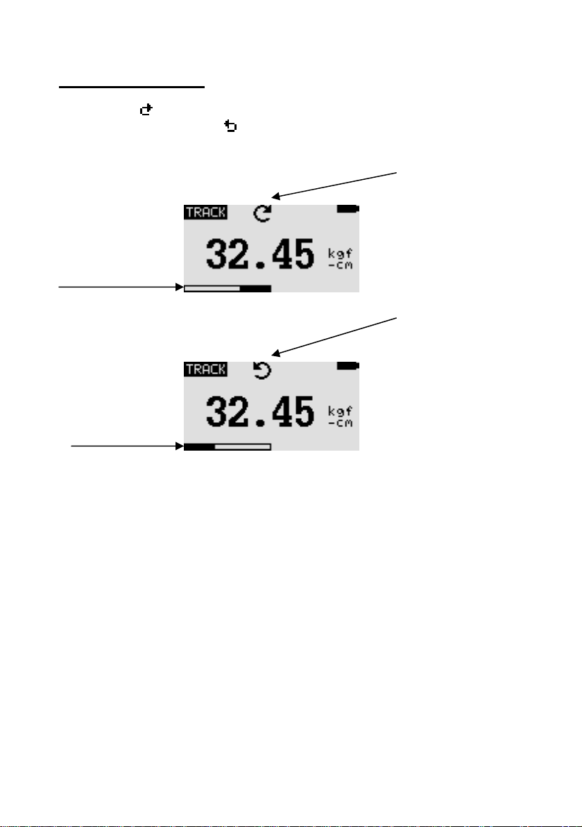
Clock-wise torque are displayed on the DTW and recognized by
the symbol . Anti Clock-wise torque are displayed on the DTW and
recognized by the symbol .
Display of Clockwise/Anti-Clockwise
Clockwise
symbol
Load indicator
bar of Clockwise
Anti-Clockwise
Symbol
Load indicator
bar of Anti-
clockwise
Figure 2 Clockwise and Anti-Clockwise displays
A load indicator bar alerts the operator to how much load has been
applied to the Transducer.
For Clock-wise torques the indicator bar move from right to left. For Anti
Clock-wise torques the indicator bar move from left to right.
Zeroing the DTW During the operation of the DTW it is often necessary
to zero the display – e.g. when you wish to tare out the torques, so it
does not become part of the measured reading. Press and release the
ZERO key.
Changing the unit of measure You can choose from the following
units of measure: N.m, kgf.cm, kgf.m, in.lbs and ft.lbs. To change the
display units press the UNITS key. Each successive key press will select
the next available units until the DTW returns to its original setting. The

7
DTW automatically converts readings as new unit of measure are
selected.
Changing the mode of measure You can choose from the following
modes of measure: Track, Peak and First Peak.
To change the display modes press MODES key. Each successive
key press will select the next available modes until the DTW returns to
its original setting.
Track mode The display will now indicate Torque applied in
both directions as they are applied to the Transducer and maintain the
live display. See Figure 3a
Track symbol
Figure 3a Track
Peak-mode The display will show the maximum torque in both
direction. See Figure 3b
Peak symbol
Figure 3b Peak
First Peak mode The display will show the First peak torque in
both direction. See Figure 3c
F-Peak symbol
Figure 3c F-Peak

8
Resetting the DTW Press RESET key to clear both maximum registers
and prepare for detecting the next maximum readings.
Backlit Display When you press any key or applied torques to
Transducer greater then 0.5 % of full scale the backlight will go on for 6
seconds.
Send reading to PC Any reading can be send to PC or thermal printer
any time by press PRINT key.
Main Menu
Press MENU/ESC key to access the main menu. To move
between the option listed on the main menu page, press UP and DOWN
arrow keys to move the cursor. Press ENTER to select the sub-menus,
activate feature and enter values. Within sub-menus UP, DOWN LEFT
and RIGHT arrow keys will also change numerical values. Press ESC to
return to the main menu page.
MAIN MENU
1) SETUP
2) CALIBRATION
3) DIAGNOSTIC
4) ABOUT
Figure 4 Main Menu
1) SETUP Press the MENU key, the display will show main menu page
and use UP and DOWN to move the cursor point to SETUP. Press the
ENTER key. The display will show the setup menu page. Press ESC key to
return to the main menu page.
SETUP MENU
1) AUTO-OFF
2) AUTO-RESET
3) PASS-FAIL
4) RS232 OPTION
5) LOAD DEFAULT
Figure 5 Setup Menu

9
1.1) AUTO-OFF An Auto-off feature can be enabled to
conserve battery power where the DTW powers down after 5,10 and 15
minutes (depend on Auto-off time) since the last key press. The auto-off
symbol will appear in the main display if you activate this feature.
To access AUTO-OFF menu, Press UP and DOWN to move the
cursor point to AUTO-OFF and press the ENTER key the display will show
the auto-off menu page. Press ESC key to return the setup menu page.
AUTO-OFF MENU
1) OFF
2) 5 MINUTE
3) 10 MINUTE
4) 15 MINUTE
Figure 6 Auto-Off Menu
Use UP and DOWN key to move the cursor. Press the ENTER key
to select auto-off option and return to setup menu page.
1.2) AUTO RESET the Auto reset feature used to set the auto
clear level. This mode works when the reading value is higher than
setting value, causing the peak value to change to a new held value. The
user does not need to press RESET key, since the peak value will
automatically reset. The Auto-Reset symbol will appear in the main
display if you activate this feature.
To set AUTO RESET, Press UP and DOWN to move the cursor
point to AUTO RESET and press ENTER key The display will show the Set
Auto reset menu page. Press ESC key to return the main menu page.
AUTO-RESET MENU
AUTO-RESET = 10.000
UNIT = kgf-cm
“Zero key to reset”
Figure 7 Auto-Reset Menu
Use UP and DOWN keys to change the value, press and hold to
scroll values. When the correct value is reached press ENTER to set NEW
VALUE and return to main menu page. Use UNIT keys to change the unit.

10
*Auto Reset feature will automatically disabled if you set
AUTO RESET = 0.
1.3) PASS-FAIL the Pass-Fail feature used to set a defined
acceptable maximum and minimum torques gap for measuring. It
activate by setting the lower level and upper level torques limit If the
torques value is within the gap level, the display will show message
PASS. Any reading values outside this gap (higher or lower), the display
will show message FAIL. If you activate this feature the Pass-Fail symbol
will display on main display.
To access PASS-FAIL menu, Press UP and DOWN to move the
cursor point to PASS-FAIL and press the ENTER key the display will show
the Pass-Fail menu page. Press ESC key to return the setup menu page.
PASS FAIL MENU
UPPER = 2.5
LOWER = 1.0
Unit = kgf-cm
“Zero key to reset”
Figure 8 Pass-Fail Menu
Use LEFT ARROW keys to move cursor point to the desired value.
Use UP and DOWN keys to change the value, press and hold to scroll
values. Use RIGHT ARROW key to change the unit. Press ENTER to save
setting and return to Setup menu page.
*Pass-Fail feature will automatically disabled if you set
LOWER and UPPER = 0. *LOWER must be less than the UPPER.
example LOWER LEVEL = 0 Nm, UPPER LEVEL = 20 Nm
Load
The display will show FAIL.
Upper level
The display will show PASS.
Time

11
example LOWER LEVEL = 20 Nm, UPPER LEVEL = 0 Nm
Load
The display will show PASS.
Lower level
The display will show FAIL.
Time
example LOWER LEVEL = 10 N, UPPER LEVEL = 20 N
Load
The display will show FAIL.
Upper level
The display will show PASS.
Lower level
The display will show FAIL.
Time
1.4) RS232 OUTPUT This use to set option of RS232 output for
send the measurements value to PC or Thermal printer. Setting =
38400,N,8,1.
RS232 OPTION MENU
1) MANUAL
2) AUTOMATIC
Figure 9 RS232 Option Menu

12
1.4.1) MANUAL If you selected this option, the measurement
value send to rs232 output port by press ENTER key.
1.4.2) AUTOMATIC If you selected this option, the
measurement value send to rs232 output port every 125 mS in TRACK
mode and after the peak or first peak value is occur in PEAK or FPEAK
mode.
Data format :
Track mode = Track_SVVVVVV_UUUUUU_MMMMMM(cr)(lf)(cr)
Peak mode = _Peak_SVVVVVV_UUUUUU_MMMMMM(cr)(lf)(cr)
Fpeak mode = Fpeak_SVVVVVV_UUUUUU_MMMMMM(cr)(lf)(cr)
Where : _ = Space U = Unit of measurement
S = Sign of value M = Sensor model name
V = Value
example Measurements value = 10.05 in-lbf, model = DTW010
Track mode = Track_+__10.05_in-lbf_DTW010 (13)(10)(13)
Peak mode = _Peak_+__10.05_in-lbf_DTW010 (13)(10)(13)
Fpeak mode = Fpeak_+__10.05_in-lbf_DTW010 (13)(10)(13)
example Measurements value =125.05 ft-lbf, Sensor model = DTW100
Track mode = Track_+125.05_ft-lbf_DTW100 (13)(10)(13)
Peak mode = _Peak_+125.05_ft-lbf_DTW100 (13)(10)(13)
Fpeak mode = Fpeak_+125.05_ft-lbf_DTW100 (13)(10)(13)
1.5) LOAD DEFAULT The DTW may be returned to its original
factory default setting.
To set factory default, Press UP and DOWN to move the cursor
point to LOAD DEFAULT and press ENTER key the display will show Load
Default menu page. Press ESC key to return to the setup menu page.
LOAD DEFAULT
AUTO-OFF = OFF
AUTO-RESET = OFF
PASS-FAIL = OFF
RS232 = MANUAL
Figure 10 Load default Menu

13
Press ENTER key to Load default setting and return to setup
menu page.
2) CALIBRATION This is used by service technicians when calibrating
the DTW. Contract your Dillon distributor for details.
3) DIAGNOSTIC This use to check status of the Transducer. If you
suspect that your transducer has sustained an overload it is possible to
check the status of the Transducer immediately.
Go to main menu page. Use UP and DOWN key to move the
cursor point to DIAGNOSTIC and press ENTER key the display will show
Diagnostic menu page. Press ESC to return to main menu page.
DIAGNOSTIC
OVERLOAD COUNT: 10
ORG. OFFSET : +0.4 %
CUR. OFFSET : +0.4 %
Figure 11 Diagnostic Menu
OVERLOAD COUNT = Total overload count.
ORG.OFFSET = % offset when last calibrate.
CUR.OFFSET = % current offset
If the % offset is between 5% - 10 % please contact your
supplier to arrange a recalibration of your gauge.
If the % offset is greater than 10% please contact your supplier
to arrange for Transducer replacement.
These values are given as an indicator only – the need for
calibration/repair may vary according to the individual characteristics of
the Transducer.
4) ABOUT This shows the information of your DTW (Firmware revision,
Model, Capacity, Serial number). To access ABOUT menu, Go to main
menu page and press UP and DOWN to move the cursor point to
ABOUT and press ENTER key the display will show About menu page.
Press ESC key to return to main menu page.

14
ABOUT
FIRMWARE REV. : 1.05
MODEL: DTW
CAPACITY: 100N
S/N: 05350001
Figure 12 About Menu
WARNING !
1) Overloading the transducer does not only damage the
transducer but may break the transducer head and could result in
injury!
2) The transducer must be fastening properly by 4 bolts
and nut to the work surface, either horizontally or vertically.
Failing to do so may result in damage to the transducer and could
result in injury to the operator.
3) Ensure that torque wrench’s driver has engaged the
transducer socket properly when operating. The transducer head
may be damaged if not engaged properly and could result in
injury to the operator.
4) Please make sure that you have safety gear and safety
measure when applying torque to the transducer and when
calibrating the transducer.
5) Do not use charger other than supplied with unit or
recommended for replacement. Using a wrong charger may
result in overload and explosion or Ni-MH rechargeable battery
inside the monitor.
15
Torque Wrench Testing
Specifications
Environment:
Operating condition: For indoor use only.
Operating temperature: 0 °C to 50 °C.
Storage temperature: -15 °C to 65 °C.
Humidity: Maximum 70% Relative.
Accuracy
Accuracy(Combined error): ± 0.5 % of full-scale.
Creep: ± 0.02 % of full-scale.
Non-Linearity: ± 0.02 % of full-scale.
Temperature shift at zero load: ± 0.02 % of full-scale/ºC.
Dimension & Weight
Size: 6 x 16.3 10.8 c.m.
Weight: 2.8kg.
Mechanical Rating
Maximum torque: 120% of rated capacity stated.
Maximum mounting torque: 150% of rated capacity.
Electrical:
Charger rating: 500mA 12 Volts DC.
Charging Time: 4-6 Hours for full charge.

16
ADC Sampling Rate: 2,000 Hz
Peak Capture Rate: 0.010 S.
Output RS232C: PS2 Connector, 8 Data bits,
1 Start bit, 1 Stop bit, no parity,
38400 baud rate.
Display: 128x64 pixel dot matrix display.
Unit of measurement: N.m, kgf.cm, kgf.m, in.lbs, ft.lbs
Mode of measurement: Track, Peak, First-Peak.
Minimum torque: Readable at min 5% of F.S
Auto Reset Range: Adjustable 2 to 100% of F.S
Pass-Fail Range: Adjustable 2 to 100% of F.S
Conversion Factor:
Unit N-m kgf-cm kgf-m in-lbf ft-lbf
N-m 1 10.197 0.10197 8.8507 0.73756
kgf-cm 0.0980665 1 0.01 0.86796 0.07233
kgf-m 9.80665 100 1 86.796 7.233
in-lbf 0.11298 1.152 0.01152 1 0.08333
ft-lbf 1.3558 13.8255 0.138255 12 1
Capacity and Divisions
MODEL N - m kgf - cm kgf- m lbf - in lbf - ft
DTW 0.5 0.5 x 0.0001 5.099 x 0.001 0.0509 x 0.0001 4.425 x 0.001 0.3687 x 0.0001
DTW 1 1 x 0.0002 10 x 0.002 0.1020 x 0.0002 8.850 x 0.002 0.7375 x 0.0002
DTW 5 5 x 0.001 50.99 x 0.01 0.5099 x 0.1 44.25 x 0.01 3.687 x 0.001
DTW 10 10 x 0.002 102 x 0.02 1.02 x 0.0002 88.50 x 0.02 7.375 x 0.002
DTW 25 25 x 0.005 255 x 0.05 2.55 x 0.0005 221.3 x 0.05 18.44 x 0.005
DTW 50 50 x 0.01 509.9 x 0.1 5.099 x 0.001 442.5 x 0.1 36.87 x 0.01
DTW 100 100 x 0.02 1020 x 0.2 10.2 x 0.0002 88.50 x 0.02 7.375 x 0.002
DTW 250 250 x 0.05 2550 x 0.5 25.5 x 0.005 2213 x 0.5 184.4 x 0.05
DTW 300 300 x 0.05 3060 x 0.5 30.60 x 0.005 2655 x 0.5 221.3 x 0.05
DTW 500 500 x 0.1 5099 x 1 50.99 x 0.01 4425 x 1 368.8 x 0.1
DTW 800 800 x 0.2 8158 x 2 81.58 x 0.02 7080 x 2 590 x 0.2
DTW 1000 1000 x 0.2 10200 x 2 102 x 0.02 8850 x 2 737.5 x 0.2
DTW 1500 1500 x 0.2 15296 x 2 152.96 x 0.02 13276 x 2 1106.3 x 0.2

17
UPDATE MANUFACTURING (THAILAND) CO.,LTD.
2 Soi Rama IX (Soi 21 Seri 4)
Suanluang, Suanluang
Bangkok 10250, Thailand
www.forcetorque.com
S.I. Instruments
256 South Rd. Hilton
South Australia 5033
Ph (08) 8352 5511
www.si-instruments.com.au
Table of contents


