MAINTENANCE MANUAL
ATC-601-2
APPENDIX G
Page 2
Jan 1/07
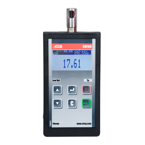
1. Front Panel
Refer to Appendix G, Figure 1.
ITEM DESCRIPTION
1. CHARGE Indicator
LED indicates the charger is active (ac applied with Test Set Off). Red indicates when
battery is charging and green indicates battery is more than 80% charged.
2. SYNC Connector (J10055)
BNC type connector provides Oscilloscope Sync. Long pulse goes from low to high
before an interrogation and from high to low before an expected reply.
3. COMM Connector (J10053)
LEMO type connector provides for remote 4-line serial communication (with Option 1
installed) and includes the signals TRANSMIT, RECEIVE, DTR and CTS. The COMM
Connector provides data dump output capability with or without Option 1 installed. Refer
to COMM Connector Pin-Out Table in Appendix A.
4. SETUP Key
Enters Setup Menus onto the DISPLAY.
5. FUSES
Provide safe operation with ac input power applied to the ATC-601. Refer to Appendix F
for correct fuse size and type.
6. SELF TEST Key
Enters Self Test screen onto the DISPLAY.
7. AC PWR Connector (J10050)
Provides the input for an external ac power source (100 to 120 VAC at 60 Hz or 220 to
240 VAC at 50 Hz) for recharging the battery or operating the Test Set. The operating
voltage range depends on the Line Supply Switch Setting, only serviceable by a qualified
technician. Refer to Battery/Voltage Instructions in the ATC-601-2 Operation Manual.
8. SLEW Keys
Used to:
OAdjust values and parameters in Setup Menus.
OSelect Signal Type in Diagnostics screen.
OAdjust values in Diagnostics screen.
OSelect antenna to be tested in Power Test.
Variable slew rates are available, depending on item being edited. Keeping SLEW Key
pressed provides greater rate of change, in most instances, than pressing and releasing.
9. RUN/STOP Key
Starts or stops testing.

