NEXIS PTZ10UH User manual

USB HD PTZ Camera
User Manual V1.0


SAFETY NOTES
Before installing the device, please read this manual carefully and follow instructions
indicated to ensure proper operation. Please keep this manual for future reference.
Before powering on the device, please check the input power voltage carefully, the camera
accepts DC5V, otherwise, it may cause damage to the camera.
Please put USB data cable, video and control cables at safe place in order not to cause
malfunction to the device.
Please put the device into use at required working temperature and humidity, working
condition of the device is 0℃~+40℃,humidity at<90﹪. Please avoid to have unrelated
objects get into the device like corrosive liquid that may cause damage / danger.
Please avoid shock, vibration, soaking may cause to the device when transporting and
installing, otherwise, it may cause damage to the camera.
Please only refer to authorized personnel to repair the device, do not disassemble the
camera by yourself.
Only use USB date cable and control cables, and the cables should be connected separately
in order to ensure proper use. Do not aim the camera lens at sunlight or strong lights that
may cause damage to the imaging system of the device.
Please use soft cloth to clean the device, do not use strong or abrasive detergent to clean
that will damage the device’s housing / lens.

Warnings
1.If you need to extend the power cable, please extend the power cable from the part on
below picture (220V/110V), do not extend from part 1 on below picture (DC12V), otherwise
it will cause unexpected damage to the device.
2.To prevent infringement of the rights of others, please confirm that it is installed and used
within the scope permitted by local law!

CONTENTS
PRODUCT OVERVIEW--------------------------------------------------------- 1
FEATURES -------------------------------------------------------------------------------- 1
PACKING LIST ----------------------------------------------------------------------------- 1
MAIN PARTS AND CONTROL INTERFACES ---------------------------------------------------- 1
REMOTE CONTROL------------------------------------------------------------------------- 3
INSTALLATION ---------------------------------------------------------------- 5
DESKTOP MOUNT INSTALLATION------------------------------------------------------------ 5
WALL MOUNT INSTALLATION --------------------------------------------------------------- 5
CABLE CONNECTING --------------------------------------------------------- 6
AMCAP CAPTURE SOFTWARE ----------------------------------------------- 7
DRIVER INSTALLATION OF USB VIRTUAL SERIAL PORT ------------------- 7
ANNEX 1 TECHNICAL SPECIFICATIONS-------------------------------------- 8
ANNEX 2 SIZE AND DIMENSION ---------------------------------------------- 9
TROUBLESHOOTING-------------------------------------------------------- 10


1
PRODUCT OVERVIEW
Features
Using the newest CMOS sensor, up to
1920x1080P30;
3X/10X optical zoom;
3X: Max FOV: 99.6°;
Support H.264, MJPEG compressed
video output, standard UVC protocol;
Power consumption <5W;
HDMI, USB output;
Advanced 2D/3D noise reduction
algorithm, excellent noise control;
Support USB and remote control to
control the camera;
DC servo motor drive, smooth operation,
accurate positioning;
Base with tripod thread interface for tripod
fixing;
Packing List
When you open the package, please make
sure below items are included. If any items
is missing, please contact your supplier.
PTZ Camera (1)
Power Adapter (1)
Remote Control (1)
USB Cable (1)
Software Disc (1)
2
Main Parts And Control
Interfaces
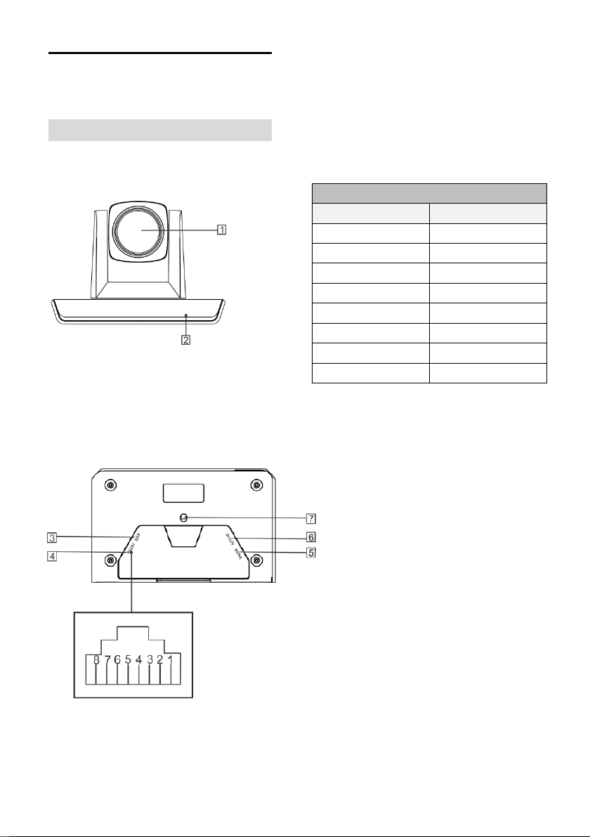
PTZ Camera
Front View
1 Camera Module
2 Power Indicator
Bottom View
3 USB
4 RS-232
5HDMI
6 Power(DC12V)
7Installation Hole
1/4” inch screw, used to fix the camera
Pin Definition Of Control Port
Pin No
Definition
1
/
2
/
3
RXD
4
GXD
5
/
6
TXD
7
/
8
/

3
Remote Control
1 HOME button
Press HOME button, camera moves to
initial position where both pan and tilt
angle is zero.
2 Camera Selection Button
Used to switch among 4 cameras, press
1-4 number buttons to control cameras
with 1-4 address respectively. For
example, press button 1 to control the
camera with address 1.
3 Focus
Camera does not support this feature.
4 Iris
Press“ ”button to reset brightness
value to default. “ ”button to increase
brightness, “ ”button to decrease
brightness.
5 Menu
Camera does not support this feature.
6 Data
Camera does not support this feature.
7 Number Keys
Used to input numbers, for example,
preset number.
8 Cancel
Used to delete number inputted.
9 Power
After the camera has been connected to
power source, press this button to turn on
/ off the camera.
10 Reserved Buttons(F1, F2, F3, F4)
These buttons are reserved for future use.
11 Pattern
Camera does not support this feature.
12 BLC
Used to open / close back light
compensation.

4
13 Zoom
Used to adjust zooming times.
“ ”button to zoom in
“ ”button to zoom out.
14 Back
Camera does not support this feature.
15 OK
Press this button to switch among pan / tilt
control speeds.
16 Direction Operation
Press these four buttons to pan left/right
and tilt up/down.
17 Preset Setting
“ ” button to call a preset.
Input number key(s), and then press this
button to call a preset.
“ ”button to set a preset.
Move the camera to a specific position,
adjust focus value and etc., and then
press this button to set a preset.
“ ”button to clear a preset.
Input number key(s), and then press this
button to clear a preset.
18 Enter
After inputting numbers, press this button
to confirm.

5
INSTALLATION
The camera has 2 installation types:
desktop, wall (optional) installations.
Desktop Mount Installation
1. Put the camera on a flat surface. In
case the camera has to be placed on an
inclined surface, make sure the cline
angle is less than 15 degrees to ensure
proper pan /tilt operation.
Wall Mount Installation
(optional )
1. According to diameter and position of
the 2 installation holes (As shown below)
on the bracket, drill 2 holes on the wall
and fix the bracket.
2. Before fixing the camera, set the DIP
switches of the camera correctly.
3. Use inch screws to fix the camera on
the bracket, fix the limitscrew .According
to actual requirement, and make sure
the camera is tightly fixed onto the
bracket before your hands leave the
camera.
Note
Take effective measures to avoid camera
from dropping.
Do not grab the camera head when
carrying.
Do not rotate the camera head with
hand. It may cause malfunction to the
camera.
Note
Make sure the installed place is strong
and safe enough to hold the camera and
relative parts, it is suggested that the
installed place can withstand 4 times the
weight of the camera and its relative
parts
6
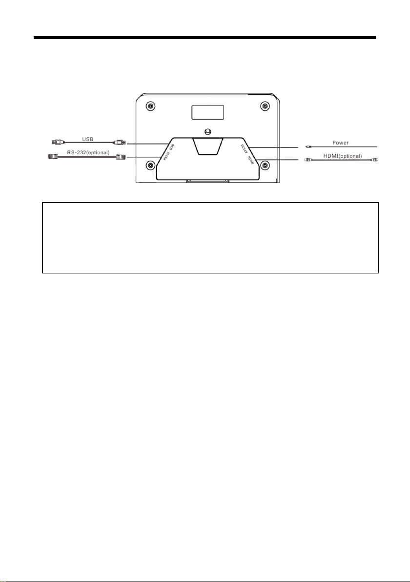
CABLE CONNECTING
Note
If preset 0 has been saved, after powered on, camera moves to preset 0 automatically; if
preset 0 has not been saved, after powered on, camera moves to Home position, where
both pan and tilt angle is zero and zooming time is 1x.
7
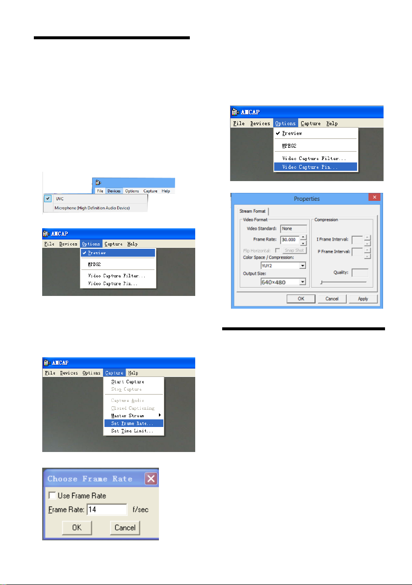
AMCAP CAPTURE
SOFTWARE
Open software, choose “USB”, from
“Options”, tick “Preview” to view camera
image.
If frame rate is not enough, go to
“Capture” / “Set Frame Rate” / “Use
Frame Rate” and disable it.
To change frame rate or resolution, go
to “Capture” / “Set Frame Rate” / “Use
Frame Rate” and change value
accordingly.
DRIVER INSTALLATION
OF USB VIRTUAL
SERIAL PORT
The camera supports one USB virtual serial
port at the same time, with which the
camera can be controlled via RS-232 cable.
Driver installation is required. Before
installation, the USB connection between
PC and the camera needs be removed.

8
ANNEX 1 TECHNICAL SPECIFICATIONS
VIDEO
Image Sensor
1/2.8” CMOS, 2.16megapixel
Optical Zoom
3X, f=3.35.-10.05mm, F1.7-F3.0
10X, f=5.15-47.38mm, F2.38
Field of View
99.6°-30.6°
62.2°-7.08°
Focus System
Auto, Manual, PTZ Trigger, One Push Trigger
Exposure Control
Auto/ Manual
White Balance
Auto, Manual, One Push Trigge, Auto Tracking
Min. illumination
0.5 lux (color), 0.1Lux (B/W)
Gain
Auto /Manual
Shutter Speed
1/25 to 1/10,000s
BLC
Support
DNR
2D/3D
S/N Rate
≥50dB
PTZ
Pan Angle
-90°~+90°
Tilt Angle
-30°~+90°
Pan Speed
15°/ S
Tilt Speed
10°/S
Preset Number
32
Interface
HDMI Port
1920x1080P30
Control Interface RS-232
IR Remote Control
Support
USB
Resolution
Max Support 1920*1080@30fps
Image Compression
H.264/MJPEG
UVC Protocol
USB2.0, UVC 1.0~UVC 1.4
UVC PTZ Control
Support
General
Power
DC12V
Power Consumption
<5W
Operating Temperature
0°C ~ + 40°C
Storage Temperature
-20°C~+60°C
Dimensions (W×D×H)
163 mm×101 mm×114mm
Weight
0.6KG
Body Color
Black

9
ANNEX 2 SIZE AND DIMENSION
Front Rear
Top Side
Bottom

10
TROUBLESHOOTING
Problem
Possible Cause
Solution
No action or image
after powered on,
No self-testing after
powered on, or with
motor noise
Power supply failure
Check power supply
USB cable failure
Replace USB cable
Use non-standard USB cable, the
cable is too long
Add an external power supply, or
add a USB HUB for external power
supply
Mechanical failure
Repair
Not controllable from
remote controller
Low battery of remote controller
Change battery for remote controller
Exceed remote control distance
Control within distance of 8M
After power on,
self-test
successfully, but not
controllable
Wrong address / protocol / baud rate
Check & set again
Wrong connection or open circuit of
RS-232 cable
Check & reconnect


The user manual is only for reference, it is subject to
changes, please ask for the latest version from your
supplier.
Table of contents
Popular Security Camera manuals by other brands


Novus
Novus 800 Series user manual

TRENDnet
TRENDnet TV-IP600 user guide

Honeywell Home
Honeywell Home SUMMER WAVES SKIMMERPLUS SFX600 Quick installation guide

Panasonic
Panasonic WV-CS570/G operating instructions

Illustra
Illustra Essential Gen4 quick start guide

Honeywell
Honeywell HDZP30XD4 quick start guide


