NexPower NT AF Series User manual

No. 2, Houke S. Rd., Houli Dist., Taichung City 421, Taiwan (R.O.C.)
Tel:886-4-25808888 Fax:886-4-25808899 http://www.nexpw.com
Installation Manual
Global version (A)
Frame Type PV Module
[For IEC]
NT-xxx AF / NT-xxx AX
[For UL]
NT-xxx UF / NT-xxx UX

Frame Type PV Module
Copyright © NexPower Technology Corp. ~1~
Table of Contents
1.Introduction .................................................................................2
1.1 Safety .................................................................................................... 2
1.1.1 General Safety..............................................................................................2
1.1.2 Handling Safety............................................................................................3
1.1.3 Installation Safety ........................................................................................3
1.2 Storage.................................................................................................. 5
1.3 WEEE Information................................................................................ 5
1.4 Disclaimer of Liability.......................................................................... 5
2.Installation ...................................................................................6
2.1 General Information............................................................................. 6
2.2 Mounting Method ................................................................................. 6
2.2.1 Bolting System.............................................................................................7
2.2.2 Clamping System.........................................................................................7
2.3 Wiring.................................................................................................... 9
2.3.1 Series Wiring .............................................................................................. 10
2.3.2 Parallel Wiring ............................................................................................10
2.4 Cable Selection .................................................................................. 11
2.5 Bypass Diodes ................................................................................... 11
2.6 Grounding........................................................................................... 11
2.7 Inverter Requirement......................................................................... 13
3.Maintenance...............................................................................14
3.1 Cleaning Instructions ........................................................................ 14
3.2 System Inspection ............................................................................. 14
APPENDIX 1 - Appearance.............................................................15
APPENDIX 2 - Mounting Guideline................................................16

Frame Type PV Module
Copyright © NexPower Technology Corp. ~2~
1.Introduction
Thank you for choosing NexPower PV Module (Photovoltaic Module). Please read this
manual carefully before the installation. It provides important safety and instructions for
installation and maintenance of this PV Module. Please refer to product specification for all
electrical and mechanical characteristics of the NexPower PV Module.
Failure to follow the requirements and instructions in this manual will invalidate the
warranty for PV Modules provided by NexPower.
1.1 Safety
Risk of electric shock Caution Prohibit
1.1.1 General Safety
PV module converts sunlight to electricity, when sunlight or light other source illuminates
the module surface. PV modules can produce high voltage and current which may cause serious
injury or even death. Extra attention is required to avoid “Electric Shocks” during usage.
Do NOT work under rain, snow, or windy conditions.
Please note, the back surface of PV module is not protected by glass and is vulnerable to
sharp objects.
Do NOT install PV module upside down (junction box downward).
Protect plug contacts against soiling and do NOT use soiled plug contacts to make any
plug connections.
Do NOT disassemble the PV module or remove any component or label from the module.
Do NOT drill holes in the frame or on the glass of PV module.
Do NOT artificially concentrate sunlight onto the PV module.

Frame Type PV Module
Copyright © NexPower Technology Corp. ~3~
Do NOT use chemicals in cleaning the surface or back sheet of PV module. Do NOT let
water remain on the glass surface of PV modules for an extended period of time.
Do NOT cover the water drain holes of the frame.
Do NOT hang or carry PV module by the cable.
Do NOT pull the cable, resulting in loose or damaged the junction box during handing and
installing process.
1.1.2 Handling Safety
The manual handling process must be made by two people. If the PV module damaged
(fault, crack or break) is caused by improper handling process, it will be deemed negligent
construction work.
Do NOT store or move the modules with the cables connected.
Do NOT use PV modules near equipments or locations where flammable gases can be
generated.
Do NOT stand or step on the PV module, cables, connectors, or end caps.
Do NOT drop the PV module or allow objects to fall on PV module.
1.1.3 Installation Safety
Always wear electrical insulating gloves, protective head gear, suitable eye protection, and
safety shoes while working on systems. Use only insulated tools during installation.
Do NOT touch the junction box or the output cables connectors with bare hands during
installation, regardless whether the PV module is connected to or disconnected from the system.
When connecting cables, push the plus and minus connectors against each other while
twisting them until they are fully engaged.
Mount the PV module onto the structure member with specified mounting structure. Make
sure to fasten bolts completely and lock in order not to loosen.

Frame Type PV Module
Copyright © NexPower Technology Corp. ~4~
The support structure for the PV module must be engineered to withstand the anticipated
wind and snow loads. Additionally, other forces may need to be considered according to local
standards and regulations.
Appropriate measures should be taken to prevent possible damage to lower edge of the
PV module in snow condition and also take proper steps to maintain reliability and safety, in case
the PV modules are installed in area such as cold areas/ strong wind areas.
The position of junction box should not overlap the mounting structure.
Junction box, cables and connectors should not be stressed in any circumstances.
The PV module can either be installed in portrait or landscape orientation (Fig. 1), however
portrait mounting is strongly recommended. Following conditions must be conformed during
design phase.
i) For all conditions, partial shading parallel to the longitudinal direction is not permissible.
Even in case of on-end assembly all shading parallel to the longitudinal direction must be
avoided at all times especially during completion of installation when the modules are
hooked on grid; such shading is also created by erecting scaffolds, masts, sticks etc.
ii) For on-ground installation, make sure to leave sufficient distance between PV module and
the ground to avoid the module being covered by accumulated water, snow, grass or
other objects.
Fig. 1: PV Module mounting configuration
Do NOT connect the NexPower PV module mixed with other brand or NexPower’s different
product models.
Do NOT cut the cable attached on PV module then connect to another type of cable or
connector.
Portrait orientation Landscape orientation

Frame Type PV Module
Copyright © NexPower Technology Corp. ~5~
Do NOT damage the back sheet of PV modules while fastening the PV modules to
mounting structure.
1.2 Storage
Please refer to the warranty document for storing condition.
1.3 WEEE Information
For EU (European Union) member users:
According to the WEEE directive, do not dispose of the photovoltaic panels to be mixed with
general waste. Waste electrical and electronic equipment should be appropriately collected and
recycled as required by practices established for your country. For further details of your nearest
designated collection point, please contact your local authority.
WEEE website of European Commission (http://ec.europa.eu/environment/waste/weee)
1.4 Disclaimer of Liability
NEXPOWER EXPRESSLY DISCLAIMS THE LIABILITY FOR ANY LOSS, DAMAGES, OR
EXPENSE ARISING OUT OF OR IN ANY WAY CONNECTED WITH THE INSTALLATION,
OPERATION, USE, OR MAINTENANCE OF THE PV MODULE(S). NEXPOWER WILL NOT BE
LIABLE FOR ANY CLAIM THAT THE PV MODULE(S) INFRINGE(S) ANY THIRD PARTY’S
PATENT, COPYRIGHT, AND/OR OTHER INTELLECTUAL PROPERTY RIGHT(S).
NEXPOWER may, at its sole discretion, modify the specifications of the product and the terms of
this installation manual from time to time if necessary without sending the prior written notice to
the client or any other parties.

Frame Type PV Module
Copyright © NexPower Technology Corp. ~6~
2.Installation
2.1 General Information
The PV module generates power when it is illuminated by sunlight. In order to gain maximum
power, the PV module should face directly towards the sun. The PV module should be
installed to typically face south in the northern hemisphere and north in the southern
hemisphere.
In most applications, the PV module should be installed in a location without shading
throughout the year. It is necessary to choose a site where no trees, buildings, or obstructions
could cast shadows on the PV module.
If it is not possible to place the PV module in a shadow-free location, place it in the least
shaded location and conduct an analysis on shadow coverage throughout the year.
In systems that are configured with multiple rows of angled PV modules, the rows should be
spaced far enough apart to minimize the impact of rows shading other rows during the course
of the day. This distance is dependent on the latitude at which the system is installed.
It is not permitted to modify the module under any circumstances.
Make sure the installation location and its surroundings are free from corrosive matters. (Ex.
sea water, chemical factory, domestic animals hut, hot spring or volcano area emitting
hydrogen sulfide or ammonia gas).
In some installations, the PV module is mounted at a tilt angle which is measured between
the PV module and the horizontal ground. For grid-connected installations where PV modules
are attached to a permanent structure, it is recommended to tilt PV module at the angle equal
to the site’s latitude in most simple way or get optimal tile angle by simulation software. Adjust
the PV module orientation to face the sun directly so it will generate the maximum power.
It is recommended to set the tilt angle above 10 degrees so that rain can flush away the
accumulated dust on PV module surface. If lower, a periodic cleaning maintenance may be
necessary.
2.2 Mounting Method
PV modules can be mounted on ground, roof, and/or pole by using bolts, clamps, fixing
plates.
In most installations a clearance of 0.2 inch (5 mm) at least between modules is necessary
to accommodate thermal expansion.
For proper operation and to avoid damage from condensation, the PV module requires an
adequate flow of air across the rear surface. While installing PV modules, ensure sufficient
distance between the rear of PV module and the mounting surface to allow the air flow.
In case of on-ground installation, be sure to leave sufficient distance between PV module and
the ground to avoid the module being exposed to standing water or snow.
Frame Type PV Module
Copyright © NexPower Technology Corp. ~7~
The array racks must support the modules and must be continuous pieces (no breaks in the
rack).
The frames of module should not be stressed by bending or twisting force during installation
and operation.
When selecting the material for the assembly system, pay attention to the electrochemical
effect (avoidance of contact corrosion between different materials).
PV module can be mounted as desired in accordance with the instruction approved in
APPENDIX 2 – Mounting Guideline.
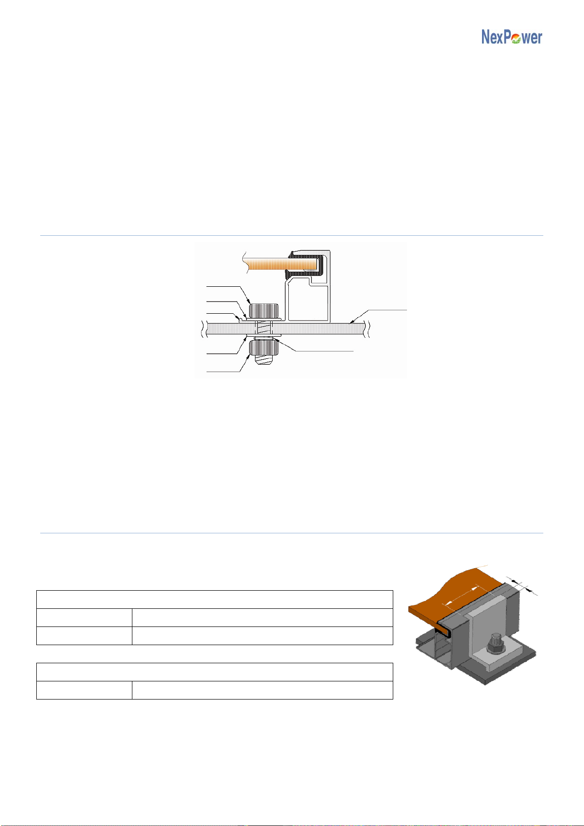
2.2.1 Bolting System
Fig. 3: Bolting system
The PV module has four holes on the long edge of its frame for mounting purpose. Please
refer to APPENDIX 1 – Appearance.
PV modules may be fastened to a support by using bolt holes that are at the bottom of the
frame with stainless bolts, washers, spring washers, and nuts.
Do NOT damage the rear surface of PV modules while fastening PV modules by bolts.
2.2.2 Clamping System
The mounting clamp and fixing plate must meet the dimensions requirements (Fig. 4).
For NT-xxx AF / NT-xxx UF
Clamp and fixing plate dimensions requirements
Length A 0.55 inch(14 mm) A≧≧0.28 inch(7 mm)
Length B B ≧1.57 inch(40 mm)
Clamp and fixing plate torque requirements
Toque 3.69~8.85 lbf-ft (5~12 N-m)
Bolt
Frame
Wash
Wash
Nu
t
Structure member
Spring Washer
A
B
Fig. 4: Clamp dimension definition

Frame Type PV Module
Copyright © NexPower Technology Corp. ~8~
For NT-xxx AX / NT-xxx UX
Clamp and fixing plate dimensions requirements
Length A 0.66 inch(17 mm) A≧≧0.28 inch(7 mm)
Length B B ≧1.57 inch(40 mm)
Clamp and fixing plate torque requirements
Toque 5.9~7.4 lbf-ft (8~10 N-m)
Fig. 5: Clamping system
The PV module can be mounted by using clamps and fixing plates.
The common clamp used for crystalline PV modules is compatible.
For more detailed or specific recommendations, please contact your PV system dealer or
module provider.
The PV modules may be mounted by using clamps or fixing plates on long edge of PV
module, which would be perpendicular (Fig. 6) or parallel to array racks (Fig. 7).
It is essential to install the PV module according to the following guidelines.
i) The clamp position (C) is from the end of the module to the centerline of the clamp or fixing
plate.
ii) The clamp position (C) should be symmetrical at each side of PV module.
iii)PV module can be mounted as desired in accordance with the instruction approved in
APPENDIX 2 – Mounting Guideline.
PV module
Support structure
Clamp Clam
p
PV module
Fixing plate
Fixing plate
PV module
PV module
Support structure

Frame Type PV Module
Copyright © NexPower Technology Corp. ~9~
Fig. 6: Mounting structure - A
Fig. 7: Mounting structure - B
2.3 Wiring
The PV module has two sunlight resistant output cables, and each is terminated with a
Multi-Contact compatible connector. The positive terminal has a female connector, and the
negative terminal has a male connector.
Connecting PV modules in series would increase voltage, while connecting in parallel would
increase current. In order to design an adequate PV system, PV modules should be
connected in series and/or in parallel depending on specifications of inverters or other
pertinent equipments.
While connecting several strings in parallel, it is necessary to keep equivalent quantity of PV
modules to each parallel string. If connected incorrectly, PV modules will become damaged.
All system wiring must conform to local electrical codes.
[UL only] All system wiring must conform to Section 690-8 of the National Electrical Code
(NEC) in USA, Canadian Electrical Code (CEC) in Canada, or local electrical codes, for an
additional multiplying factor of 125% (80% derating) which may be applicable.
[UL only] Additional devices such as ground fault, fuses, and disconnects for over-current
protection may be required, in accordance with Article 690-5 of the National Electrical Code
(NEC).
[UL only] Installation shall be in accordance with CSA C22.1, safety Standard for Electrical
Installations, Canadian Electrical Code Part 1.
PV module
Bolt & Nut
Structure member
Clamp
A
luminum frame
Frame Type PV Module
Copyright © NexPower Technology Corp. ~10~
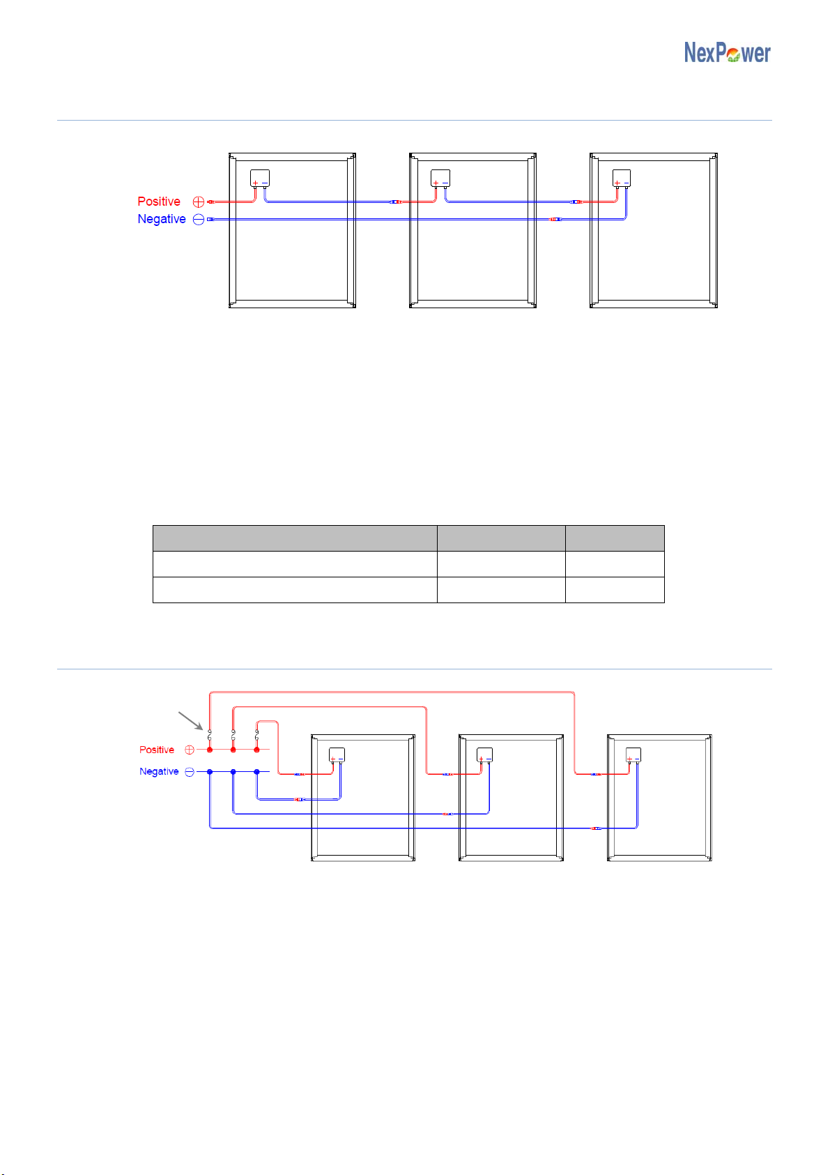
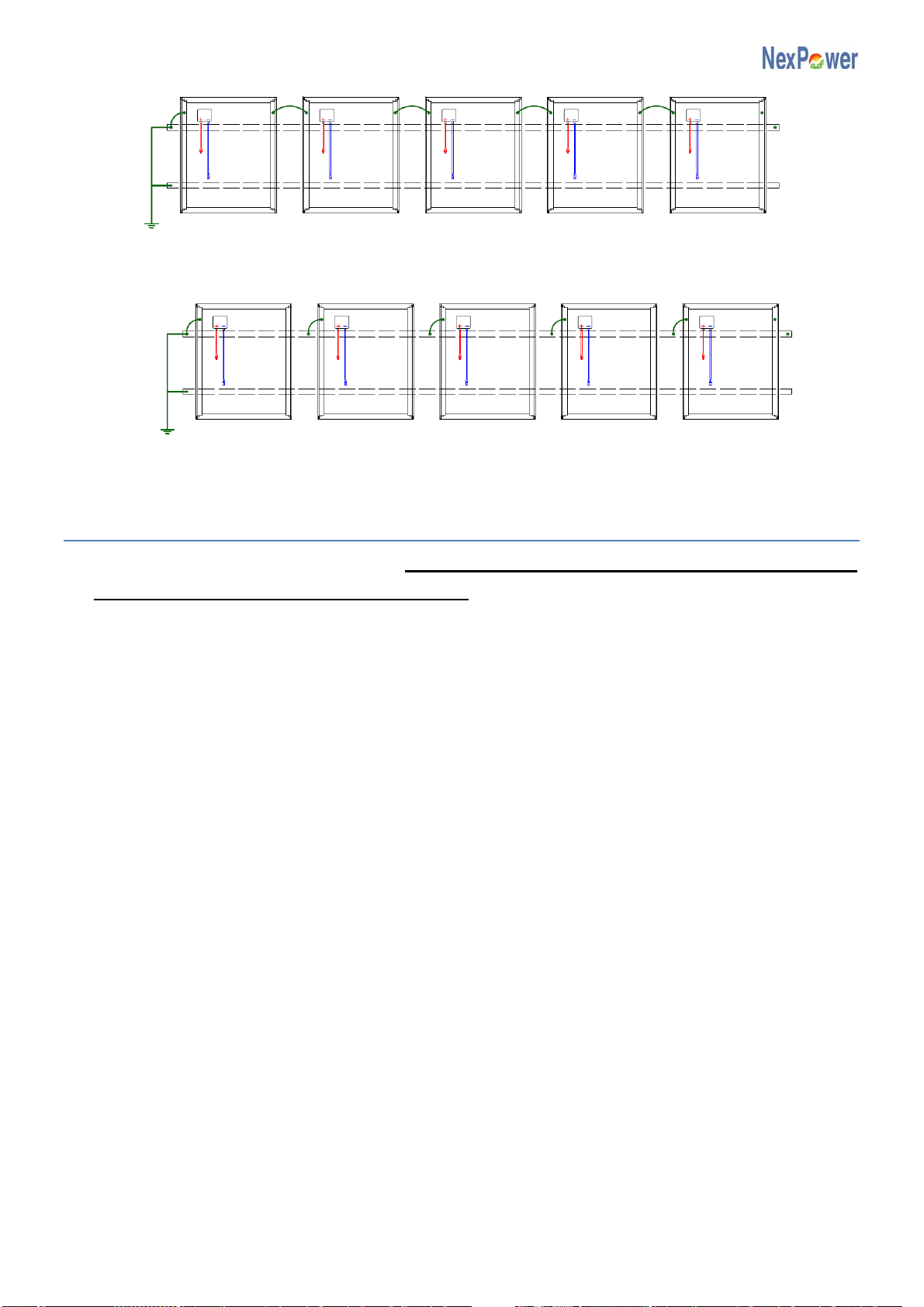
2.3.1 Series Wiring
Fig. 9: Series wiring
PV modules can be wired in series to increase voltage. Connect cables from the positive(+)/
negative(-) terminal of one module to the negative(-)/ positive(+) terminal of the next module.
When several PV modules are connected in series, the voltage and current are as below:
Vtotal = V1+ V2+ ….. + Vn
Itotal = I1= I2= ….. = In
n : number of PV modules
When determining system voltage ratings:
Requirements / Standards IEC UL
Voc multiplied factor 1.25 1.25
Maximum system voltage 1000V 600V
2.3.2 Parallel Wiring
Fig. 10: Parallel wiring
PV modules can be wired in parallel to increase current. Connect cables from the positive(+)/
negative(-) terminal of one module to the positive(+)/ negative(-) terminal of the next module.
When several PV modules are connected in parallel, the voltage and current are as below:
Vtotal = V1= V2= ….. = Vn
Itotal = I1+ I2+ ….. + In
n : number of PV modules
Please be noted that the short-circuit current of system is calculated by multiplying the Isc
listed on the module label by the number of source circuits operating in parallel. Use this
Fuse
Frame Type PV Module
Copyright © NexPower Technology Corp. ~11~
value and multiply by 1.56 to determine the conductor capacities and fuse sizes connected to
the module output.
Ensure the system design prevents a reverse current of no more than specification will
flowing through the PV module.
Parallel configuration is not limited in case of taking proper measure (e.g. fuse for protection
of module and cable from over current, and/or blocking diode for prevention of unbalanced
strings voltage) to block the reverse current flow.
2.4 Cable Selection
[IEC only] The cables should use 2.5mm2or upper grade cupper wires.
[UL only] The cables should use 14 AWG or upper grade cupper wires.
It is very important to use the proper cable with a minimum wire gauge approved for usage at
the maximum short circuit current. Smaller gauge cables and connectors can become
overheated under high currents.
The cables selected should have a temperature rating higher than 90˚C.
Series and parallel wiring should use compatible connectors as of the PV modules.
[UL only] The final array output wiring can be made to a permanent wiring system in
accordance with Article 690-13 of National Electrical Code (NEC).
2.5 Bypass Diodes
Buildings, trees, or obstructions around PV modules can cast shadows on PV modules.
Current forced through shaded part of PV modules causes additional heating and severe loss
of power.
In order to avoid this condition which may impair PV module, NexPower PV Module is
equipped with factory-installed bypass diodes.
Specification Rated value
Repetitive Peak Reverse Voltage 1000 V
Maximum Average Forward Current 5 A
2.6 Grounding
Grounding method must comply with laws or electrical regulations. Please confirm electrical
codes in the region where the PV system is installed. If the grounding should be completed in
local codes, please conform to the following steps.
Each PV module must be grounded using the grounding holes found on the frame. The PV
module has four Φ0.14 inch (Φ3.5mm) holes in the frame for grounding purpose. Select at
least one grounding hole according to PV module mounting mode.
Must apply equipment grounding at the same electrical potential level to all PV modules.
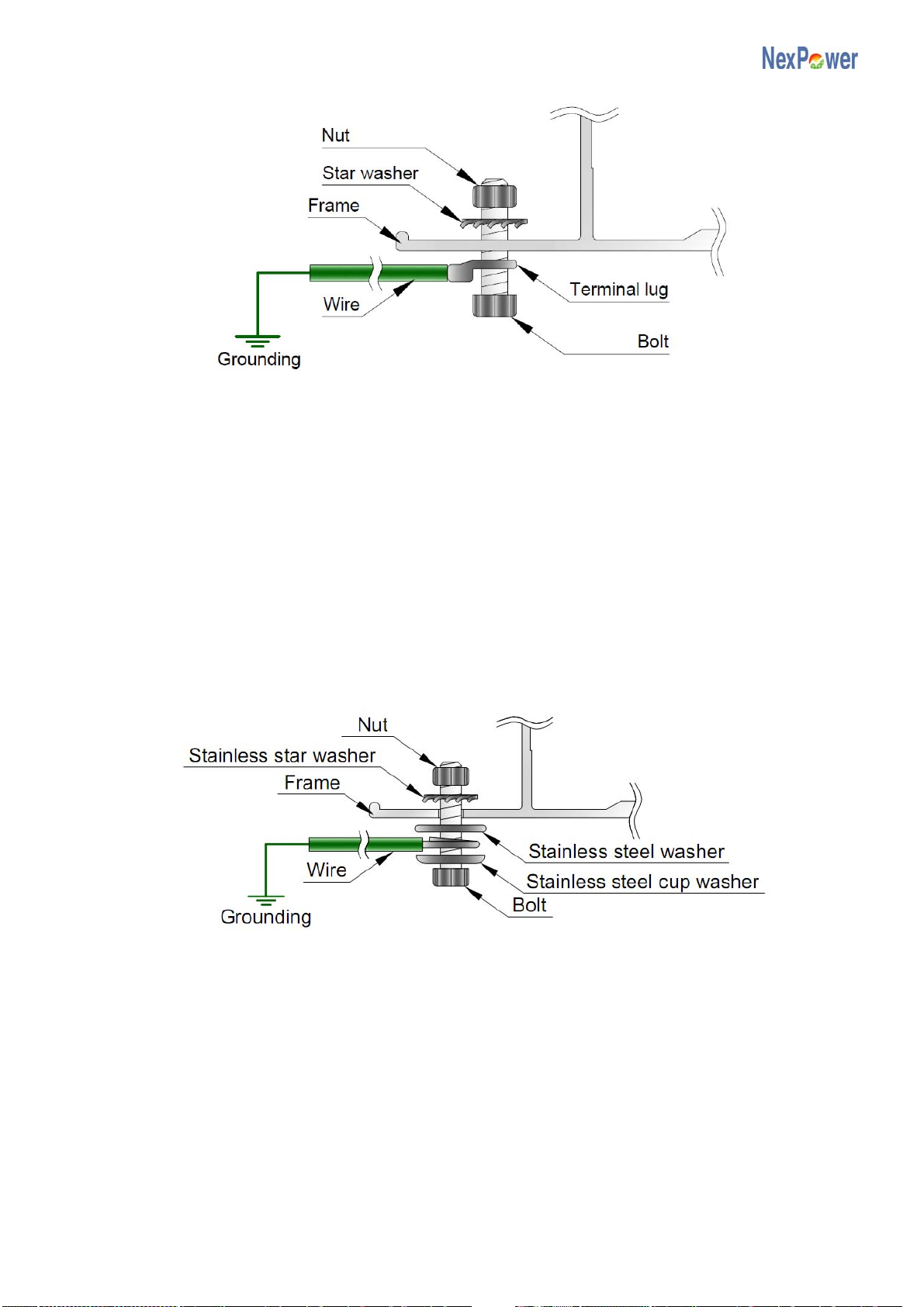
[IEC only] Grounding cables must be bolted or screwed with star washers (Fig.11).
Frame Type PV Module
Copyright © NexPower Technology Corp. ~12~
Fig. 11: Grounding connection of the PV module [IEC only]
[UL only] Grounding cables must be bolted with washers (Fig.12).
[UL only] Attach the equipment grounding conductor to the module frame by a No.6 (M3)
bolt, stainless steel cup washer, stainless steel washer, star washer (Fig.12).
[UL only] The stainless steel washer is to be placed between the grounding lead and the
aluminum frame.
[UL only] The grounding conductor size should be 14 AWG or above and must be sized
according to Table 255-122 of the National Electrical Code and with a temperature rating
higher than 90˚C.
[UL only] The torque to the bolt should be 1.0 lbf-ft (1.4 N-m).
Fig. 12: Grounding connection of the PV module [UL only]
When connecting in series, PV modules either connect to the structure members by attaching
wires to the ground holes on the frames or directly bind with the structure member at
adequate positions to deploy the grounding method at the designated equipment grounding
spot.
Support structure member must apply grounding.
Frame Type PV Module
Copyright © NexPower Technology Corp. ~13~
Fig. 13: Grounding method – A
Fig. 14: Grounding method – B
2.7 Inverter Requirement
For NexPower module requirement, it is essential to select transformer type inverters
with DC negative pole grounding function.
For more details or specific recommendations, please contact your PV system dealer or
module provider.
Structure
member
Grounding
Grounding
Structure
member

Frame Type PV Module
Copyright © NexPower Technology Corp. ~14~
3.Maintenance
3.1 Cleaning Instructions
When dirt accumulates on the surface of PV module and becomes excessively built-up,
power output may decline. When this situation occurs, it is a good manner to use only lots of
water to flush the dirt away.
Moreover, cleaning the module surface is proper but only with a soft cloth and water.
Before washing, please wear electrical insulation gloves to avoid electrical accidents.
Protect yourself against any possibility from accidents during maintenance.
If cleaning the back of the module is required, take utmost care to avoid penetrating the back
side materials.
During the cleaning process, do NOT cause any partial shading parallel to the longitudinal
direction of the module.
It is recommended to shut down the system before the cleaning process or to clean the
modules under low irradiance condition (e.g. at dawn or nightfall).
3.2 System Inspection
The PV modules are designed to last for extended period of time thus require very little
maintenance.
Check annually and carefully to ensure for fixed mounting hardware and tightened wiring.
Any loose connections or parts may cause damages in modules or arrays.
If any problem is found, please contact your local PV system dealer for professional service.

Frame Type PV Module
Copyright © NexPower Technology Corp. ~15~
APPENDIX 1 - Appearance
Front View
Rear View
A
Type Mounting hole Bolt size
NT-xxx AF/UF Φ0.26 inch
(Φ6.5 mm) M6
(Stainless)
NT-xxx AX/UX Φ0.39 inch
(Φ10 mm) M8
(Stainless)
B
Type Grounding hole Bolt size
NT-xxx AF/UF
NT-xxx AX/UX
Φ0.14 inch
(Φ3.5 mm) M3
Frame
PV cell
A
A
B
B
A
B
B
A
(Location subject to different models)
Junction Box
Frame Type PV Module
Copyright © NexPower Technology Corp. ~16~
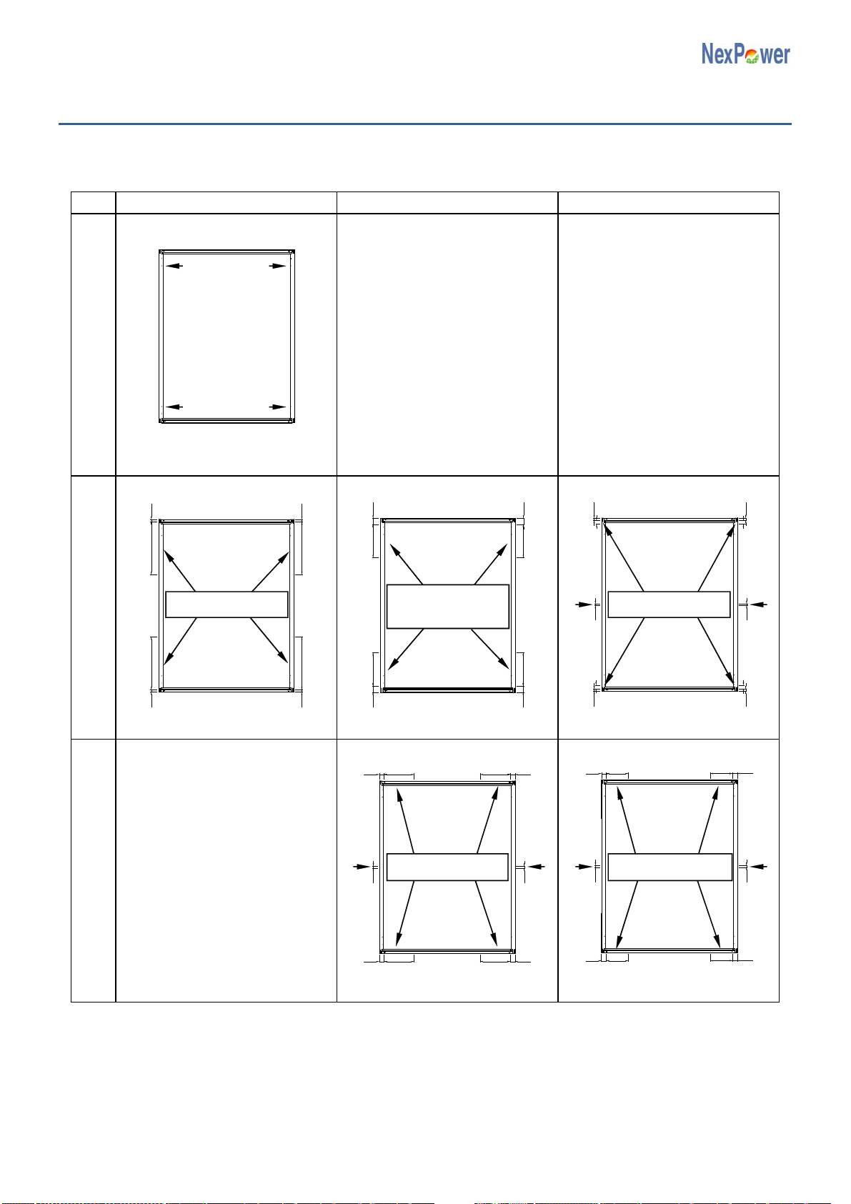
APPENDIX 2 - Mounting Guideline
2.1 For NT-xxx AF/ NT-xxx UF
Snow/Wind load 1200 Pa Snow/Wind load 2400 Pa Snow/Wind load 3000 Pa
Use four mounting holes
Use four clamps Use four clamps* Use six clamps
Use six clamps Use six clamps
* The mounting configuration is certified by the third party organization. Al403-MI-B
Clamping system
Attach to the short frame Bolting system
Attach to the mounting holes
Clamping system
Attach to the long frame
C=20to 450mm C=20to 50mm
C=40to 285mm C=40to 220mm
C=50to 110mm
240to 320mm
20
2020
20
50
50
50
50
15
15
4040
40
40
15
15
40
40
40
40
20
20
20
20 15
15
Frame Type PV Module
Copyright © NexPower Technology Corp. ~17~
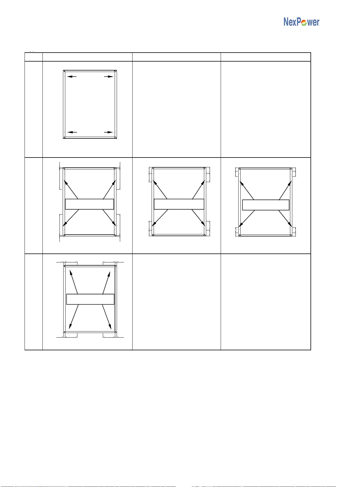
2.2 For NT-xxx AX/ NT-xxx UX
pp
Snow/Wind load 2400 Pa Wind load 3800 Pa Snow load 5400 Pa
Use four mounting holes
Use four clamps* Use four clamps Use four clamps
Use four clamps
* The mounting configuration is certified by the third party organization. Al402-MI-C
Clamping system
Attach to the short frame Bolting system
Attach to the mounting holes
Clamping system
Attach to the long frame
20
20 20
20
C=20 to 450mm
120120
120120
C=120 to 180mm
70
70
7070
C=70 to 110mm
40 40
40 40
C=40 to 285mm
This manual suits for next models
3
Table of contents


