nexstyle 03012S-HHSS User manual

Please read and save this guide through before using your
chimney hood. Store the guide away in a safe place so that
you will know where it is, when you want to refer to it.
range hood
Model#: 03012S-HHSS / 03012K-HHSS / 03012K3-HHSS
Installation
Guide and
User Manual

2
Table of Contents
A. Important Safety Instructions ................................................... 03
- Installation ............................................................................. 03
- Operations ............................................................................ 04
- Cleaning ................................................................................ 05
B. Before You Start .................................................................... 06
C. Electrical Requirements ........................................................... 10
D. List of Materials ....................................................................... 12
E. Planning for the Installation .................................................... 14
- Dimensions ........................................................................... 14
- Important .............................................................................. 14
- Venting Method ..................................................................... 16
F. Installation Instructions ............................................................ 19
G. Maintenance ............................................................................ 22
H. Trouble Shooting ..................................................................... 24
I. Range hood operations ........................................................... 26
J. Wiring Diagram ..................................................................... 26
K. Specification ............................................................................ 27
• Readandsavetheseinstructionssavethisguideforlocalelectrical
inspector’s use .
• Approvedforresidentialappliances
• Forresidentialuseonly
Installation must comply with all local codes.
• Requirement:120VAC,60Hz.15or20ABranchCircuit
• Mustreadtheentireinstructionsbeforeanyproceeding.
• Turnoffpowercircuitatservicepanelandlockoutpanel,before
wiring this appliance.
Installer: Must leave these instructions with this unit for the owner.
Homeowner: Please retain these instructions for future reference and
for local electrical inspectors’ use.

3
A. IMPORTANT SAFETY
INSTRUCTIONS
Read all Instructions before Installing and operating this appliance.
INSTALLATION
Do not install if the appliance is damaged.
1. The installation in this manual is intended for qualified installers, service
technicians or persons with similar qualified background. NEVER
attempt to install this appliance yourself.
2. Injury could result from installing the unit due to lack of appropriate
electrical and technical background.
3. All electrical wiring must be properly installed, insulated and grounded.
Old duct work should be cleaned or replaced if necessary to avoid
the possibility of a grease fire. Check all joints on duct work to insure
proper connection and all joints should be properly taped.
4.PersonalinjuryHazard-Becauseoftheweightandsizeoftherange
hood, two or more people are needed to move and safely install the
range hood. Failure to properly lift range hood could result in damage
to the product or person injury.
5. SEVERE INJURY - Range hood may have very shape edges. Please
wear protective gloves if it is necessary to remove any parts for
installing, cleaning or servicing.
IMPORTANT
Carefully check the unit prior to installation to ensure there is no damage.
Do not dispose of any packaging until you are satisfied with your new
range hood.
NOTE
Ifyouhaveanyproblemswiththeunit,pleasecalltollfree:
1-800-459-4409. Do not return the unit to the place of purchase before
calling the toll free number.

4
OPERATIONS
1. Read all instructions in this manual before operating the appliance.
2. Always leave safety grills and filters in place. Without these components,
operating blowers could catch on to hair, fingers and loose clothing
3. NEVER dispose cigarette ashes, ignitable substances, or any foreign
objects into blowers.
4. NEVER leave cooking unattended. When frying, oil in the pan can
easily overheat and catch fire. The risk of self combustion is higher
when the oil has been used several times.
5. NEVER cook on “open” flames under the range hood. Check deep-
fryersduringuse:superheatedoilmaybeammable.

5
CLEANING
Do not operate blowers when filters are removed.
1. The saturation of greasy residue in the blower and filters may cause
increased inflammability. Keep this appliance clean and free of grease
and residue build-up at all times to prevent possible fires.
2. Filters must be cleaned periodically and free from accumulation of
cooking residue (see cleaning instructions inside). Old and worn filters
must be replaced immediately.
3. NEVER disassemble parts to clean without proper instructions.
Disassembly is recommended to be performed by qualified personnel
only.
The manufacture and distributors decline all responsibility in the event of failure to
observe the instructions given here for installation, maintenance and suitable use
of the product. The manufacture and distributors further declines all responsibility
for injury due to negligence and the warranty of the unit automatically expires due
to improper maintenance.
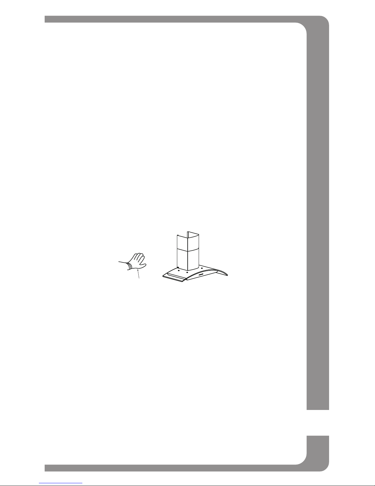
SAFETY NOTE:
Please wear “Safety Workman Gloves” for installation, cleaning, light bulb
changing and dismantling to reduce the risk of any bodily injuries.
Safety Workman Gloves

6
B. BEFORE YOU START...
It is very important for your safety and safety of others, that you follow the
many important safety messages in this manual and on your appliance.
Always read and obey all safety messages. All safety messages will tell
youwhatthepotentialhazardis,tellyouhowtoreducethechanceof
injury, and tell you what can happen if the instructions are not followed.
This safety alert symbol alerts you to potential hazards that can kill
or hurt you and others. All safety messages will follow the safety
alert symbol and the word “WARNING”.
READ AND SAVE THESE INSTRUCTIONS
WARNING : TO REDUCE THE RISK OF FIRE, ELECTRIC SHOCK, OR
INJURY TO PERSON OBSERVE THE FOLLOWING CAREFULLY:
1) Use this unit only in the manner intended by the manufacturer. If
you have any questions, contact the distributor, importer or the
manufacturer.
2) Before servicing or cleaning unit, switch power off at service panel
and lock service disconnecting means to prevent power from being
switched on accidentally. When the service disconnecting means
cannot be locked, securely fasten a prominent warning device, such
as a tag, to the service panel.
3) Installation work and electrical wiring must be done by qualified
person(s) in accordance with all applicable codes and standards,
including fire-related construction.

7
4) Sufficient air is needed for proper combustion and exhausting of gases
through the flue (Duct cover) of fuel burning equipment to prevent
back drafting. Follow the heating equipment manufacturer’s guideline
and safety standards such as those published by the National Fire
Protection Association (NFPA), and the American Society for Heating,
Refrigeration and Air Conditioning Engineers (ASHRAE), and the local
code authorities.
5) When cutting or drilling into the wall or ceiling, do not damage electrical
wiring and hidden utilities.
6) Dusted fans must always be vented to the outdoors.
WARNING: To reduce the risk of fire, use only metal duct work.
CAUTION: For general ventilating use only. do not use the exhaust
hazardousorexplosivematerialsorvapors
WARNING : To reduce the risk of injury to persons in the event of
a range top grease fire, observe the following: (based in “kitchen
fire safety tips” published by NFPA)
1) SMOTHER FLAMES with a close-fitting lid, cookie sheet, or metal tray,
then turn off the burner. BE CAREFUL TO PREVENT BURNS. If the
flames do not go out immediately, EVACUATE AND CALL THE FIRE
DEPARTMENT.
2) NEVER PICK UP A FLAMING PAN - you may be burned.
3) DO NOT USE WATER, including wet dishcloths or towels - a violent
steam explosion will result.
4) UseanextinguisherONLYif:
a) You know you have a class ABC extinguisher, and you already know
how to operate it.
b) The fire is small and contained in the area where it started.
c) The fire department is being called.
d) You can fight the fire with your back to an exit.

8
CAUTION: To reduce risk of fire and to properly exhaust air, be sure to
duct air outside - do not vent exhaust air into spaces within walls, ceil-
ings, attics, crawl spaces, or garages.
WARNING: To reduce the risk of fire or electric shock, do not use this
hood with any external solid state speed control device.
WARNING: To reduce the risk of a range top grease fire
1) Never leave surface units unattended at high settings. Boil over cause
smoking spill-overs that may ignite. Heat oils slowly on low or medium
settings.
2) Always turn hood on when cooking at high heat or when cooking
ambefoods.(i.e.CrepesSuzette,CherriesJubilee,PeppercornBeef
Flambe).
3) Clean ventilating fans frequently. Grease should not be allowed to
accumulate on fan or filter.
4) Useproperpansize.Alwaysusecookwareappropriateforthesizeof
the surface element.
To get the best performance, the vertical clearance between the cook-
top and the range hood should range from 28” to 32” (71.1 cm - 81.3
cm)

9
GROUNDING INSTRUCTIONS
This appliance must be grounded. In the event of an electrical short
circuit, grounding reduces the risk of electric shock by providing an
escape wire for the electric current. This appliance is equipped with a
cord having a grounding wire with a grounding plug. The plug must be
plugged into an outlet that is properly installed and grounded.
WARNING: Improper grounding can result in a risk of electric shock.
Consult a qualified electrician if the grounding instructions are not
completely understood, or if doubt exists as to whether the appliance is
properly grounded.
Do not use an extension cord. If the power supply cord is too short,
have a qualified electrician install an outlet near the appliance.
CAUTION: The range hood has a thermally protected system for the
motor, which will shut down automatically if the motor is overheated.
If the overheat protection trips, disconnect the power and wait for 10
minutes until the motor cools down.

10
C. ELECTRICAL REQUIREMENTS
OBSERVE ALL GOVERNING CODES AND ORDINANCES
IMPORTANT: It is customer’s responsibility to contact a qualified electri-
cal installer and assure that the electrical installation is adequate and in
conformance with National Electrical Code, or CSA standards and all
local codes and ordinances.
1. Save installation instructions for electrical inspector’s use.
2. If codes permit and a separate ground wire is used, it is recommended
that a qualified electrician determines that if the ground path is
adequate.
3. Please remove the house fuse or open circuit before any installation
for personal safety. DO NOT use extension code or adapter plug with
this appliance.
4. RISK OF ELECTRICAL SHOCK - This range hood must be properly
grounded.
5. The range hood must be connected with copper wire only.
6. The range hood should be connected directly to the fused disconnect
(or circuit breaker) box through flexible, armored or nonmetallic
sheathed copper cable. Allow some slack in the cable so the
appliance can be moved if servicing is ever necessary.
WARNING
* Electrical ground is required on this range hood.
* Check with a qualified electrician if you are not sure whether the range
hood is properly grounded.
* Failure to follow electrical requirements may result in a fire.
* A fuse in the neutral or grounding circuit could result in electrical shock.
* If cold water pipe is interrupted by plastic nonmetallic gaskets or other
materials, DO NOT use for grounding.
** DO NOT have a fuse in the neutral or grounding circuit.
* * DO NOT ground to a gas pipe.

11
7. A UL or C.S.A. listed conduit connector must be provided at
each end of the power supply cable (at the range hood and at the
junction box).
8. When making the electrical connection, cut a 1-1/4” hole in the
wall. A hole cut through wood must be sanded until smooth. A hole
through metal must have a grommet.
9. When cutting or drilling into wall or ceiling, do not damage electrical
wiring and other hidden utilities.
10.WiresizesmustconformtotherequirementsoftheNational
Electrical Code ANSI/NFPA 70 - latest edition*, or CSA Standards
C22.1-94, Canadian Electrical Code Part 1 and C22.2 No. 0-M91
- latest edition** and all local codes and ordinances.
11.Connect three wires according to color (Black to Blue, White to
Brown, and Green to Yellow/Green) to house wires and cap with
wire connectors.
White
Black Green
BLACK TO BLUE ( Neutral )
WHITE TO BROWN ( Hot )
GREEN TO YELLOW/GREEN ( Ground )
* National Fire Protection Association Batterymarch Park Quincy,
Massachusetts 02269
** CSA International 8501 East Pleasant Valley Road Cleveland,
Ohio 44131-5575
WARNING
HAZARD OF ELECTRICAL SHOCK!
Do not perform service on an electrically
live system. Disconnect the main electrical
supply before servicing this device.
Touching electrical connectors or other
exposed electrical circuitry inside this range
hood when they are energized could result
in death, serious bodily injury, or property
damage.

12
D. LIST OF MATERIALS
TOOLS FOR INSTALLATION:
PARTS SUPPLIED:
DESCRIPTION QUANTITY
Main body (Body of Hood) includes aluminum filters ...................... 1 Set
Toggle Bolts................................................................................. 4 Sets
Duct Set ....................................................................................... 1 Set
Body Hook ................................................................................... 2 Pcs
Upper duct cover and Lower duct cover....................................... 1 Set
5mm x 16mm Screw with Washer ................................................. 1 Pc
4mm x 16mm Screw .................................................................... 6 Pcs
4mm x 8mm Tapping Screw......................................................... 4 Pcs
Duct Cover’s Fix Panel................................................................... 1 Pc
Marker or
pencil
Measuring tape
level
Powered
screwdriver
or drill
Utility Knife
Philips
screwdrivers
Flat-blade
screwdrivers
Tape
Adjustable
wrench

13
Notice:
1. Remove the range hood from the carton packaging and place on a
flat surface for assembly.
2. Check carefully to make sure that no mounting hardware or parts are
missing.
3. DO NOT REMOVE THE PLASTIC COVERING ON THE DUCT
COVERS AT THIS TIME. As it protects the duct covers from
scratches during installation
Upper Duct Cover
& Lower Duct Cover
1set
Range Hood
(vary with model)
1set
Duct cover's
fix panel 1pc
Screws box
Body Hook
2 pcs
4mm x 16mm
Screws 6 pcs
4mm x 8mm
Tapping Screws
4 pcs
5mm x 16mm
Screws & Washer
4 pcs
Installation
Guide
Toggle Bolts
4 sets

14
E. PLANNING FOR THE INSTALLATION
1. DIMENSIONS:
B. IMPORTANT: Must measure following steps before installation.
The Duct covers are adjustable and designed to meet varying ceiling
height. The chimneys can be adjusted for ceiling between 8 ft. (243.84
cm) and 9 ft. (274.32 cm) depending on the distance between the bot-
tom of the hood and the cook top).
WARNING
* Proper installation is your responsibility - Must have a qualified technical to install this range hood.
* Read the entire installation guide and users manual thoroughly, and understand instructions and warning.
* PERSONAL INJURY HAZARD - Because of the weight and size of the range hood, two or more people
are needed to move and safely install the range hood. Failure to properly lift range hood could result in
damage to the product or person injury.
* All opening in ceiling and wall where range hood will be installed must be sealed.
* Range hood location should be away from strong draft areas (windows, doors and strong heating vents).
* SEVERE INJURY - Rotating fan ca cause severe injury. Stay clear of fan when motor is running.
* SEVERE INJURY - Range hood may have very shape edges. Please wear protective gloves if it is
necessary to remove any parts for installing, cleaning or servicing.

15
For shorter ceilings, have a duct cover made at a sheet metal shop. For
higher ceilings, buy an extra upper chimney which would replace the
original one that came with the hood.
1) Distance from the floor to the ceiling.
2) Distance between the floor to the counter top/stove.
3) Distance between the counter/stove and range hood
(recommended 28” (71.1 cm) to 32” (81.3 cm).
4) Height of range hood and chimney.
5) Height of the range hood installation
* Higher ceiling requires
chimney extension.
Range Hood
Lower Duct Cover
Upper Duct Cover
Air Deflector
(optional)
36" min.
(91.4 cm)
Ceiling
Height
Chimney extensions
available for higher
ceiling
Min: 28" (71.1 cm)
Max: 32" (81.3 cm)

16
3. VENTING METHODS
This range hood can be installed as either ducted or ductless.
a. OUTDOOR VENTING METHODS (for outdoor venting through the
roof or wall only)
The hood is equipped with a transition “duct set” for discharge of fumes
to the out door. Vent work can terminate either through the roof or wall.
To vent through a wall, a 90 degree elbow is used.
IMPORTANT:
- Vent system must terminate to the outside(through roof or side wall),
unless using a ductless recirculating kit (charcoal filter).
- Do not terminate the vent system in an attic or any other enclosed
area.
- Recommended to use metal / flexible aluminum vent only.
- Never use plastic vent.
- Always Keep the duct clean to ensure the proper airflow.
- NEVER exhaust air or terminate duct work into spares between walls,
crawl spaces, ceiling, attics or garages. All exhaust must be ducted to
the outside.
- Use caulking to seal exterior wall or roof opening around the cap.
- Do not use 4” (10.2cm) laundry-type wall caps.
Example 1. Vertical roof venting. Example 2. Horizontal wall venting
Ducting through the roof
Ducting through the wall
Roof
Pipe
Duct cover
Roof Cap
Wall Cap
Duct cover
Wall
Pipe

17
- Always keep the duct clean to ensure proper airflow.
- It is recommended that the range hood be vented vertically through
the roof through 6” (15.2 cm) round metal/aluminium vent work. The
sizeoftheventshouldbeuniform.
- Use no more than three 90oelbows and do Not install two elbows
together.
- Make sure there is a minimum of 24”(61cm) of straight vent between
the elbows if more than one elbow is used. The length of vent system
and number of elbows should be kept to a minimum to provide efficient
performance.
- The vent system must have a damper. If roof or wall cap has a damper,
Do Not use damper supplied with the range hood.
- Use duct tape to seal all joints in the vent system.
- Fasten all connections with sheet metal screws and tape all joints with
certified Silver Tape or Duct Tape.
Calculate the duct run length:
If ducted with the required minimum of 6” round duct work, the duct run
should not exceed 35 equivalent feet. Calculate the length of the duct
work by adding the equivalent feet as below for each piece of duct in the
system.
If you must elbow right away, do it as far away from the hood’s exhaust
opening as possible.
45oElbow - 3.0 feet
90oElbow - 5.0 feet
90oFlat Elbow - 12.0 feet
Wall Cap - 0.0 feet
9 Feet Straight Duct 9.0 feet
2-90oElbow 10.0 feet
Wall Cap 0.0 feet
Total System 19.0 feet

18
(b). Duct less Recirculating Kit (Charcoal Filter)
- Ductless conversion is intended for applications where an exhaust
duct work is not possible to be installed. When converted, the hood
functions as a purifying hood rather than an exhaust hood. Fumes and
exhaust from cooking is drawn and filtered by a set of charcoal filters.
The air is then purified and re-circulated back within the home.
- Ductless conversion is a “ purifying” unit, a set of charcoal filter and an
air deflector are required in addition to it standard aluminum filter set.
- The aluminum filter are intend to capture residue from cooking, the
optional charcoal filter helps to purify fumes exhausted from cooking,
and the optional air deflector redirects filter clean air back to the
house.
WARNING: Before making any cuts or holes for installation, determine
which venting method will be used and carefully calculate all
measurements.
Install the aluminium tube onto
the air deflector.
Air - flow
Air deflector
Flexible Aluminum tube Safety filter Charcoal Filter

19
F. INSTALLATION INSTRUCTIONS
- Before making cutouts, make sure there is proper clearance within
the ceiling or wall for exhaust vent.
- Check your ceiling height and the hood height maximum before you
select and install your hood. The hood installation height above cook
top is user preference. The lower the hood above the cook top, the
more efficient the capturing of cooking odors, grease and smoke. The
hood should be installed at 28” (71.1cm) minimum to 32” (81.3 cm)
above the counter top.
- Fitting material is provided to secure the hood to most types of walls.
However, a qualified technician must verify suitability of the materials
in accordance with the type of wall. Must consult a qualified installer
and check if the screws and drywall anchor perfectly fit with your
cabin/wall.
- Due to the size and weight of this range hood, the support must
be firmly attached to the ceiling. For plaster or sheet rock ceilings,
the support must be attached to the joists. If this is not possible, a
support structure must be built behind the plaster or sheet rock. The
manufacturer assumes no responsibility for injury or damage caused
by improper installations.
- Put a thick, protective covering over counter top, cook top or range to
protectfromdamageordirt.Removeanyhazardousobjectsaround
the area when installing.
1. Locate an optimal location to place the range hood. Mark the leveling
points for two Body Hooks (figure. 1) on the wall and drill two holes
Insert two toggle bolts and reserve approximately 1/4” (6.3 cm) for the
body hooks. Be sure to use appropriate anchors for your wall.
Wall
(Fig. 1)
Hanging on
1/4"
away from
the wall
Body of Hood
Ceiling
toggle bolts
Appropriate
length
」X5x16 screw
and washer
Body Hook
(Fig. 2)
6pcs of 」X4 x 16 screw
(Fig. 3)
Duct Set

20
2. Use four sets of 5mm x 16mm screws with washer to install the body
hooks onto the hood (See figure 2).
3. Install the duct set using six 4mm x 16mm screw (See figure 3).
DUCTED INSTALLATION METHOD (vented to the outside)
4. Find an optimal location for the duct cover’s fix panel. The fix panel
must be placed directly above and align with the two body hooks. Drill
two more holes insert two toggle bolts. Secure the fix panel with 2
toggle bolts and screw tightly. Be sure to use appropriate anchors for
your wall. (figure 4)
(Fig. 6)
Lower
duct cover
Upper
duct cover
Duct cover's fix panel
」X4 x 8 screw
」X4 x 8 screw
(Fig. 4)
Hanging on
1/4"
away from
the wall
Body of Hood
11-13/32"
31/32"
Ceiling
Toggle Bolts
Wall
Duct Cover's
fix panel
1/8"
(Fig. 5)
Install the Duct set
and Aluminium tube
on the body of hood.
WARNING
Because of the weight and size of the range hood,
two or more people are needed to move and safely
install the range hood. Failure to properly lift range
hood could result in damage to the product or
personal injury. Hood may have very shape edges.
Please wear protective gloves if it is necessary to
remove any parts for installing.
PERSONAL INJURY HAZARD
This manual suits for next models
2
Table of contents
Other nexstyle Ventilation Hood manuals