nexstyle 654OSA009STS Assembly instructions

Please read and save this guide before using your range hood.
Store the guide in a safe place so you will know where it is
when you want to refer to it.
stainless steel
range hood
Model#: 654OSA009STS
Installation
Guide and
User Manual

2
IMPORTANT
Carefully check the unit prior to installation to ensure there is no damage.
Do not dispose of any packaging until you are satisfied with your new
range hood.
If you have any problems with this unit or there are
missing or damaged parts, please call toll free:
1-800-459-4409
DO NOT RETURN THE UNIT TO THE PLACE OF PURCHASE
before calling the toll free number above.
• Readandsavetheseinstructions.Savethisguideforlocalelectrical
inspector’s use.
• Approvedforresidentialappliances.
• Forresidentialuseonly.
Installation must comply with all local codes.
• Requirement:120VAC,60Hz.15or20ABranchCircuit.
• Readallinstructionsbeforeproceeding.
• Turnoffpowercircuitbreakerbeforewiringthisappliance.
Installer: Must leave instructions for this unit with owner.
Homeowner: Please retain these instructions for future reference and
for local electrical inspector’s use.

3
IMPORTANT SAFETY INSTRUCTIONS
Readallinstructions before installing and operating this appliance.
INSTAllATION
Do not install if the appliance is damaged.
1.The instructions in this manual are intended for qualied installers,
service technicians or other qualied persons. NEVER attempt to
install this appliance yourself.
2.Installingtheunitwithoutanelectricalandtechnicalbackgroundcould
result in injury.
3.Allelectricalwiringmustbeproperlyinstalled,insulatedandgrounded.
Old duct work should be cleaned or replaced if necessary to avoid
the possibility of a grease fire. Check all joints on duct work to ensure
properconnection.Alljointsshouldbeproperlytaped.
4.Personalinjuryhazard.Becauseoftheweightandsizeoftherange
hood,twoormorepeopleareneededtomoveandsafelyinstallthe
rangehood.Failuretoproperlyliftrangehoodcouldresultindamage
to the product or personal injury.
5.SEVEREINJURY-Rangehoodmayhaveverysharpedges.Please
wearprotectiveglovestoremoveanypartsforinstalling,cleaningor
servicing.
6.DO NOT INSTALL CLOSER THAN 61 CM (24 INCHES) ABOVE
COOKING SURFACE.
OPERATIONS
1.Readallinstructionsinthismanualbeforeoperatingtheappliance.
2.Alwaysleavesafetygrillsandltersinplace.Withoutthesecomponents,
operatingblowerscouldcatchontohair,ngersandlooseclothing.
3.NEVERdisposeofcigaretteashes,ignitablesubstances,oranyforeign
objects in blowers.
4.NEVERleavecookingunattended.Usecautionwhencookingwithoil.
Overheatingmaycauseoiltoreachitsashpointandignite.Usedoil
will ignite at lower temperatures than fresh oil.
5.NEVER cook over open ames under the range hood. Constantly
monitordeep-fryersduringuse,asoverheatedoilmayignite.

4
ClEANINg
Do not operate blowers when filters are removed.
1.Thesaturationofgreasyresidueintheblowerandltersmaycause
increased flammability. Keep this appliance clean and free of grease
andresiduebuild-upatalltimestopreventpossibleres.
2.Filtersmustbecleanedperiodicallyandkeptfreefromaccumulation
of cooking residue (see cleaning instructions inside). Old and worn
filters must be replaced immediately.
3.NEVERdisassemblepartstocleanwithoutproperinstructions.Parts
shouldbedisassembledbyqualiedpersonsonly.
The manufacture and distributors decline all responsibility in the event of failure to
observe the instructions given here for installation, maintenance and suitable use
of the product. The manufacturer and distributors further decline all responsibility
for injury due to negligence and the warranty of the unit automatically expires due
to improper maintenance.
SAFETY NOTE:
Remove PVC lm before installation. Always wear “Workman Safety
Gloves”forinstallation,cleaning,lightbulbreplacementanddismantling
to reduce the risk of injury.
READ AND SAVE THESE INSTRUCTIONS
Workman Safety Gloves

5
BEFORE YOU START...
Itisveryimportantforyoursafetyandthesafetyofothersthatyoufollow
the many important safety messages in this manual and on your appli-
ance.Always readandobey allsafety messages.All safetymessages
willtellyouwhatthepotentialhazardis,howtoreducethepossibilityof
injury,andwhatcanhappeniftheinstructionsarenotfollowed.
This safety alert symbol alerts you to potential hazards that can kill
or hurt you and others. All safety messages will follow the safety
alert symbol and the word “WARNING.”
WARNING: TO REDUCE THE RISK OF FIRE, ELECTRIC
SHOCK, OR INJURY TO PERSONS, OBSERVE THE FOLLOWING
CAREFULLY:
1) Use this unit only in the manner intended by the manufacturer. If
you have any questions, contact the distributor, importer or the
manufacturer.
2) Beforeservicingorcleaningtheunit,switchpoweroffatthejunction
box and lock the panel door to prevent power from being switched on
accidentally.Ifthejunctionboxdoorcannotbelocked,securelyfasten
a prominent warning sign to the panel door.
3) Installation work and electrical wiring must be done by qualied
person(s) in accordance with all applicable codes and standards,
includingre-relatedconstruction.
4) Sufficient air is needed for proper combustion and exhausting of gases
through the ue (duct cover) of fuel burning equipment to prevent
backdrafting.Followtheheatingequipmentmanufacturer’sguidelines
and safety standards such as those published by the National Fire
ProtectionAssociation(NFPA)andtheAmericanSocietyforHeating,
RefrigerationandAirConditioningEngineers(ASHRAE),andthelocal
code authorities.
5) Whencuttingordrillingintothewallorceiling,donotdamageelectrical
wiring and hidden utilities.

6
6) Ductedfansmustalwaysbeventedtotheoutdoors.
WARNING:Toreducetheriskofre,useonlymetalductwork.
CAUTION: Forgeneralventilationuseonly.Donotusetherangehood
fanstoexhausthazardousorexplosivevapours.
WARNING : To reduce the risk of injury in the event of a range
top grease fire, observe the following: (Basedon“kitchenresafety
tips”publishedbytheNFPA)
1) SMOTHERFLAMESwithaclose-ttinglid,cookiesheet,ormetaltray,
thenturnofftheburner.BECAREFULTOPREVENTBURNS.Ifthe
amesdonotgooutimmediately,EVACUATEANDCALLTHEFIRE
DEPARTMENT.
2) NEVERPICKUPAFLAMINGPAN-youmaybeburned.
3) DONOTUSEWATER,includingwetdishclothsortowels-aviolent
steam explosion will result.
4) UseanextinguisherONLYif:
a)YouknowyouhaveaclassABCextinguisher,andyoualreadyknow
how to operate it.
b)Thereissmallandcontainedintheareawhereitstarted.
c)Theredepartmentisbeingcalled.
d)Youcanghttherewithyourbacktoanexit.
CAUTION:Toreduceriskofreandtoproperlyexhaustair,besureto
ventairoutside-donotventexhaustairintospaceswithinwalls,ceil-
ings,attics,crawlspaces,orgarages.
WARNING: Toreducetheriskofreorelectricshock,donotusethis
hood with any external solid state speed control device.

7
WARNING: FOR GENERAL VENTILATION USE ONLY. DO
NOT USE THIS RANGE HOOD TO VENTILATE HAZARDOUS OR
EXPLOSIVE MATERIAL AND VAPOURS.
TO REDUCE THE RISK OF A RANGE TOP GREASE FIRE:
1) Neverleaverangeunattendedwheninuse.
2) Boiloverscausesmokingandgreasyspilloversthatmayignite.
3 Heatoilsslowlyonlowormediumsetting.
4) AlwaysturnhoodONwhencookingathighheatorwhencooking
amingfoods(i.e.CrepesSuzette,CherriesJubilee,Peppercorn
BeefFlambe).
5) Cleanventilationfansfrequently.
6) Greaseshouldnotbeallowedtoaccumulateonfanorlters.
7) Useproperpansize.
8) Alwaysusecookwareappropriateforthesizeofthesurfaceelement.
Togetthebestperformance,theverticalclearancebetweenthecook-top
andtherangehoodshouldrangefrom61cm-76.2cm(24in.to30in).
gROUNDINg INSTRUCTIONS
Thisappliancemustbegrounded.Intheeventofanelectricalshortcircuit,
grounding reduces the risk of electric shock by providing an escape wire
for the electric current.
WARNINg: Improper grounding can result in a risk of electric
shock.Consultaqualiedelectricianifthegroundinginstructionsarenot
completely understood or if doubt exists as to whether the appliance is
properly grounded.
CAUTION: The range hood has a thermally protected system for the
motor, which will shut down automatically if the motor is overheated.
If the overheat protection trips, disconnect the power and wait for 10
minutes until the motor cools down.

8
ElECTRICAl REQUIREMENTS
OBSERVE ALL GOVERNING CODES AND ORDINANCES
IMPORTANT: It is the customer’s responsibility to contact a qualied
electricalinstallerand assure thatthe electricalinstallationis adequate
andcomplieswiththeNationalElectricalCode,orCSAstandardsandall
local codes and ordinances.
1. Saveinstallationinstructionsforelectricalinspector’suse.
2. Ifcodespermitandaseparategroundwireisused,itisrecommended
thataqualiedelectriciandetermineifthegroundpathisadequate.
3. DONOTuseanextensioncordoradapterplugwiththisappliance.
4. RISKOFELECTRICALSHOCK-Thisrangehoodmustbeproperly
grounded.
5. Therangehoodmustbeconnectedwithcopperwireonly.
6. Therangehoodshouldbeconnecteddirectlytothejunction(orcircuit
breaker) box through exible, armoured or nonmetallic sheathed
coppercable.Allowsomeslackinthecablesotheappliancecanbe
moved if servicing is ever necessary.
7. AULlistedorCSAapprovedconduitconnectormustbeprovided
at each end of the power supply cable (at the range hood and at the
junction box).
8. Whenmakingtheelectricalconnection,cuta3.2cm(1-1/4in.)hole
inthewall.Aholecutthroughwoodmustbesandeduntilsmooth.
Aholethroughmetalmusthaveagrommet.
WARNING
* Electrical grounding is required for this range hood.
* Check with a qualified electrician if you are not sure whether the range
hood is properly grounded.
* Failure to follow electrical requirements may result in a fire.
* A fuse in the neutral or grounding circuit could result in electrical shock.
* If the hot/cold water pipe is interrupted by plastic nonmetallic gaskets or
other materials, DO NOT use for grounding.
* * DO NOT ground to a gas pipe.

9
9. Whencuttingordrillingintothewallorceiling,donotdamage
electrical wiring and other hidden utilities.
10.WiresizesmustconformtotherequirementsoftheNational
ElectricalCodeANSI/NFPA70-latestedition*,orCSAStandards
C22.1-94,CanadianElectricalCodePart1andC22.2No.0-M91-
latestedition**andalllocalcodesandordinances.
11.ConnectBlacktoBlack,WhitetoWhiteandGreentoGreen
wires from the range hood to the house wiring and cap with wire
connectors.
Wiring from
electrical source
Range hood wiring
White (N)
Black (L) Yellow/Green (G)
BLACK ( Live )
WHITE ( Neutral )
GREEN/YELLOW ( Ground )
* National Fire Protection Association Batterymarch Park Quincy,
Massachusetts 02269
**CSA International, 178 Rexdale Boulevard, Toronto, Ontario,
CANADA, M9W 1R3
WARNING
ELECTRICAL SHOCK HAZARD
Do not perform service on an electrically
live system. Disconnect the main electrical
supply before servicing this device.
Touching electrical connectors or other
exposed electrical circuitry inside this range
hood when they are energized could result
in death, serious bodily injury, or property
damage.

10
lIST OF MATERIAlS
TOOLS FOR INSTALLATION:
Notice:
1.Removetherangehoodfromthecartonpackagingandplaceona
flat surface for assembly.
2.Checkcarefullytoensuretherearenomissingpartsormounting
hardware.
3.Wheninstalling,cleaningorperformingmaintenance,itis
recommended wearing safety glasses and safety gloves.
4. WARNING:Toavoiddangerofsuffocation,keeptheplastic
thatcoverstheunitawayfromchildren.Donotuseincribs,beds,
carriagesorplaypens.Thebagisnotatoy.Discardbagandallother
packing materials immediately after removing the unit. Do not reuse
the bag.
marker or
pencil
needle nose
pliers hammer
measuring tape
level
powered
screwdriver
or drill
utility knife
Philips
screwdrivers
flat-blade
screwdrivers
tape
adjustable
wrench

11
SUPPLIED PARTS:
ø
4 mm x 8 mm tapping screw x 2
ø
5 mm x 30 mm tapping screw x 4
damper x 1
installation guide
range hood x 1
Qty.
Description
Range Hood (with 2 filters) 1
Damper (located inside the hood) 1
ø4 mm x 8 mm tapping screw 2
ø5 mm x 30 mm tapping screw 4
Installation Guide 1

12
PlANNINg FOR INSTAllATION
DIMENSIONS:
MEASUREMENTS:
Thisproductisdesignedforundercabinetinstallation.
Beforeinstallation,measurealldistancestoensuretheproperposition
of the range hood.
1) Distancefromtheoortotheceiling.
2) Distancebetweentheoortothecountertop/stove.
3)
Distancebetweenthecounter/stoveandrangehood61cmto76.2cm
(24into30in).Foroptimalperformance,therangehoodshouldnot
beinstalledmorethan76.2cm(30in)fromcooktop.
4) Heightofcabinet.
5) Heightoftherangehoodinstallationlocation.
6)Determineifyourexistingventingsystemistoporbackventing
before any installation begins.
DO NOT INSTAll ClOSER THAN 61 CM
(24 INCHES) ABOVE COOKINg SURFACE
WARNING
* Proper installation is your responsibility - Have a qualified technician install this range hood.
* Read the entire installation guide and user manual thoroughly, and understand instructions and warnings.
* PERSONAL INJURY HAZARD - Because of the weight and size of the range hood, two or more people
are needed to move and safely install the range hood. Failure to properly lift range hood could result in
damage to the product or personal injury.
* All openings in ceiling and wall where range hood will be installed must be sealed.
* Range hood location should be away from strong draft areas (windows, doors and strong heating vents).
* SEVERE INJURY - Rotating fan can cause severe injury. Stay clear of fan when motor is running.
* SEVERE INJURY - Range hood may have very sharp edges. Please wear protective gloves to remove
any parts for installing, cleaning or servicing.
22.8 cm
(9 in)
75.7 cm
(29.8 in)
6.5 cm
(2.5 in)
30.5 cm
(12 in)
45.8 cm
(18 in)

13
OPERATION TEST:
Beforepermanentlymountingtherangehood,temporarilywiretherange
hood and test for proper operation. If the rangehood is not operating
correctly do not continue with the installation.
PREPARE HOOD LOCATION:
Ifthebottomofthecabinetisrecessed,addwoodllerstripsoneach
side.Thewoodstripsmustbeasthickastherecess.Usingappropriately
sizedwoodscrews,attachllerstripsinthelocationsshown.
Range Hood
Appox. 91.4 cm (36 in)
Min: 61 cm (24 in)
Max: 76.2 cm (30 in)
Ceiling
Height
Cabinet Bottom
Wall
Wood Filler Strips
(Bottom View)
14
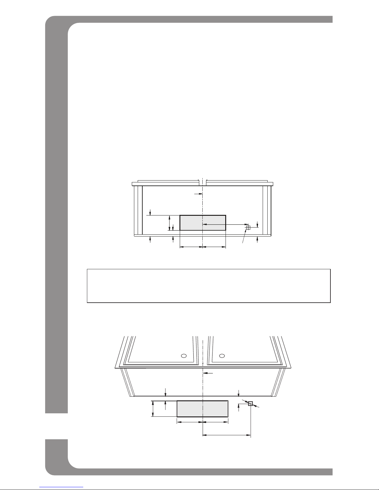
OUTDOOR VENTING METHODS:
Thisrangehoodcanbetoporbackvented.Checktoseewhichventing
method you have. If this is a new installation, choose which venting
method suits your needs.
NOTE: Before making any cuts or holes for installation, carefully
measure and mark all measurements. Double check all
measurement markings before cutting.
Cut-outtheopeningsfordamperandpoweraccesshole,inthecabinet
bottomorexteriorwall,dependingonthe directionofventingchosen.
See figures below.
Top Venting Option
Back Venting Option
Measurement conversions:
1 cm = 3/8 in 2.8 cm = 1 1/8 in 3.2 cm = 1 1/4 in 3.9 cm = 1 1/2 in
10 cm = 3 15/16 in 11.8 cm = 4 3/4 in 13 cm = 5 1/8 in 20 cm = 3/4 in 28.5 cm = 11 1/4 in
13cm 13cm
10cm
2.8cm 3.9cm
28.5cm
Centerline
3.2cm
dia. hole
11.8cm
Centerline
1cm 2cm
28.5cm
10cm
13cm 13cm
3.2cm
dia. hole

15
IMPORTANT:
- Ventsystemmustterminateoutdoors(throughrooforsidewall).
-
Do not terminate the vent system in an attic or any other enclosed area.
- Useonlymetal/exiblealuminumvents.
- Neveruseplasticvents.
- Alwayskeepductscleantoensureproperairow.
- NEVER exhaust air or terminate duct work between walls, crawl
spaces,ceilings,atticsorgarages.Allexhaustmustbeventedtothe
outdoors.
- Usecaulkingtosealexteriorwallorroofopeningaroundthecap.
- Donotuse10.2cm(4in.)laundry-typewallcaps.
- Itisrecommendedthattherangehoodbeventedverticallythrough
theroofthrough15cm(6in.)roundmetal/aluminiumventwork.The
sizeoftheventshouldbeuniform.
- Usenomorethanthree90 degree elbows. Do not install two elbows
together.
-
Make sure there are a minimum of 61 cm (24 in.) of straight vent
between
theelbowsifmorethanoneelbowisused.Thelengthofthe
vent system and number of elbows should be kept to a minimum for
effective performance.
- Theventsystemmusthaveadamper.Ifrooforwallcaphasadamper,
Do not use damper supplied with the range hood.
- Useducttapetosealalljointsintheventsystem.
- Fastenallconnectionswithsheetmetalscrewsandtapealljointswith
certiedSilverTapeorDuctTape.
Example 1. Vertical roof venting
Example 2. Horizontal wall venting
Ducting through the roof Ducting through the wall
Roof
Pipe
Damper
Cabinet
Range hood
Roof cap
Wall cap
Cabinet
Damper
Range hood
Wall
Pipe

16
Calculate the duct run length:
Ifductedwiththerequiredminimumof15cm(6in.)roundductwork,the
ductrunshouldnotexceed10.7m(35ft.).Calculatethelengthofthe
ductworkbyaddingtheequivalentfeetasbelowforeachpieceofduct
in the system.
Ifyoumustelbowrightaway,doitasfarawayfromthehood’sexhaust
opening as possible.
45
o
Elbow 91.4 cm (36 in.)
90
o
Elbow 1.52 m (60 in.)
90
o
Flat Elbow 3.66 m (144 in.)
Wall Cap 0 cm (0 in.)
2.74 m (9 ft.) Straight Duct 2.74 m (108 in.)
2-90
o
Elbow 3.05 m (120 in.)
Wall Cap 0 cm (0 in.)
Total System 5.79 m (228 in.)
INSTAllATION INSTRUCTIONS
- Beforemakingcuts,makesurethereisproperclearancewithinthe
ceiling or wall for exhaust vent.
- Checkyourceilingheightandthehoodheightbeforeyouinstallyour
range hood. The hood installation height above the cook top can
varyslightly.Alowerhoodensuresmoreeffectivecaptureofcooking
odours,greaseandsmoke.However,thehoodshouldbeinstalleda
minimumof61cm(24in)andamaximumof76.2cm(30in)above
the range top.
- Screws are provided to secure the range hood to most types of
cabinets. You should consult a qualied installer to verify that the
supplied screws are suitable for your cabinets.
- Themanufacturerassumesnoresponsibilityforinjuryand/ordamage
caused by improper installation.
- Put a thick, protective covering over your counter top, cook top
or range to protect from damage and dirt. Remove any hazardous
objects around the area when installing.
WARNING
• TURN OFF ALL POWER: Ensure all power is turned off at the main electrical box before
commencing installation.
• TURN OFF ALL GAS: If you are installing above a gas range, the gas must be turned off at the source.

17
1.Determinetheventingmethod(verticaltopventingorhorizontalback
venting).
2.Use a hammer and at tipped screwdriver to gently punch out the
appropriateelectricalknock-outhole(gure1).Beverycarefulnotto
leave any broken pieces inside the range hood.
Electrical knock-out hole
Fig. 1
3.Using a at tipped screw driver or needle nose pliers, remove the
appropriateknock-outforyourinstallationtype(g.2aorFig.2b).
Top Venting
Back Venting
Fig.2

18
Top Venting
Back Venting
Fig.2
4.Installthedamperwithtwo4mmx8mmtappingscrews(gure3).If
thishoodreplacesanexistingunit,thelocationoftheairexhaustcan
vary from one manufacturer to another. Make sure the damper fits in
the existing opening before installing.
Top Venting Option Back Venting Option
Damper
2 x øX4mm
x 8mm screws
2 x øX4mm
x 8mm screws
Hole
Damper
Fig.3
Hole
Goes into the hole
Above the Steel
Under the Steel
2
1
3
Hole

19
5.Sealthedampertothehoodusingducttape(gure4).
Fig.4
6.Turnthehoodupsidedownona
protectivecoveringsuchascard-
boardoralargetowel.Removethe
2aluminumltersandbottompanel.
(a) Removethealuminumltersby
pulling the handles.
(b)Removethebottompanelby
removingthe6screws(gure5).
(c) Ensureyouhaveagoodgripon
the bottom panel when removing
the screws so it does not fall into
the unit.
7.Lifttherangehoodupundercabinetanddeterminenalposition.
Mark the location of the four keyhole
mounting slots. Set range hood
asideonaprotectedsurface(gure6).Drill4pilotholesinthemarked
positions.
Keyhole slot
Drill pilot hole
Fig. 6
Fig.5

20
8.ScrewthefourØ5mmx30
mm tapping screws into the pilot
holes.Leavescrewheadsabout
7mm(0.28in)fromthecabinet
surface (figure 7).
9.Liftrangehoodintoposition,feedingelectricalwiresthroughwiring
opening. Position the range hood so the large end of the keyhole
slots are over the screws.
Push the hood toward the wall so the screws are in the neck of the
slots.Tightenthescrewstosecuretherangehoodtothecabinet.
Check to ensure all 4 screws are situated in the narrow portion of the
keyholes.
Testthedamperbladetoensureitrotatesupanddownfreely(gure8).
WARNING: ENSURE THE RANGE HOOD IS SECURELY
ATTACHED
TO THE CABINET BEFORE RELEASING.
10. Connectventworktohoodandsealjointswithducttape,ensuring
anairtightt.Whencuttingordrillingintowallsorceilings,donot
damage electrical wiring and hidden utilities.
7mm
(0.28 in)
Fig.7
Keyhole slot
Fig.8
Keyhole neck
This manual suits for next models
1
Table of contents
Other nexstyle Ventilation Hood manuals


Popular Ventilation Hood manuals by other brands

FALMEC
FALMEC MASTER Mounting instruction

Bertazzoni
Bertazzoni KT60MAS1XB installation manual

Monogram
Monogram ZV925 installation instructions

Faber
Faber COCKTAIL XS ALMOND F55 instruction manual

JANSKA
JANSKA RHC-3092 user manual

THERMEx
THERMEx Caen GLOBE Installation, operating and maintenance instructions


