nexstyle 4OSA015BST Assembly instructions

Please read and save this guide before using your range hood.
Store the guide in a safe place so you will know where it is
when you want to refer to it.
stainless steel
range hood
Model#: 4OSA015BST
Itm./Atr. 653654
Installation
Guide and
User Manual
This uniT replaces Top
venTing range hoods only.
check your exisTing range
hood before insTalling.

2
IMPORTANT
Carefully check the unit prior to installation to ensure there is no damage.
Do not dispose of any packaging until you are satised with your new
range hood.
If you have any problems with this unit or there are
missing or damaged parts, please call toll free:
1-800-459-4409. DO NOT RETURN THE UNIT TO THE
PLACE OF PURCHASE before calling the toll free number
above.
IMPORTANT
This is a top venting range hood. Check your existing range hood
venting system to ensure your venting is compatible. This unit can’t
replace a back venting range hood.
IMPORTANT
• Read and save these instructions. Save this guide for local electrical
inspector’s use.
• Approved for residential appliances.
• For residential use only.
Installation must comply with all local codes.
• Requirement: 120V AC, 60Hz. 15 or 20 A Branch Circuit.
• Read all instructions before proceeding.
• Turn off power circuit breaker before wiring this appliance.
Installer: Must leave instructions for this unit with owner.
Homeowner: Please retain these instructions for future reference and
for local electrical inspector’s use.

3
a. iMporTanT safeTy
insTrucTions
Read all instructions before installing and operating this appliance.
insTallaTion
Do not install if the appliance is damaged.
1. The instructions in this manual are intended for qualied installers,
service technicians or other qualied persons. NEVER attempt to
install this appliance yourself.
2. Installing the unit without an electrical and technical background could
result in injury.
3. All electrical wiring must be properly installed, insulated and grounded.
Old duct work should be cleaned or replaced if necessary to avoid
the possibility of a grease re. Check all joints on duct work to insure
proper connection. All joints should be properly sealed.
4. Personal injury hazard. Because of the weight and size of the range
hood, two or more people are needed to move and safely install the
range hood. Failure to properly lift range hood could result in damage
to the product or personal injury.
5. SEVERE INJURY - Range hood may have very sharp edges. Please
wear protective gloves to remove any parts for installing, cleaning or
servicing.
Workman Safety Gloves

4
operaTions
1. Read all instructions in this manual before operating this appliance.
2. Always leave safety grills and lters in place. Without these components,
operating blowers could catch on to hair, ngers and loose clothing.
3. NEVER dispose of cigarette ashes, ignitable substances, or any
foreign objects in blowers.
4. NEVER leave cooking unattended. Use caution when cooking with oil.
Overheating may cause oil to reach its ash point and ignite. Used oil
will ignite at lower temperatures than fresh oil.
5. Constantly monitor deep-fryers during use, as overheated oil may ignite.
cleaning
Do not operate blowers when lters are removed.
1. The saturation of greasy residue in the blower and lters may cause
increased ammability. Keep this appliance clean and free of grease
and residue build-up at all times to prevent possible res.
2. Filters must be cleaned periodically and kept free from accumulation
of cooking residue (see cleaning instructions inside). Old and worn
lters must be replaced immediately.
3. NEVER disassemble parts to clean without proper instructions. Parts
should be disassembled by qualied persons only.
4. DO NOT spray any liquid cleaner on hood surface including lights and
control switch. To clean the range hood, spray liquid cleaner directly
onto cleaning cloth for hood cleaning.
The manufacture and distributors decline all responsibility in the event of failure to
observe the instructions given here for installation, maintenance and suitable use
of the product. The manufacturer and distributors further decline all responsibility
for injury due to negligence and the warranty of the unit automatically expires due
to improper installation and/or maintenance.
safeTy noTe:
Remove PVC lm before installation. Always wear workman safety gloves
for installation, cleaning, light bulb changing and dismantling to reduce
the risk of injury.

5
b. before you sTarT...
It is very important for your safety and the safety of others that you follow
the many important safety messages in this manual and on your appli-
ance. Always read and obey all safety messages. All safety messages
will tell you what the potential hazard is, how to reduce the possibility of
injury, and what can happen if the instructions are not followed.
WARNING
* Electrical grounding is required for this range hood.
* Check with a qualified electrician if you are not sure whether the range
hood is properly grounded.
* Failure to follow electrical requirements may result in a fire.
* A fuse in the neutral or grounding circuit could result in electrical shock.
* If the hot/cold water pipe is interrupted by plastic nonmetallic gaskets or
other materials, DO NOT use for grounding.
* * DO NOT ground to a gas pipe.
READ AND SAVE THESE INSTRUCTIONS
WARNING : TO REDUCE THE RISK OF FIRE, ELECTRIC SHOCK, OR
INJURY TO PERSONS, OBSERVE THE FOLLOWING CAREFULLY:
1) Use this unit only in the manner intended by the manufacturer. If
you have any questions, contact the distributor, importer or the
manufacturer.
2) Before servicing or cleaning the unit, switch power off at the junction
box and lock the panel door to prevent power from being switched on
accidentally. If the junction box door cannot be locked, securely fasten
a prominent warning sign to the panel door.
3) Installation work and electrical wiring must be done by qualied
person(s) in accordance with all applicable codes and standards,
including re-related construction.
4) Sufcient air is needed for proper combustion and exhausting of gases
through the ue (duct cover) of fuel burning equipment to prevent
back drafting. Follow the heating equipment manufacturer’s guidelines
and safety standards such as those published by the National Fire
Protection Association (NFPA) and the American Society for Heating,
Refrigeration and Air Conditioning Engineers (ASHRAE), and the local
code authorities.

6
5) When cutting or drilling into the wall or ceiling, ensure that you do not
damage electrical wiring and hidden utilities.
6) Fans must always be vented to the outdoors.
WARNING: TO REDUCE THE RISK OF FIRE, USE ONLY METAL
DUCT WORK.
CAUTION: FOR GENERAL VENTILATION USE ONLY. DO NOT
USE THE RANGE HOOD FANS TO EXHAUST HAZARDOUS OR
EXPLOSIVE VAPORS.
WARNING: TO REDUCE THE RISK OF INJURY IN THE EVENT
OF A RANGE TOP GREASE FIRE, OBSERVE THE FOLLOWING:
(Based on “kitchen re safety tips” published by the NFPA)
1) SMOTHER FLAMES with a close-tting lid, cookie sheet, or metal tray,
then turn off the burner. BE CAREFUL TO PREVENT BURNS. If the
ames do not go out immediately, EVACUATE AND CALL THE FIRE
DEPARTMENT.
2) NEVER PICK UP A FLAMING PAN - you may be burned.
3) DO NOT USE WATER, including wet dishcloths or towels - a violent
steam explosion will result.
4) Use an extinguisher ONLY if:
a) You know you have a class ABC extinguisher, and you already know
how to operate it.
b) The re is small and contained in the area where it started.
c) The re department is being called.
d) You can ght the re with your back to an exit.
5) DO NOT spray any liquid cleaner on hood surface including lights and
control switch. To clean the range hood, spray liquid cleaner directly
onto cleaning cloth for hood cleaning.
CAUTION: TO REDUCE RISK OF FIRE AND TO PROPERLY
EXHAUST AIR, BE SURE TO VENT AIR OUTSIDE - DO NOT VENT
EXHAUST AIR INTO SPACES WITHIN WALLS, CEILINGS, ATTICS,
CRAWL SPACES, OR GARAGES.
WARNING: TO REDUCE THE RISK OF FIRE OR ELECTRIC
SHOCK, DO NOT USE THIS HOOD WITH ANY EXTERNAL SOLID
STATE SPEED CONTROL DEVICE.
WARNING: NEVER ALLOW CHILDREN TO BE UNATTENDED
WHEN THE RANGE HOOD IS OPERATING.
7
WARNING: DO NOT CONNECT RANGE HOOD TO EXISTING
DUCTS CARRYING COMBUSTIBLE FUMES/MATERIALS
(BOILER, FIREPLACES ETC.)
WARNING: TO REDUCE THE RISK OF A RANGE TOP GREASE
FIRE:
1) Never leave cooking unattended as boil-overs may ignite. Heat oils
slowly on low or medium settings.
2) Always turn hood fans on when cooking at high heat or when cooking
aming foods. (i.e. Crêpes Suzette, Cherries Jubilee, Peppercorn Beef
Flambé).
3) Clean ventilating fans frequently. Grease should not be allowed to
accumulate on fan or lter.
4) Use proper pan size. Always use cookware appropriate for the size of
the surface element.
To get the best performance, the vertical clearance between the cook-
top and the range hood should range from 46 cm – 75 cm (18 in to 29.5 in).
The minimum distance from the cooking surface to the range hood is
46 cm (18 in) for electric ranges, and 75 cm (29.5 in) for gas ranges. If
your gas range species a different distance use the greater distance of
the two.
grounding insTrucTions
This appliance must be grounded. In the event of an electrical short circuit,
grounding reduces the risk of electric shock by providing an escape wire
for the electric current. Connect the unit using an approved and properly
sized 2-wire plus ground copper wire.
Warning: IMPROPER GROUNDING CAN RESULT IN A RISK
OF ELECTRIC SHOCK. CONSULT A QUALIFIED ELECTRICIAN
IF THE GROUNDING INSTRUCTIONS ARE NOT COMPLETELY
UNDERSTOOD OR IF DOUBT EXISTS AS TO WHETHER THE
APPLIANCE IS PROPERLY GROUNDED.
CAUTION: THE RANGE HOOD HAS A THERMALLY PROTECTED
SYSTEM FOR THE MOTOR, WHICH WILL SHUT DOWN
AUTOMATICALLY IF THE MOTOR IS OVERHEATED. IF THE
OVERHEAT PROTECTION TRIPS, DISCONNECT THE POWER
AND WAIT FOR 20 MINUTES UNTIL THE MOTOR COOLS DOWN.
8
c. elecTrical reQuireMenTs
OBSERVE ALL GOVERNING CODES AND ORDINANCES
WARNING
* Electrical grounding is required for this range hood.
* Check with a qualified electrician if you are not sure whether the range
hood is properly grounded.
* Failure to follow electrical requirements may result in a fire.
* A fuse in the neutral or grounding circuit could result in electrical shock.
* If the hot/cold water pipe is interrupted by plastic nonmetallic gaskets or
other materials, DO NOT use for grounding.
* * DO NOT ground to a gas pipe.
IMPORTANT: It is the customer’s responsibility to contact a qualied electrical in-
staller and assure that the electrical installation is adequate and complies with the
National Electrical Code, or CSA standards and all local codes and ordinances.
1. Save installation instructions for electrical inspector’s use.
2. If codes permit and a separate ground wire is used, it is recommended that
a qualied electrician determine if the ground path is adequate.
3. DO NOT use an extension cord or adapter plug with this appliance.
4. RISK OF ELECTRICAL SHOCK - This range hood must be properly grounded.
5. The range hood must be connected with copper wire only.
6. The range hood should be connected directly to the junction (or circuit
breaker) box through exible, armored or nonmetallic sheathed copper cable.
Allow some slack in the cable so the appliance can be moved if servicing is
ever necessary.
7. A UL listed or CSA approved conduit connector must be provided
at each end of the power supply cable (at the range hood and at the
junction box).
8. When making the electrical connection, cut a 3.2 cm (1-1/4 in.) hole
in the wall. A hole cut through wood must be sanded until smooth.
A hole through metal must have a grommet.
9. When cutting or drilling into the wall or ceiling, do not damage
electrical wiring and other hidden utilities.
10. Wire sizes must conform to the requirements of the National
Electrical Code ANSI/NFPA 70 - latest edition*, or CSA Standards
C22.1-94, Canadian Electrical Code Part 1 and C22.2 No. 0-M91 -
latest edition** and all local codes and ordinances.
11. Connect three wires according to colour (Black to Black, White to

9
White, and Green to Yellow/Green) to house wires and cap with wire
connectors.
WARNING
ELECTRICAL SHOCK HAZARD
Do not perform service on an electrically live system. Disconnect the main
electrical supply before servicing this device. Touching electrical connectors or
other exposed electrical circuitry inside this range hood when they are energized
could result in death, serious bodily injury, or property damage.
White (N)
Black (L)
Yellow/Green
(G)
BLACK ( Live )
WHITE ( Neutral )
GREEN/YELLOW/GREEN ( Ground )
* National Fire Protection Association Batterymarch Park Quincy, Massachusetts 02269
** CSA International, 178 Rexdale Boulevard, Toronto, Ontario, CANADA, M9W 1R3
d. lisT of MaTerials
TOOLS FOR INSTALLATION:
marker or
pencil
measuring tape
level
powered
screwdriver
or drill
utility knife
Philips
screwdrivers
flat-blade
screwdrivers
tape
adjustable
wrench
Notice:
1. Remove the range hood from the carton packaging and place on a
at surface for assembly.
2. Check carefully to ensure there are no missing parts or mounting hardware.
3. DO NOT REMOVE THE PLASTIC COVERING ON THE DUCT COVERS AT
THIS TIME as it protects the duct covers from scratches during installation.
10
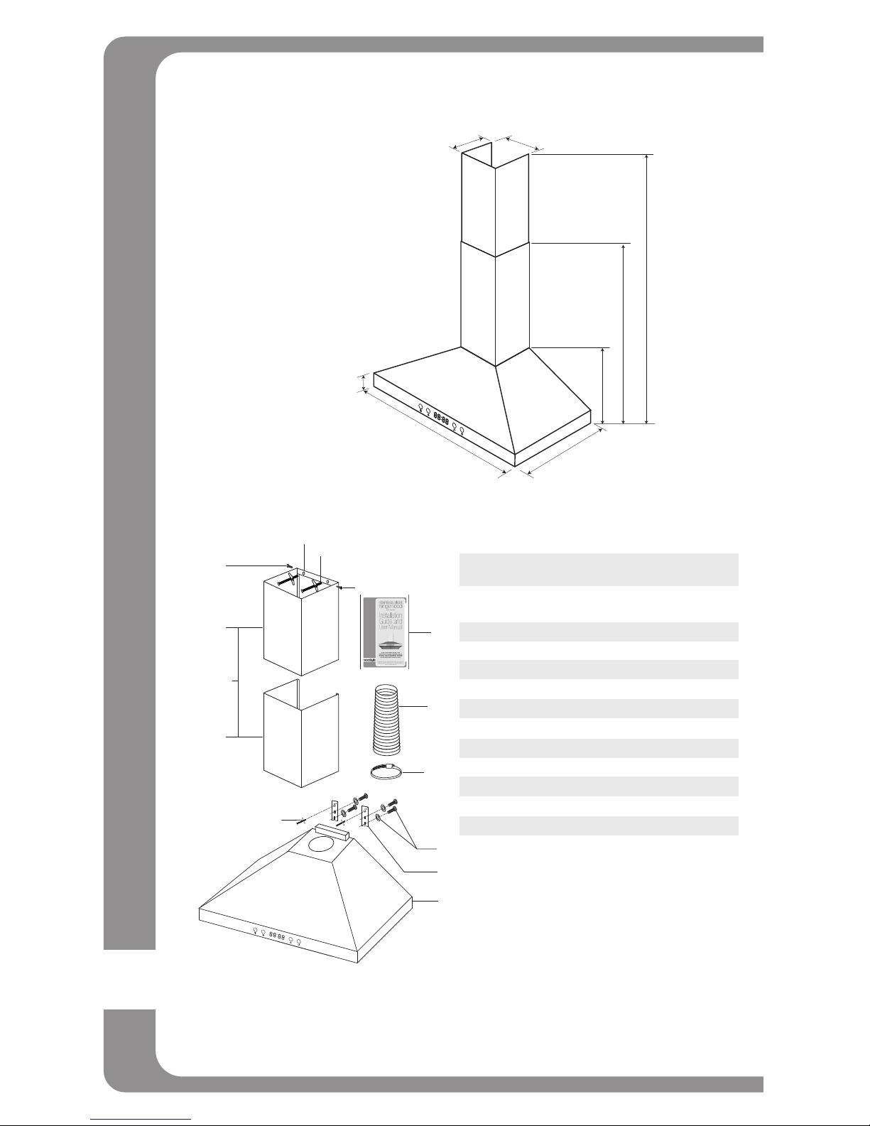
DIMENSIONS
750 mm
(29.5 in)
222 mm
(8.7 in)
220 mm
(8.7 in)
500 mm
(19.7 in)
50 mm (2 in)
260 mm
(10.2 in)
860 mm
(33.9 in)
1460 mm
(57.5 in)
PARTS
7
7
2a
2
2b
3
12
11
6
Part Qty Product Components
1 1 Hood body, complete with: controls, lights,
blower, filters, damper
2 1 set Telescopic Chimney
2a 1 Upper Chimney
2b 1 Lower Chimney
3 1 Aluminum Exhaust Duct
5 2 Hood brackets
6 1 Chimney support bracket
7 2 M4 x 8mm Tapping Screws
9 4 Toggle Bolts
10 4 M5 x 16mm Screw/Washer
11 1 Duct Clamp
12 1 Instruction Manual
9
1
5
10

11
Parts Bag
Aluminum
Exhaust Duct
Hood Body x 1 Installation
Guide x 1
M4 x 8mm
Tapping Screws
x 2
Duct Clamp
x 1
Toggle Bolts
x 4
M5 x 16mm
Screw/Washer
x 4 Sets
Hood
Brackets
x 2
Chimney Support
Bracket x 1
Duct Cover
x 1 set
WARNING
* Proper installation is your responsibility - Have a qualified technician install this range hood.
* Read the entire installation guide and user manual thoroughly, and understand instructions and warnings.
* PERSONAL INJURY HAZARD - Because of the weight and size of the range hood, two or more people
are needed to move and safely install the range hood. Failure to properly lift range hood could result in
damage to the product or personal injury.
* All openings in ceiling and wall where range hood will be installed must be sealed.
* Range hood location should be away from strong draft areas (windows, doors and strong heating vents).
* SEVERE INJURY - Rotating fan can cause severe injury. Stay clear of fan when motor is running.
* SEVERE INJURY - Range hood may have very sharp edges. Please wear protective gloves to remove
any parts for installing, cleaning or servicing.
NOTE:
• Before making cuts, make sure there is proper clearance within the ceiling or
wall for exhaust vent.
• Check your ceiling height and the hood height maximum before you select and
install your hood.
• The hood should be installed between 46 cm (18 in) and 75 cm (29.5 in) above
the counter top.
• Toggle bolts are provided to secure the hood to most wall types. However,
a qualied technician must verify suitability of the bolts, screws and drywall
anchors with your wall type.
• Put a thick, protective covering over your counter top, cook top or range to
protect from damage and dirt. Remove any hazardous objects around the area
when installing.
• Due to the size and weight of this range hood, the supports must be rmly
attached to the wall.
• For plaster or sheet rock walls, the support must be attached to the studs.
If this is not possible, a support structure must be built behind the plaster or
sheet rock. The manufacturer assumes no responsibility for injury or damage
caused by improper installation.
12
e. insTallaTion
NOTE: Carefully remove the plastic protective lm from all exterior sur-
faces of the hood and chimney prior to nal installation.
NOTE: At least two people will be required to mount the hood.
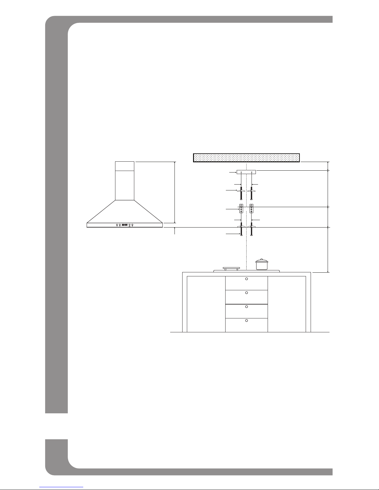
WALL DRILLING AND BRACKET INSTALLATION
1. Draw a vertical line on the supporting wall up to the ceiling, or as
high as practical, at the centre of the area in which the hood will be
installed.
5 cm
(2 in)
Part # 6
Part # 5
Part # 9
18.6 cm
(7.3 in)
13.6 cm
(5.36 in)
Min. 2 cm (0.8 in)
28.4 cm
(11.2 in)
46-75 cm
(18 - 29.5 in)
YX
Part # 9
2. Draw a horizontal line at 46 cm (18 in) above an electric stove or 75
cm (29.5 in) above a gas stove.
3. Place chimney support bracket (Part# 6) on the wall as shown about
2 cm (0.8 in) from the ceiling or upper limit aligning the centre (notch)
with the vertical reference line.
4. Mark the wall at the centre of the holes in the bracket.
5. Place the hood brackets (Part# 5) on the wall as shown aligning the
center notches to the vertical reference line.
6. Mark the wall at the center of the holes in the bracket.

13
7. Drill pilot holes at the center points of the top bracket (Part #6) and
the center points of the 2 hood brackets (Part #5).
8. Screw the 4 toggle bolts (Part #9) into wall leaving the head of the
bolts approximately 6.4 mm (0.25 in) away from the wall surface.
WALL
6.4 mm
(0.25 in)
WARNING
Because of the weight and size of the range hood,
two or more people are needed to move and safely
install the range hood. Failure to properly lift range
hood could result in damage to the product or
personal injury. Hood may have very sharp edges.
Please wear protective gloves if it is necessary to
remove any parts for installation.
PERSONAL INJURY HAZARD
MOUNTING THE HOOD BRACKETS
1. Attach the 2 hood brackets (Part #5) to the back of the hood body
with 4 screws and washers (Part #10).
Part# 1
Part# 5
Part# 10
DAMPER INSTALLATION
The dampers are installed at the factory. If they have come loose dur-
ing shipping, the following is how to replace them. Caution: Edges are
sharp. Wear safety gloves. Insert one end of the damper into the hinge
slot at the top of the hood body. Gently bend the damper and carefully
insert the second end of the damper into the hinge slot. Be very careful
when installing the dampers. Applying to much force or not bending the
damper enough may damage or break the damper hinge ends.

14
ATTACHING ALUMINUM DUCT
1. Place the aluminium duct clamp through one end of the aluminum
duct and slide it down over the damper assembly.
2. Tighten the screw on the duct clamp until tight.
3. Seal all joints with duct tape
CAUTION
This edge is sharp.
Wear safety gloves
ATTACHING HOOD BODY TO WALL
1. CAUTION: At least 2 people are required to lift and install this
range hood. Lift the hood body (Part #1) into position engaging
the 2 brackets (Part #5) with the 2 lower toggle bolts (Part #9).
CAUTION: Make sure the range hood is securely fastened to the
wall before releasing.
2.
Connect the duct to the exterior exhaust system. Make sure all joints are
secure and airtight. Use duct tape to make all joints secure and airtight.
3. Remove the plastic covering on the chimney extensions (duct
covers). Be very careful of sharp edges on the chimneys. Wear
protective gloves while installing duct cover to prevent personal injury
and prevent scratches on cover during installation
4. Place the chimney extensions on the oor, then lower the upper
chimney into the lower chimney. You should now have both chimney
extensions together as one unit.
upper
chimney upper
chimney
lower
chimney
lower
chimney
15
5. Place the chimney onto the hood body, ensuring it ts into the gap
on the top of hood body.
6.
Slide the chimney extensions upward and secure the upper chimney to
the chimney support bracket using two 4 mm x 8 mm tapping screws.
CAUTION: Minimize movement of the chimney extensions to avoid
scratches.
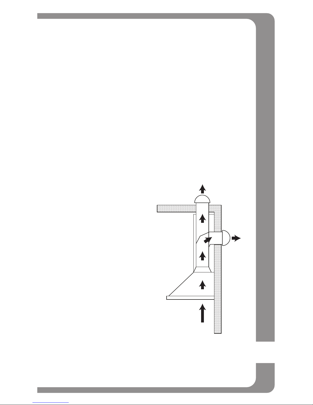
EXHAUST VENTING
Ducted mode air exhaust system
Caution: To reduce the risk of re, use metal duct work only.
1. Decide where the duct work will run
between the hood and the outside.
2.
A straight, short duct run will allow the
hood to perform most efciently.
3. Long duct runs, elbows, and
transitions will reduce the performance
of the hood. Use as few of them
as possible. Larger ducting may be
required for best performance with
longer duct runs.
4.
Attach an adequate length of 15 cm
round duct to the air outlet adapter
(Not supplied).
5. The air must not be discharge into a
ue that is used for exhausting fumes
from appliances burning gas or other
fuels. Follow all regulations concerning
the discharge of air.
6. Install a roof/wall cap. Connect round
metal duct work to cap and work back
towards hood location. Use duct tape
to seal the joints between duct work
sections.
16
ELECTRICAL CONNECTION
Electrical wiring must be done by a qualied person(s) in accordance
with all applicable electrical and building codes. Turn off electrical power
at the power source before wiring.
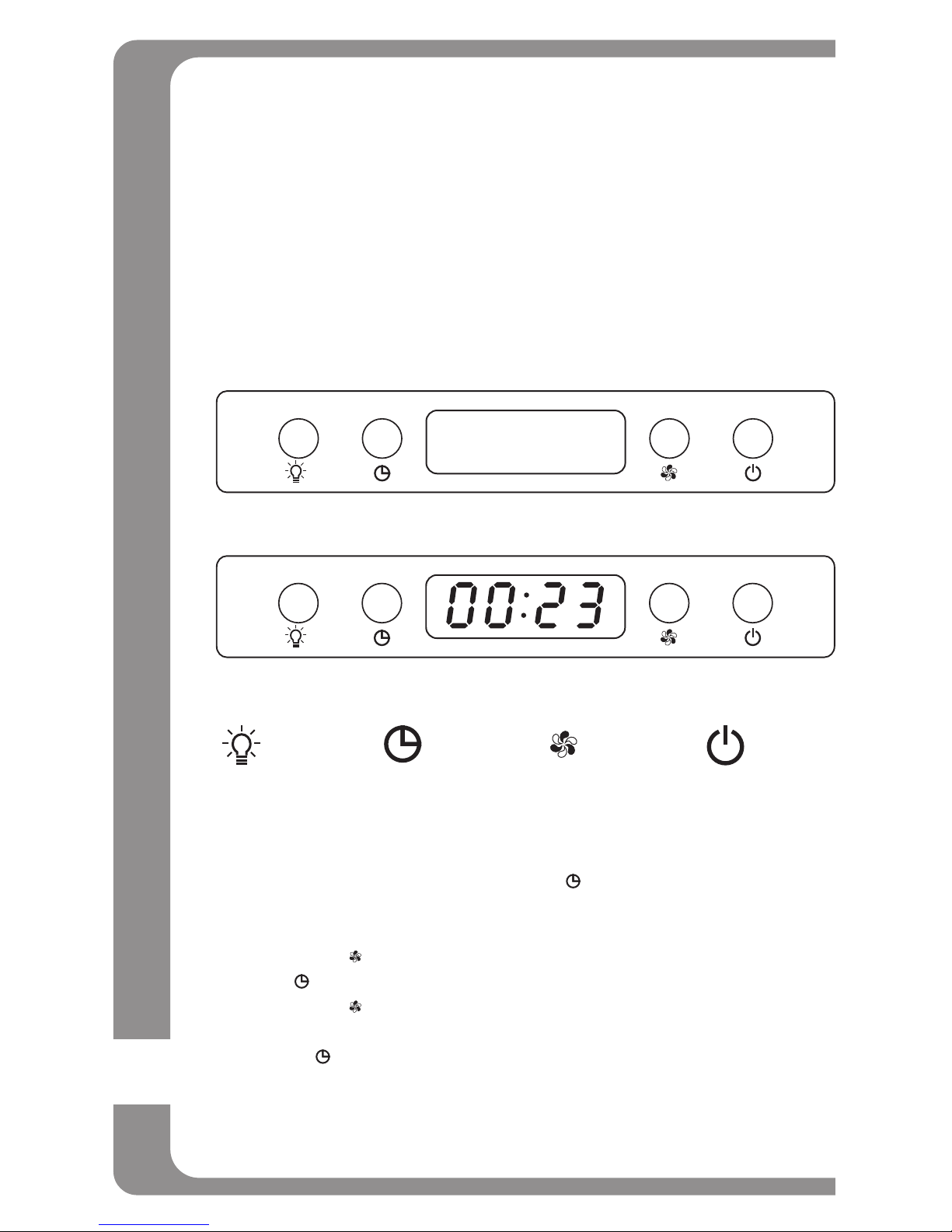
CONTROL PANEL
The LED screen and switches appear and function as shown below.
Please refer to specic function instructions for information on how to
use the range hood’s various features.
In stand-by mode
In use
LIGHT CLOCK SPEED ON/OFF
24 HOUR CLOCK SETTING
1. When the range hood is plugged in for the rst time, the entire
screen will ash for 2 seconds, then only the clock (00:00) will ash.
2. To set the time, press and hold the “ ” for more than 2 seconds
until the rst set of 00’s start to ash.
(00:00 = Hour : Minute, it is 24 hour setting)
3. Press the “ ” to change the hour. Once the hour is correct, press
the “ ” and the second set of 00’s will ash.
4. Press the “ ” until the desired minutes appear. This is a 24 hour
clock where 00:00 = Hour : Minutes.
5. Press “ ” again to conrm the time setting. If during the setup
process no button is pressed for more than 5 seconds, the clock
will revert to the previous time setting.

17
FAN OPERATION
1. Press the “ ” to start the blower. The blower will start on the high
speed setting.
2. Press the “ ” again to turn the fan to low speed.
3. Press the “ ” twice to turn off the range hood fan. This will not turn
off the light, if the lights is on, press the “ ” once.
DELAY SHUT-OFF
1. With the fans running, press the “ ” once.
2. Set the delay time using the same procedure as setting the clock.
3. Once the correct delay time is set, press the “ ” to commence the
timer count down.
4. When the timer reaches 00:00, the blower will stop and the system
will beep 1 time.
5. To cancel the delay shut-off during count down, press the “ ”
once.
NOTE: The delay shut-off will only turn off the blower. If the lights are
on they will remain on after the timer reaches 00:00 and the fan shuts
down. The fan MUST be running to start the delay shut-off feature.
LIGHT “ ”
1. When the light is off, press the “ ” briey to turn on the lights.
2. When the light is on, press the “ ” briey to turn off the lights.
MainTenance
Prior to any maintenance operation ensure that the range hood is discon-
nected from the power supply.
Cleaning Exterior Surfaces:
- The range hood should be cleaned regularly internally and externally.
- Clean periodically with hot soapy water and clean cotton cloth. Do not
use corrosive or abrasive detergent (e.g. Comet Power Scrub , EASY-
OFF oven cleaner), or steel wool/scoring pads, which will scratch and
damage the stainless steel surface.
- For heavier dirt use a liquid degreaser.
- After cleaning, you may use a non-abrasive stainless steel polish/
cleaner to polish and buff out the stainless luster and grain. Always
rub lightly with a clean cotton cloth, and go with the grain.

18
Cleaning Aluminum Grease Filter/Stainless Steel Filter-less Grill:
- The metal lters tted by the factory are intended to lter out residue
and grease from cooking. It need not be replaced on a regular basis
but must be kept clean.
- This must be cleaned once a month using non-abrasive detergents,
either by hand or in the dishwasher, which must be set at a low
temperature on a short cycle.
- When washed in a dishwasher, the grease lter may discolour
slightly, but this does not affect its ltering ability.
- Dry lters and re-install before using hood.
WARNING: FAILURE TO CARRY OUT THE BASIC STANDARDS
OF CLEANING OF THE RANGE HOOD AND REPLACEMENT
OF THE FILTERS MAY CAUSE FIRE RISKS. WE THEREFORE
RECOMMEND THAT YOU FOLLOW THESE INSTRUCTIONS.
Replacing Filters:
- Should lters wear out due to age or prolonged use, replace with an
aluminum grease lter (with stainless steel clips).
- Note: Also replace a damaged lter that has punctures or a bent or
broken frame.

19
REPLACING LIGHT BULBS:
WARNING: DISCONNECT RANGE HOOD FROM ELECTRICAL
SOURCE AND BE SURE LIGHTS ARE COOL.
WARNING
BURN HAZARD
Light bulbs can become extremely hot when turned on. DO NOT touch bulb until switched off and cooled.
Touching hot bulbs could cause serious burns.
SEVERE INJURY
Rotating blower fan can cause severe injury. Stay clear of fan when motor is running.
Should the light bulb burn out due to age or prolonged use, replace
with MAX. 35W/JDR 16, GU10 twist and lock base lamps.
If new lights do not operate, make sure the light bulb is inserted correctly.
1. Turn off the range hood.
2. Ensure the lights are cool to the touch.
3. Turn bulb anti-clockwise to remove.
4. Install a new GU10 twist and lock base lamp (MAX. 35W/JDR 16)
and turn clockwise to install the light bulb. Do not release the bulb
until you are sure the bulb has been securely installed.
Rotate clockwise
and push in to install
Rotate anti-clockwise
and pull out to remove

20
TroubleshooTing
1. If the range hood does not operate after installation:
- Check if all power has been turned back on and all electrical wiring
is properly connected.
- Check that the power connection for the unit is properly connected.
- Make sure the wiring between the switch board and control board
are connected properly.
2. The range hood vibrates when the blower is on:
- The range hood might not have been secured properly to the wall.
- Check if the motor is secured in place. If not, then tighten the motor
in place.
- Check if there is a damaged blower wheel. If so, change the blower
wheel.
3. The blowers seems weak:
- Check that the duct size used is at least 15.2 cm (6 in.). Range
hood WILL NOT function efciently with insufcient duct size.
- Check if duct is clogged or if damper unit is not opening properly. A
tight mesh on a side wall cap unit might also restrict air ow.
4. The lights work but the blower is not spinning, is stuck or is
rattling:
- The blower might be jammed or scraping the bottom.
- The motor is defective, possibly seized - change the motor.
- The thermal protection system detects if the motor is too hot to
operate and shuts the motor down. In this case the motor will
function properly after the thermal protection system cools down
(approx. 20 min.).
5. The hood is not venting properly:
- Make sure the distance between the cook top and the bottom of
the hood is between 46 cm (18 in) for electric ranges and 75 cm
(29.5 in) for gas ranges.
- Reduce the number of elbows and length of duct work. Check if
all joints are properly connected, sealed and taped.
- Make sure the power is on high speed for heavy cooking.
- Wind from opened windows or doors in the surrounding area are
affecting the ventilation of the hood. Close all windows and doors
to eliminate the outside air ow.
- Check if the direction of duct opening is against the wind. If so,
adjust the direction of the duct opening.
- Check if the wrong size of ducts are being used.
Table of contents
Other nexstyle Ventilation Hood manuals


Popular Ventilation Hood manuals by other brands


Maico
Maico ER 60 VZ 15 Mounting and operating instructions

Imperial Kitchen Ventilation
Imperial Kitchen Ventilation WH1900 Series Installation instructions & warranty information

TSI Instruments
TSI Instruments ALNOR LOFLO BALOMETER owner's manual

Amica
Amica OKC651S instruction manual

NEFF
NEFF D76E21N0GB installation instructions

FALMEC
FALMEC EXPLOIT Instruction booklet


