Installaon instrucons for the IMM'Ax automac immersed safety cover - 6/36
66
2. Delivery and recepon of
the roller
2.1 Delivery
Fig. 6
- Plan the presence of 2 to 6 persons, or use a handling
device to handle the cover. The cover is delivered in a non-
recoverable wooden container measuring at least 40 cm
more than the width of the pool. It is heavy and fragile.
- For a 4 x 8 m pool, the container weighs 465 Kg and
measures 4.6 x 0.6 x 0.8 (h).
- For a 5 x 10 m pool, the container weighs 610 Kg and
measures 5.6 x 0.6 x 0.8 (h).
2.2 Recepon
- Open the container in the presence of the delivery staff
and check the condion of the goods and their compliance.
Keep the original packing.
- If there is any damage or missing parts, write down your
reserves on the transport documents (e.g.: container
open on delivery). The words "subject to unpacking"
alone are null and void. Send a registered letter (with
acknowledgement of receipt) to the transporter within
2 days. This letter must give an exact description of
the damage. Send a copy of the letter to AS POOL for
informaon.
- Store the parts in the container which should not be le
in full sunlight, but should be placed in a cool place if the
assembly is not carried out on the same day.
- Make the inventory compared to the order.
- Read the instructions completely before starting the
assembly.
- The installaon requires 2 persons for 7 hours.
2.3 Items in the container
- A slat apron
- A motorised roller sha
-Twoflanges to support the sha
- A 23 x 32 cm box
- A slaed cover made up of a beam and duckboards (if
ordered).
- A paron wall (if ordered).
-Afixture kit
- Installaon instrucons
x 2 07:00
Fig. 6
0.8m
x
0.6m
Lx
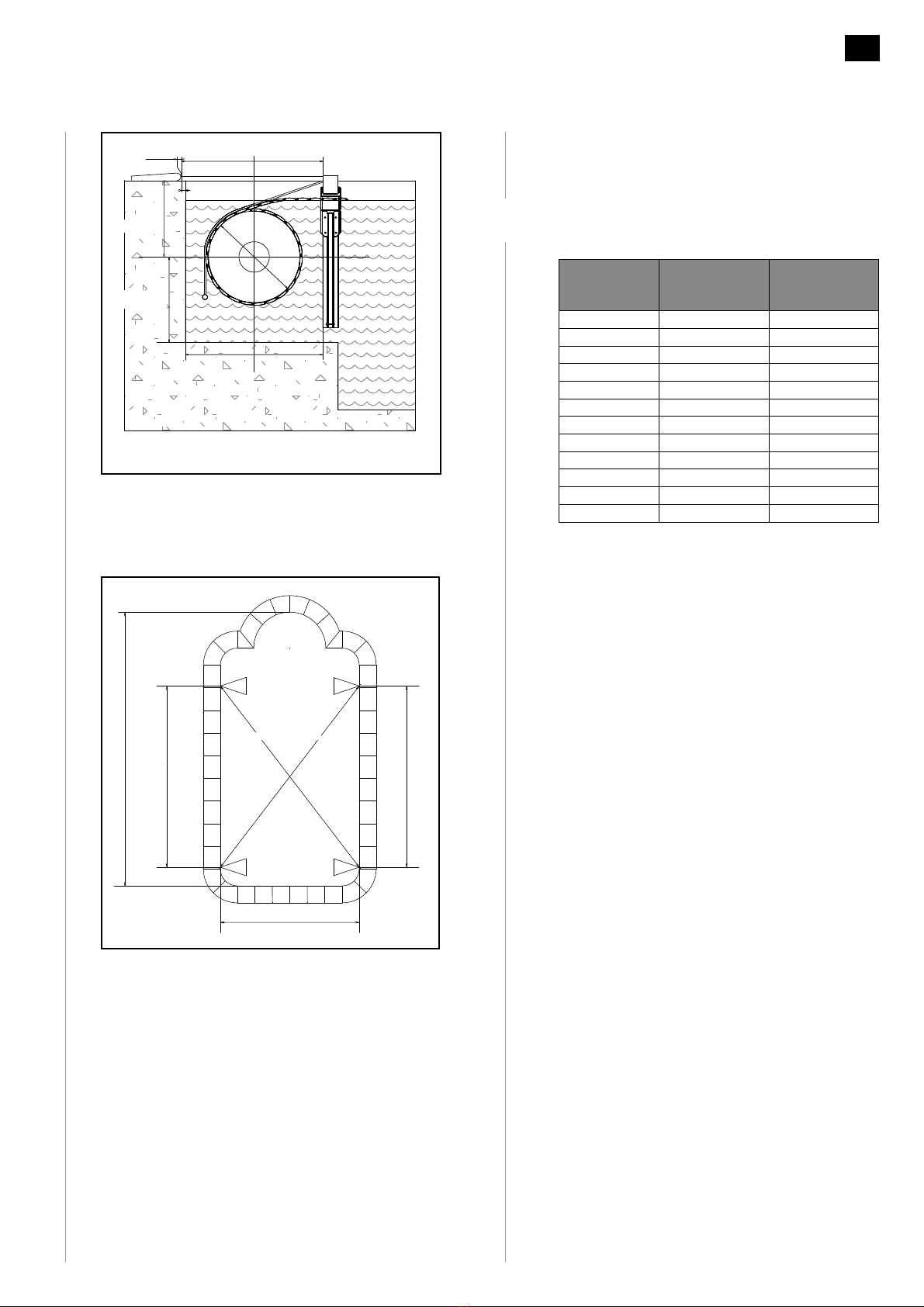
4 290
5 300
6 310
7 320
I4.2 4.7 5.2 6.2 7.2 8.2 9.2 10.2 11.2 12.2
X4.6 5.1 5.6 6.6 7.8 8.6 9.6 10.6 11.6 12.6
0.6 m
0.8 m
x