Acclaim Lighting Unity SNS2019 User manual

www.acclaimlighting.com Unity™
User guide


1
CONTENTS
INTRODUCTION ....................................... 3
Welcome 3
Safety, maintenance and cleaning 3
Supplied items 4
Optional extras 4
Outdoor Linking System part codes 7
INSTALLATION.......................................... 8
Mounting the unit 8
Using a tenon mount 9
Using a pipe clamp 10
Using an extender bar 11
Fitting a pendant mount set 12
Fitting an aircraft cable mount set 15
Fitting a snoot 18
Power cabling 19
Wired DMX control 20
Input wiring protection (AJBOX1) 21
Cabling with OLS 23
Wireless DMX control 25
CONFIGURATION.....................................26
Removing the display cover 26
Entering the menu 26
Menu navigation 27
Setting the DMX address 29
Returning to factory settings 29
Viewing fixture information 29
Selecting the channel mode 30
Determining solo behavior 31
Setting an internal color 31
Fan mode 31
Color calibration 32
Using the automation features (Photocell) 32
Adjusting the gamma setting 33
Adjusting the PWM frequency 33
Changing the display settings 34
Running a system test 35
Setting a white balance 35
Configuring Aria wireless DMX 36
Unity configuration via RDM 37

3
INTRODUCTION
WELCOME
Welcome to Unity™ from Acclaim Lighting. This rugged fixture brings new levels of flexibility,
performance and refinement to exterior illumination. The Spectrum Five light engine
(red, green, blue, amber and lime) offers exceptional
brightness and clarity. In addition to RGBAL saturated
color mixing, a specially calibrated CCT control channel
allows you to dynamically configure any color temperature of white, from a warm 2500K
right up to an ultra cool 8000K. The advanced 7.5”polymer fresnel lens ensures the
10-degree native beam is fully homogenized and totally free of color striations.
External control using DMX-512A is supported either through direct cable connection or via
the built-in Aria™ wireless DMX receiver (transmitter available as an optional extra).
A clear daylight-readable OLED touch-screen user display provides access to a
comprehensive configuration menu system (see page 26). Alternatively, the industry
standard RDM (Remote Device Management) format can be used to configure numerous key
settings without the need to visit each fixture (see page 37).
For standalone applications, Unity provides an automation feature which will output a
predetermined color/white mix as the ambient light falls below a certain level, paired with
a configurable timer for auto shut off. The internal auto-sensing power supply can accept
mains inputs between 100 to 277VAC at 50 or 60Hz.
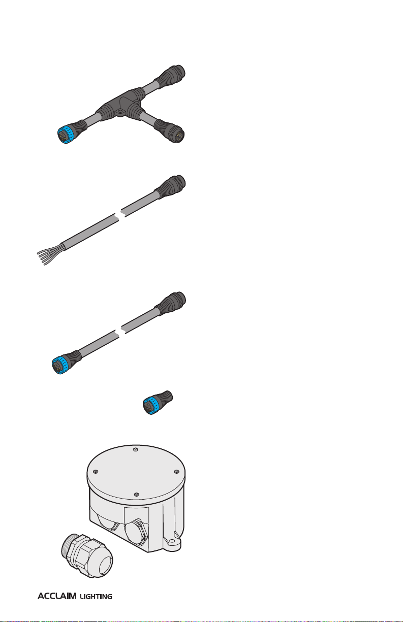
Each Unity fixture is supplied with a detachable 9’
(2.7m) control/power input cord (with bare-wire tails).
The corresponding input socket on the Unity rear
panel is also directly compatible with the Outdoor Link System, which greatly simplifies the
task of distributing power and control to multiple fixtures (see page 23).
A full range of mounting, suspension, connection and light shaping options are available to
allow Unity to easily adapt to the needs of any installation (see from page 4).
SAFETY
•When fixtures are mounted off-ground, ensure they are securely fitted to an appropriate
mounting surface.
•Ensure that the power input is supplied from a correctly fused, earthed and
environmentally protected location.
MAINTENANCE
CAUTION: Always isolate mains power before starting maintenance operations.
•Ensure that all mounting (and device) screws/bolts are fully tight and free of corrosion.
•Ensure there is no deformation to the housing, lenses or fixing points.
•Check that all power supply cables are free from physical damage or material fatigue.
•Use only genuine spare parts supplied by Acclaim Lighting.
CLEANING
•Use a moist, lint-free cloth when cleaning each fixture.
•Never use alcohol or solvents.
SAFETY, MAINTENANCE AND CLEANING
OUTDOORLINK
SYSTEM

4
SUPPLIED ITEMS
OPTIONAL EXTRAS
Unity
Supplied with integral mounting yoke and
detachable 9 foot (2.7m) combined power and
control tail. Optional Outdoor Linking System feed
cables are directly compatible - see page 7.
Half snoots
Gray [UNAHSG]
Black [UNAHSB]
White [UNAHSW]
Custom* [UNAHSC]
Full snoots
Gray [UNAFSG]
Black [UNAFSB]
White [UNAFSW]
Custom* [UNAFSC]
* RAL # also required

5
OPTIONAL EXTRAS (CONTINUED)
Tenon mounts
For use with Schedule 40 pipe: 2.51”
and 4.13” inner diameter respectively.
2” pole 4” pole
Gray [TM2G] [TM4G]
Black [TM2B] [TM4B]
White [TM2W] [TM4W]
Custom* [TM2C] [TM4C]
Pipe clamps
For use with Schedule 40 pipe: 2.51” and
4.13” inner diameter respectively.
(polished aluminum finish)
2” pipe [PC2]
4” pipe [PC4]
Extender arms
Fixture bolts and washers plus cable access seal included
1’ 2’ 3’
Gray [OFLEB1G] [OFLEB2G] [OFLEB3G]
Black [OFLEB1B] [OFLEB2B] [OFLEB3B]
White [OFLEB1W] [OFLEB2W] [OFLEB3W]
Custom* [OFLEB1C] [OFLEB2C] [OFLEB3C]
* RAL # also required

6
OPTIONAL EXTRAS (CONTINUED)
Pendant mount set
Includes ceiling mount and replacement fixture yoke.
NPS pipe required (see below).
Gray [UNAPMSG]
Black [UNAPMSB]
White [UNAPMSW]
Custom* [UNAPMSC]
NPS pipe
One length required to accompany a pendant mount set
(1” NPS, OD=1.315”).
12” 24” 36”
Gray [UNANPS1-12G] [UNANPS1-24G] [UNANPS1-36G]
Black [UNANPS1-12B] [UNANPS1-24B] [UNANPS1-36B]
White [UNANPS1-12W] [UNANPS1-24W] [UNANPS1-36W]
Custom* [UNANPS1-12C] [UNANPS1-24C] [UNANPS1-36C]
* RAL # also required
Aircraft cable mount set
Includes ceiling mount and replacement fixture yoke.
Stainless steel cable required (see below).
Gray [UNAAMSG]
Black [UNAAMSB]
White [UNAAMSW]
Custom* [UNAAMSC]
Stainless steel cable
One length required to accompany an aircraft cable mount set.
2’ 5’ 10’
[UNAAC2] [UNAAC5] [UNAAC10]
* RAL # also required

7
IP66 junction box plus
outlet cable gland
See page 21
[AJBOX1]
OUTDOOR LINKING SYSTEM PART CODES
Feed cables
1’ (30cm) [OLSF1]
5’ (1.5m) [OLSF5]
10’ (3m) [OLSF10]
25’ (7.6m) [OLSF25]
50’ (15.2m) [OLSF50]
T-junction
[OLST]
Terminator
[OLSEC]
Link cables
1’ (30cm) [OLSL1]
5’ (1.5m) [OLSL5]
10’ (3m) [OLSL10]
25’ (7.6m) [OLSL25]
50’ (15.2m) [OLSL50]

8
INSTALLATION
MOUNTING THE UNIT
Each Unity fixture includes a sturdy
yoke mount with multiple holes in its
base for various fixing options. The
Unity fixture weighs 26.9 lbs (12.2 kg)
- ensure that the mounting surface
and the fixings used are sufficiently
rated for the task (including wind
shear forces).
Safety wire
anchor point
A safety wire anchor point is located on
the underside of the Unity xture to allow
attachment to a sturdy secondary xing
point, where necessary.
The yoke adjusters on each side of Unity
require a 5/16”(8mm) Allen (hex) wrench
to focus the fixture. Loosen the pivot bolt
on each side and gently pull apart the yoke
arms to allow the fixture body to rotate.
Release the yoke arms and tighten the bolts
when the required tilt angle is achieved.
A useful angle chart is provided on each
side to assist with initial adjustment.
Use a 5/16”
(8mm) Allen
hex wrench
Angle chart
When installing each Unity fixture, ensure the surface is level and that nothing is protruding
to damage the mounting yoke. The yoke has multiple mounting holes and is suitable for
mounting directly onto steel, aluminum, concrete or wood structures. Bolts or screws (not
supplied) should be suitable for the surface (and the weight of the fixture, plus safety factor)
and ensure a secure mount for the fixture.

9
USING A TENON MOUNT
Optional tenon mounts are available for use when Unity needs to be mounted on top of
a vertical pole. Tenon mounts are available for use with 2” and 4” (Schedule 40) poles of
sufficient rigidity for the weight of the fixture.
IMPORTANT: Tenon mounts are
suitable only for vertical pole
mounting where the xture sits on
top of the pole. Tenon mounts must
NEVER be used to hang a Unity
xture below a pole. For pendant-
type installations, use the pendant
mount set (see page 12).
TO USE A TENON MOUNT
1 Slide the tenon mount onto the
vertical pole and tighten the two
bolts on the side using a 1/4”(6mm)
Allen (hex) wrench.
2 Secure the Unity yoke to the tenon
mount using the supplied main bolt
and partially tighten using a 11/16”
(17mm) A/F wrench. Rotate the
fixture to the required position and
insert the pan control bolt - tighten
using a 1/4” (6mm) Allen (hex)
wrench. Fully tighten the main bolt.
3 Secure the feed cable neatly and
securely down the pole.
Main
bolt
Pan
control
bolt
Pole
bolts
Schedule
40 pipe

10
USING A PIPE CLAMP
Optional pipe clamps are available to mount Unity fixtures on either 2”(50mm) or 4”
(100mm) (Schedule 40) tubes and poles.
IMPORTANT: Ensure the pipe (Schedule 40) and its mountings have sucient load
capacity for the Unity xture(s) to be mounted.
TO USE A PIPE CLAMP
1 Separate the two halves of the clamp, if they are already bolted together.
2 Place the two halves of the clamp around the pipe.
3 Use the two longer bolts,
one from each side to join
the two halves - see below
about the correct use of the
supplied washers.
4 Tighten the two main bolts
evenly until the clamp is
held firmly in place.
5 Use the two smaller bolts
(with spring and standard
washers) to fix the Unity
yoke to one side of the
clamp and tighten.
6 Secure the feed cable neatly
and securely along the pole.
(2 o)
M10 x 50mm
Using the supplied washers
The supplied spring washers
help to maintain tension on the
bolts to prevent loosening.
Always place the spring
washer on each bolt
first and then add
the standard washer,
before inserting the
bolt into the clamp.
This will prevent the
steel spring washer
from denting the softer
aluminum body of the
clamp.
(2 o)
M10 x 25mm
Schedule
40 pipe

11
USING AN EXTENDER BAR
Optional extender bars in various lengths (see page 5 for part numbers and page 50
for dimensions) are available to allow each Unity fixture to be held a certain distance from a
vertical mounting surface.
Each extender bar is manufactured entirely from aluminum to minimize weight and is
supplied with two sets of bolts, spring washers and standard washers to secure the fixture
swivel mount base (see note below).
There are four Ø7/16” (Ø11mm) holes in the backplate to allow for secure attachment to the
mounting surface. Wall screws are not provided; ensure the ones used are suitable for the
wall surface and have sufficient tensile strength for the combined weight and leverage of
the fixture plus the bar.
CONCEALED CABLING
Each extender bar features an access
hole on the top to allow power/control
cord access through the hollow bar
and backplate into the wall surface. A
waterproof seal for the cable access
hole is also provided.
Using the supplied washers
The supplied spring washers
help to maintain tension on the
bolts to prevent loosening.
Always place the spring
washer on each bolt
first and then add the
standard washer, before
inserting the bolt into
the clamp. This will
prevent the steel spring
washer from denting
the softer aluminum
body of the yoke.

12
FITTING A PENDANT MOUNT SET
IMPORTANT: The pendant mount requires a solid, weight-bearing horizontal
mounting surface. You also need to source mounting hardware appropriate to the
mounting surface, rated to safely hold the weight of the total xture plus safety
factor. If the power/control cord will be fed up through the pole, a hole will also need
to be made through the mounting surface to accommodate the cord.
TO FIT A PENDANT MOUNT SET
1 Remove the existing yoke from the Unity fixture:
•Lay down a protective surface, such as a thick
blanket or the foam insert from the Unity box,
and place the Unity fixture face down on the
surface.
•Use a 5/16”(8mm) Allen (hex) wrench to
remove the large pivot bolt from each side of
the yoke.
•Gently pull the arms of the yoke out from the
fixture body so that the pivot points disengage
- thus freeing the yoke from the fixture body.
2 Transfer the two pivot cups from the original yoke
to the new pendant yoke:
•Use a #2 Phillips driver to remove the three
screws holding each pivot cup to the arms of
the original yoke.
•Using the removed screws, attach each pivot
cup to the outside of the arms of the new
pendant yoke.
3 Separate the top bracket from the new pendant
yoke:
•Use a 3/16”(4mm) Allen (hex) wrench to
remove the two bolts (A) that lock the NPS pipe
in place within the top bracket.
•Use a 1/8”(3mm) Allen (hex) wrench to remove
the two small bolts (B) that secure the cover
plate to the top bracket.
•Slide down the cover plate and unscrew the top
bracket from the NPS pipe. Tip: Keep the cover
plate safely in place on the NPS pipe.
Pivot
bolt
A
A
B
B
Cover
plate
Top
bracket
Pivot cup

13
4 Attach the new pendant yoke to the Unity fixture body:
•Place the new pendant yoke over
the Unity fixture body and gently
pull the arms of the yoke out a little
so that the pivot cups can correctly
mesh with the corresponding
pivots of the fixture.
•Insert the large pivot bolts on
each side of the yoke and use a
5/16”(8mm) Allen (hex) wrench to
tighten them.
5 Attach the top bracket securely to the ceiling:
•Use two fixings (appropriate for the weight of the
Unity fixture and the mounting surface) to securely
attach the top bracket.
•Note: When the NPS pipe is fitted to the top bracket and
correctly secured with the two locking bolts, the pendant
yoke will always become aligned with the axis of
the top bracket’s two mounting slots (see right). This
becomes important if the Unity fixture will need to
be tilted to illuminate in a particular direction. If the
fixture will point straight down then the top bracket
orientation is not a limiting factor.
•Note: If the power cord is to be fed up through the
NPS pipe, first drill a hole in the mounting surface
that will lie at the center of the top bracket position.
However, do not yet plug the cord to the input
socket on the Unity fixture.
•See page 49 for top bracket dimensions.

14
7 Complete the installation:
•Carefully feed the power/control cord up through the
yoke , NPS pipe and top bracket into the mounting
surface hole and ceiling space above.
•Raise up the cover plate and align it with the two
small holes in the underside of the top bracket.
•Insert the two small bolts (B) removed earlier and
tighten.
•Insert the two larger bolts (A) into the top bracket
holes that are either side of the NPS pipe. It is
important that the corresponding holes in the NPS
pipe align with these holes and the bolts are fully
engaged.
•Plug the power/control cord into the socket on the
rear panel of the Unity fixture.
•If necessary, tilt the fixture to the required angle by
loosening the pivot bolts.
6 Attach the pendant assembly (the NPS pipe, pendant yoke and Unity fixture) to the top
bracket.
•With assistance from a co-worker, lift up the pendant
assembly to the top bracket.
•Carefully engage the screw thread of the NPS pipe
with the top bracket and rotate the pendant assembly
clockwise to fully engage the thread.
•Keep rotating the pendant assembly until the two
holes either side of the top bracket align with the
corresponding holes in the NPS pipe.
A
A
B
B

15
FITTING AN AIRCRAFT CABLE MOUNT SET
IMPORTANT: The aircraft cable mount requires a solid, weight-bearing horizontal
mounting surface. You also need to source mounting hardware appropriate to the
mounting surface, rated to safely hold the weight of the total xture plus safety
factor. If the power/control cord will be fed up through the top bracket, a hole will
also need to be made through the mounting surface to accommodate the cord.
TO FIT AN AIRCRAFT CABLE MOUNT SET
1 Remove the existing yoke from the Unity fixture:
•Lay down a protective surface, such as a thick
blanket or the foam insert from the Unity box,
and place the Unity fixture face down on the
surface.
•Use a 5/16”(8mm) Allen (hex) wrench to
remove the large pivot bolt from each side of
the yoke.
•Gently pull the arms of the yoke out from the
fixture body so that the pivot points disengage
- thus freeing the yoke from the fixture body.
2 Transfer the two pivot cups from the original yoke
to the new cable mount yoke:
•Use a #2 Phillips driver to remove the three
screws holding each pivot cup to the arms of
the original yoke.
•Using the removed screws, attach each pivot
cup to the outside of the arms of the new cable
mount yoke.
Pivot
bolt
Pivot cup
3 Release the cover plate from the top bracket of the
new mount:
•Use a 1/8”(3mm) Allen (hex) wrench to remove
the two small bolts that secure the cover plate
to the top bracket.
•Slide the cover plate down the suspension
cable. Cover
plate
Top
bracket

16
5 Attach the Unity fixture body to the
new yoke:
•With assistance from a co-worker,
lift up the Unity fixture body to the
suspended yoke.
•Place the new yoke over the Unity
fixture body and gently pull the
arms of the yoke out a little so that
the pivot cups can correctly mesh
with the corresponding pivots of the
fixture.
•Insert the large pivot bolts on each
side of the yoke and use a 5/16”
(8mm) Allen (hex) wrench to tighten
them.
4 Attach the top bracket securely to the ceiling:
•Use two fixings (appropriate for the weight of the Unity
fixture and the mounting surface) to securely attach the top
bracket.
•Note: If the power cord is to be fed up through the top bracket,
first drill a hole in the mounting surface that will align with the
cord hole within the top bracket.
•See page 49 for top bracket dimensions.

17
6 Complete the installation:
•Feed the power/control cord up through the
rectangular hole in the cover plate, through the cord
hole in the top bracket and into the ceiling space.
•Raise up the cover plate and align it with the two small
holes in the underside of the top bracket.
•Insert the two small bolts removed earlier and tighten.
•Plug the power/control cord into the socket on the rear
panel of the Unity fixture.
•If necessary, tilt the fixture to the required angle by
loosening the pivot bolts.

18
FITTING A SNOOT
Snoots help to reduce or eliminate light spill into unwanted areas. The full and half snoots
available from Acclaim Lighting are attached to the Unity fixture in the same way.
Tip: Adding a snoot is made easier when the fixture’s front face is pointing vertically upwards.
1 Use a 1/8”(3mm) Allen (hex) wrench to remove the four bolts that secure the front ring
and remove the ring.
2 Remove the front ring and place the snoot onto the front of the fixture. The snoot
mounting holes must align with the same threads that are used by front ring. There are
also two slots either side of the snoot which must fit onto the small locating pins either
side of the fixture.
Full or half
snoot
3 Replace the front ring.
4 Tighten the bolts evenly.
Table of contents
Other Acclaim Lighting Lighting Equipment manuals

Acclaim Lighting
Acclaim Lighting Ai Flex Interior User manual

Acclaim Lighting
Acclaim Lighting Flex One Exterior Series User manual

Acclaim Lighting
Acclaim Lighting Pixel Bar User manual

Acclaim Lighting
Acclaim Lighting Linear XTR User manual

Acclaim Lighting
Acclaim Lighting Dyna Accent Mini User manual

Acclaim Lighting
Acclaim Lighting Flex Tube Mini User manual

Acclaim Lighting
Acclaim Lighting Flex Tube SC G2 User manual

Acclaim Lighting
Acclaim Lighting Flex Tube Pixel User manual

Acclaim Lighting
Acclaim Lighting Flood One EO Series User manual

Acclaim Lighting
Acclaim Lighting Aqua Graze User manual