6
4
31
2
AA
B1 B2
L
l
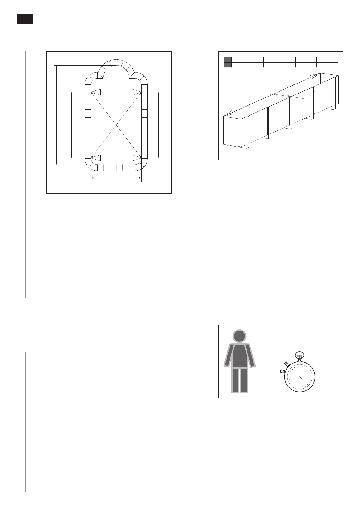
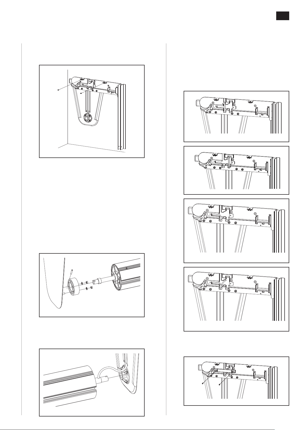
Once this test has been carried out and checked,
points 1 and 3 will be used as references to align
the sha to the pool. This posioning allows the
sha to be perfectly perpendicular to the length of
the pool.
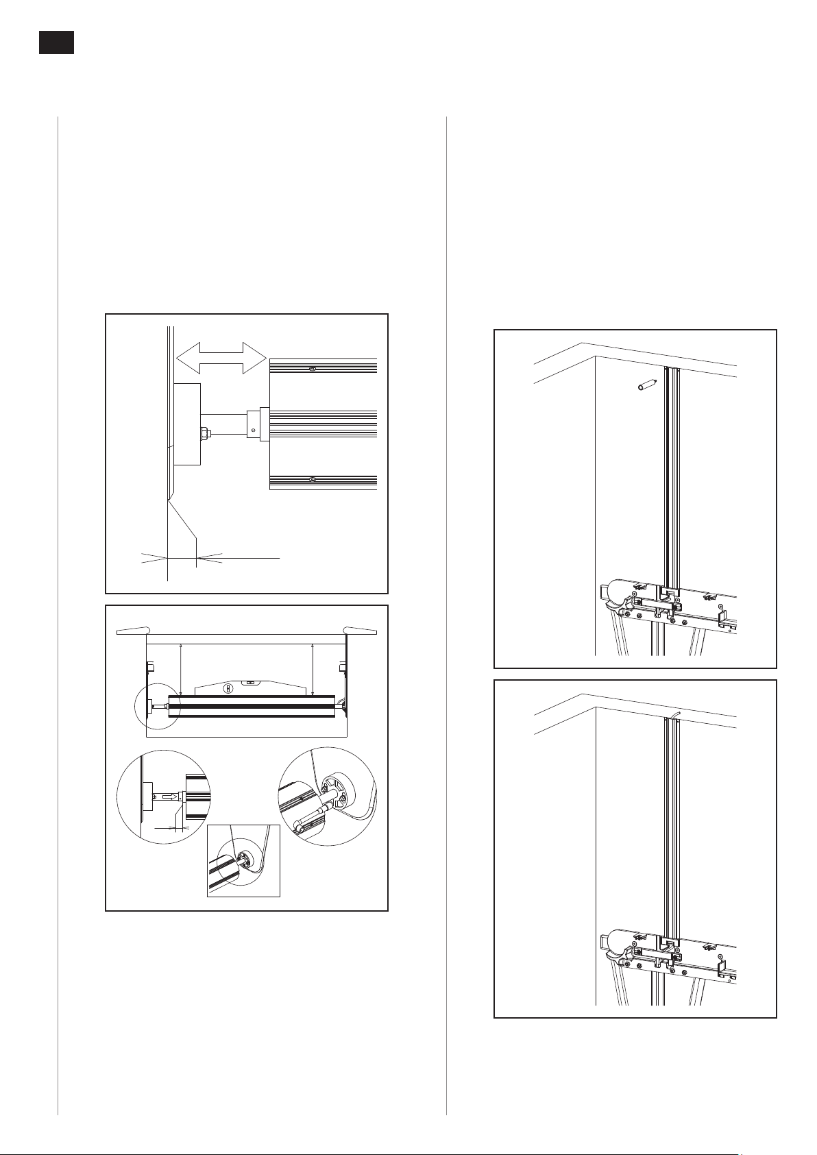
If the rear wall is not perpendicular to the width
of the length, the width of the passage slit will
not be regular but must be between 4 and 6 cm.
If necessary, the wall will have to be adjusted to
meet this condion.
Note: Cut the coping if your water level is too high
(less than 6 cm from the levelling course), because
the slats may rub against the coping during closure.
2. Delivery and recepon of
the roller
2.1 Delivery
-
-
-
0.8 m
x
0.6 m
l
X
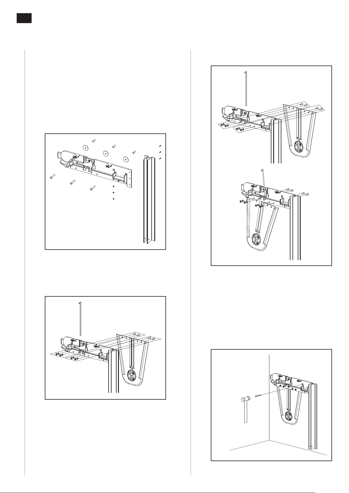
2.2 Recepon
-
-
-
-
-
-
2.3 Items in the container
-
-
-
-
-
-
-
-
-