Nexta Tech PLANO-LOCK User manual

Electronic interface unit for devices with dry contact inputs (e.g. sectional doors or automated gates).
Power supply 12-32Vdc or 12-24Vac, Output contacts: 1A 30Vdc.
Integrated 433.92MHz radio receiver for remote controls.
WiFi connection for OneSmart App.
PLANO-LOCK
OneSmart

INDEX
1 - PRODUCT FEATURES
1.1 - TECHNICAL DATA page 3
2 - CONNECTION DIAGRAMS
2.1 - START CONTACT CONNECTION DIAGRAM page 4
3 - USE OF THE CONTROL UNIT
3.1 - TYPICAL INSTALLATION
3.2 - USE VIA RADIO
3.3 - USE WITH SMARTPHONE APPLICATION
3.4 - USE WITH VOICE CONTROL
page 6
page 7
page 7
page 7
4 - CONTROL BY RADIO TRANSMITTERS
4.1 - RADIOTRANSMITTER SETTING
4.2 - DELETION OF RADIOTRANSMITTERS
page 8
page 9
5 - CONTROL WITH APP ONE SMART
5.1 - APP ONE SMART CONNECTION
5.2 - USE OF THE APP ONE SMART
page10
page 11
6 - CONTROL BY VOICE COMMANDS
6.1 - CONNECTION TO THE APP “GOOGLE HOME”
6.2 - CONNECTION TO THE APP “AMAZON ALEXA”
6.3 - USING VOICE CONTROLS
page 12
page 13
page 14
7 - ADVANCED PROGRAMS
7.1 - VISUALIZATION OF THE STATE OF THE DOOR ON THE APP
7.2 - GRAPHICS OF THE APPLICATION INTERFACE
7.3 - MANAGING THE DOOR LOCK FROM THE APP
7.4 - RESET
page 16
page 19
page 22
page 24
2

1 - PRODUCT FEATURES
1.1 TECHNICAL DATA
Connectors
cover
Button 1 Hidden key
Button 2
Led
Power supply 12-32 Vdc or 12-24Vac
Output One NO contact (1A 30Vdc) for start function
One NC contact (1A 30Vdc) for stop function
Status signaling inputs 1 input for open automation signaling dry contacts,
1 input for close automation signaling dry contacts
N° of programmable
transmitters 30
RF receiver frequency 433.920MHz
WiFi frequency 2.4GHz
Protection rating IP20
Working temperature -20° +55°
Box dimensions 80 X 80 h16 mm
3
80
80 16

2 - CONNECTION DIAGRAMS
RECOMMENDATIONS
• Installation must be carried out only by professional technicians in accordance with the applicable electrical and
safety regulations.
• All connections shall be operated without electrical voltage.
• Use proper cables.
• Don’t cut the antenna
• Provide in the power line twith an appropriate disconnection device
• Dispose of waste materials in full compliance with local law.
• Do not exceed the specied load limits and use correctly protected power supplies.
2.1 CONNECT THE START CONTACT
Start contact must be connected to the “start contact” of the automation control unit.
WARNING:
• Contact must be free of voltage
-
+
- = (1)
+ = (2)
NO start contatc = (3)
Common of the contact = (4)
Antenna = (10)
(2)
(1)
(3) (4)
Automation
control unit
Start input
(NO contact)
12 - 32 Vdc
or 12-24 Vac
4

USE VIA WIRE
The start contact of the Plano control unit is connected in parallel to any wire commands (e.g. buttons or key selectors)
directly to the automation control unit.
USE VIA RADIO TRANSMITTER
To send start command via radio transmitter, you need to program it on the Plano control unit, see paragraph 5
USE VIA APP
In order to send start commands from application, it is necessary to do the procedure for associating the control unit with
the application, see paragraph 6.
Once the device is associated, it will be present on the home.
Once selected, automation can be remotely controlled:
SLIDE TO START
DEVICE OPTION
WARNING:
• The effect of the START command (open, close, open/stop/close) depends on the automation control unit settings
5

3 - USE OF THE CONTROL UNIT
3.1 TYPICAL INSTALLATION
The system can be controlled by a radio commands, smartphone App OneSmart or voice commands.
The installation can operate with only radio controls or application only.
Instead, to use voice commands, at least the App conguration must be completed.
CONTROL UNIT
VOICE CONTROL
CONFIGURATION
See paragraph 6
APP CONTROL
CONFIGURATION
See paragraph 5
RADIOTRANSMITTER
CONFIGURATION
See paragraph 4
ROUTER WITH INTERNET
CONNECTION
6

3.2 USE VIA RADIO
To control the automation via radio you must have compatible transmitters and therefore must carry out the association
procedure, see paragraph 4.
3.3 USE VIA SMARTPHONE APP ONESMART
The conguration procedures described in paragraph 5 above must be followed to control the lights by smartphone App.
3.4 USE WITH VOICE CONTROL
The conguration procedures described in paragraph 6 above must be followed to control the lights by voice commands.
7

STEP 1
Press the button 1.
The led turns on red.
STEP 2
Within 60 seconds make a transmission with the transmitter
to be saved.
See transmitter manual, the paragraph entitled “transmitter
programming” for specify information.
The led makes 3 Flashes and turns off.
4.1 - RADIO PROGRAMMING
This procedure lets you programme compatible multifunctional or generic transmitters.
ACTION: Short press of button 1 LED: Turns on red
ACTION: Make a transmission with the transmitter LED: Flashes 3 times
4 - MANAGEMENT WITH REMOTE CONTROL
This procedure lets you programme/delete compatible 433.92MHz transmitters.
Multifunctional transmitters, codes:
With multifunctional transmitters the transmitter control modes depend on the model used.
Generic (wireless bus) transmitters, codes:
The functions of the generic transmitters is “start of the automation”.
8

STEP 1
Hold the receiver button 1 down (about 5 seconds.) until the
LED begins to Flash.
DELETION OF SINGLE
TRANSMITTER
DELETION OF ALL
TRANSMITTER SAVED
4.2 - DELETION OF REMOTE CONTROL
These procedures let you delete from the memory transmitters that have already been programmed.
STEP 2a
Within 10 seconds make a transmission with the
transmitter that you want to delete.
The LED ashes quickly and turns off.
STEP 2B
Within 10 seconds press the button 1 on
the receiver for a short time to conrm the
delection of all transmitters.
The LED starts ashing quickly and turns off.
ACTION: Hold tbutton 1 down LED: Flashes red
ACTION: Make a transmission with the transmitter
LED: Flashing quickly and turns off
ACTION: Short press of button 1
LED: Flashing quickly and turns off
9

4. Select the category
“Smart Devices”
1. Download the App OneSmart on the phone 2. After starting the
application, you will need to
create an account.
Complete the procedure.
3. Press the
“Add Devices” icon
5. Press the button 2 on the control unit until the
blue led is turned on, then release the button. After
a few seconds the led and the load will start to ash
6. Press “Connect”
on the App
5 - CONTROL WITH APP ONE SMART
These procedures allow you to manage the light from your device (example: mobile phone) through the application and to
control the system remotely.
5.1 - APP CONNECTION
This procedure connects the control unit Plano-One to the application. It shall be repeated for each control unit on the
installation.
ATTENTION: an internet-based wi- network is required for te operation.
8. The device will be now automatically congured. The blue
led on the control unit indicates the progress of the setting:
Series of one Flash = the power station is ready for setup,
Series of two Flashes = power station is trying to connect to
the WiFi network,
Series of 4 Flashes = the power station connected correctly.
The LED will die after two minutes.
FOR WIFI CONNECTION ISSUES CHECK OUT PG. 23
7. On the application,
select the wi- network,
insert the network
password and conrm
10
OneSmart

The “Home” menu (1) shows all the associated devices.
To send a command to a device, select it.
Pressing “Smart” (2) allows you to add actions on your
devices according to certain conditions and in certain time
intervals, there are two types of actions:
• Automation (3): One or more actions happen if one or
more conditions are satised
• Tap-to-Run (Scenario) (4): performs one or more
actions by pressing an app button
EXAMPLES OF SCENARIOS (TAP-TO-RUN):
• Open the garage dorr and turn on the light
EXAMPLES OF AUTOMATIONS:
• Open the gate and when it’s totaly open, block it for
ten minutes
Pressing “Me” (5) for entering to home and account
settings.
From this menu, you can add members to the home for
sharing device management or creating new houses.
PROCEDURE FOR ADDING NEW USERS/MEMBERS.
1- From the “ME” menu (5), select “Home Management”
(7) and then go to the house congurations and nd “Add
Member”
2- Insert the “OneSmart” account you want to add (email
or mobile phone number of the new member), the new
member will receive a notication of the invitation.
WARNING:
• The new user must have already downloaded the
“OneSmart” application and created an account.
• Both the ‘administrator’ and the ‘new user’ must have
set the same ‘region’ (Country).
• (Go to “Account (2)-Account and Security-Region” to
view and change the set country).
5.2 - USE OF THE APP ONE SMART
After all the control units have been set up, the installation can be managed by the application.
USE
Me (5)
Account (6)
Home management
(7)
Home (1)
Tap-to-Run (4)
Automations(3)
Smart (2)
Me (5)
11

6 - CONTROL BY VOICE COMMANDS
You can use this procedure to associate a “OneSmart” account with a Google or Alexa account to enable the voice
commands.
6.1 - CONNECTION TO “GOOGLE HOME”
PROCEDURE
WARNING: before proceeding with this procedure, you must have set up the “OneSmart” account, see paragraph 6.
1. Download the App “Google Home” 2. After starting the application, you will need to
create an account Google.
Complete the procedure.
4. Select “Have something
already set up?” and then
select “Smart Life” from the
list of proposed accounts.
Insert the account data
“OneSmart” created in
paragraph 6.
5. Once the procedure has been completed, all
devices connected to the “Smart Life” account will
appear in the home page of Google application
(at the bottom of the home under the “Other cast
device”).
NOTES:
If you add other devices to your OneSmart application, they will automatically be added to the Google Home page.
To use them with voice control, you need to add them to a room in the Google Home application, see step 6 of the
procedure.
If devices are not added automatically, disconnect and reconnect your account from step 3 of this procedure from Google
Home.
3. Press the “+” icon in
top left position, then
press “Set up device”.
6. Now the voice commands can control the
control unit
12

1. Download the App “Amazon Alexa” 2. After starting the application, you will need to
create an account Amazon.
Complete the procedure.
3. From the application home page
press “menu” (1) then “Skill and
games” (2).
Press on the “Magnifying glass”
at the top right and then search
for “Smart Life” (3).Follow the
procedure to enable use of the
“OneSmart” account created using
paragraph 6
4. Complete the procedure
by entering the “OneSmart”
account data created in
paragraph 6. You can then
start searching for devices by
pressing the “Discover devices”
button (4). If you want, complete
the setting-up procedure
by inserting the device into a
room.
5. Now the voice commands can control the control
unit
6.2 - COONECTION TO “AMAZON ALEXA”
PROCEDURE
WARNING: before proceeding with this procedure, you must have set up the “OneSmart” account, see paragraph 6.
13
1
4
2
3
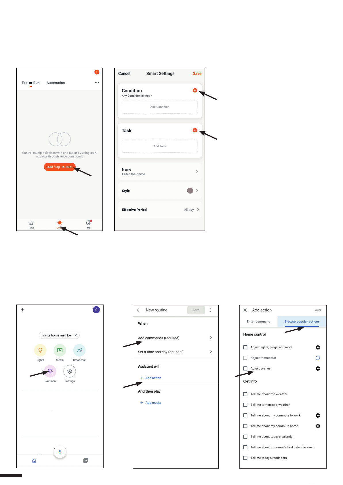
6.3 - USING VOICE CONTROLS
In order to set up voice commands, you must create a scene on OneSmart and then associate it with a Google or Alexa
routine by choosing the phrase to pronounce to match the most appropriate action.
Speech controls for automation control depend on the operation of START contact at the automation plant.
6.3a - CREATING A SCENARIO ON ONE SMART
6.3b - CREATING A GOOGLE ROUTINE
1 - On the Google Home application, select Routines (1)
2 - Create a new routine and insert the phrase you want to pronounce to “Add Commands” (2)
3 - On “+ Add Action” (3), select “Browse popular actions” (4) and then “Adjust Scenes” (5)
4 - Select the scene created on One Smart in procedure 6.3a.
(1)
(2)
(3)
- On the OneSmart application go
to the Smart window (1)
- Press “Add Tap to Run” (2)
- As a condition, select “Click to
execute” (3)
- Select the device, then select the
“Start” command (4)
- Rename and save
(4)
(1)
(2)
(3)
(5))
(4)
14

6.3c - CREATING A ALEXA ROUTINE
1 - On Alexa application, select the menu (1)
2 - Select “Routinese” (2), and then add a new one
3 - Enter the name (3), the phrase you want to pronounce (4), and “add an action” (5) select “Smart Home”, then select
“Control scene”. Select the scene created on One Smart in procedure 6.3a.
6.3c - DETAILED
The operation of the Start and therefore voice commands also depend on the operation of START contact in the
automation control unit.
It is recommended to create voice commands consistent with the operation of the installation.
Voice command tips based on how the start works
START SET AS STEP-STEP (when it’s close, open / when it’s open, close / during the moving stops)
If automation is controlled without being visible, a generic command such as “start cacello/garage”, “gate/garage” must be
created
If you control automation by seeing its status, you can create multiple voice commands: “open the gate/garage”, “lock the
gate/garage” or “close the gate/garage”.
All of these commands refer to the same action (closing the start contact).
Clearly if the gate is in motion and the “open gate” command is sent, it will stop.
START SET AS OPEN ONLY, CONDOMINAL FUNCTION (whatever automation status the start will open)
Suggested commands “Open Gate” or “Open Garage”
(1)
(2)
(4)
(3)
(5)
15

7 - ADVANCED PROGRAMS
7.1 VIEWING THE DOOR STATUS ON THE APP
To display the status of the door (open, closed, partially open) on the app, you must connect the contacts to the control
unit.
The control unit can work with:
- two normally closed contacts with no voltage
typically this means there are two micro limit switches, one for when the door opens and one for when it closes,
connected to the relevant inputs (terminals 6, 7 and 8). When the door touches the microswitch, the contact must open;
this turns on the green light in the app.
- two normally open contacts with no voltage
typically this means there are two micro limit switches, one for when the door opens and one for when it closes,
connected to the relevant inputs (terminals 6, 7 and 8). When the door touches the microswitch, the contact must close;
this turns on the green light in the app.
- one normally closed contact with no voltage when opening
typically this means there is one micro limit switch for when the door opens, connected to the relevant input (terminal 6,
7). When the door touches the microswitch, the contact must open; this turns on the green light in the app and turns off
the other light.
- one normally open contact with no voltage when opening
typically this means there is one micro limit switch for when the door opens or closes, connected to the relevant input
(terminal 6, 7). When the door touches the microswitch, the contact must close; this turns on the green light in the app
and turns off the other light.
- one normally open contact with 12-24 VDC
typically this means there is a status light (12 or 24 VDC) for the connected door, connected to the relevant input (terminal
6, 7). When the status light is on, the green light also comes on in the app and the other light goes off, and vice versa.
16

8. Closing NO contact
NOTE: to use this configuration you
must follow the procedure on the next page
NOTE: to use this configuration you
must follow the procedure on the next page
NOTE: to use this configuration you
must follow the procedure on the next page
NOTE: to use this configuration you
must follow the procedure on the next page
6. Opening NO contact
7. Common
7. Opening NO contact
8. Contact
12/24 VDC
8. Common
7. Common
7. Opening NC contact
8. Common
8. Closing NC contact
6. Opening NC contact
7. Common
OPERATOR CONTROL UNIT
GATE
WARNING LIGHT OUTPUT FOR GATE WARNING LIGHT 12/24 VDC
operation must be
warning light on = gate open
warning light off = gate closed
TWO NORMALLY CLOSED CONTACTS WITH NO VOLTAGE TWO NORMALLY OPEN CONTACTS WITH NO VOLTAGE
ONE NORMALLY CLOSED CONTACT WITH
NO VOLTAGE WHEN OPENING
ONE NORMALLY OPEN CONTACT WITH
NO VOLTAGE WHEN OPENING
ONE CONTACT WITH 12-24 VDC (WARNING LIGHT)
17

SETTING THE CONTACT FOR LIMIT SWITCHES
Default: 2 NO contacts
This procedure is used to set the type of contacts of limit switches.
PROCEDURE
STEP 1
With a paper clip makes a long press of the “hidden” button.
The LED turns on light blue/pink cyclically.
Release the key when the led is light blue.
STEP 2
Press the button 1 on the receiver for a short time and count the number of Flashes emitted by the LED:
FLASHES
NUMBER
FUNCTION
1 No limit switches
2 n°2 NC contacts
3 n°2 NO contacts (default)
4 n°1 NC contact
5 n°1 NO contact
6 n°1 contact 12/24Vdc
STEP 3
Press the button for a short time during the Flash that corresponds to the
function desired to end the count.
The led turns off
ACTION: Short press of button 1
LED: Count the number of Flashes
ACTION: Short press of button 1
LED: Turns off
18

USE THE LIMIT SWITCHES TO CREATE AN AUTOMATION
From the “Smart” screen, you can create automation, that is, automatic events.
You can enter conditions in the automation setup menu:
- door closed
- closing action
- open door
- opening action
Automation Examples:
- when the gate starts to open the garden lights on
- when the gate is open, notify me
7.2 GRAPHICS OF THE APPLICATION INTERFACE
You can change the interface according to the type of automation you are going to control.
The appearance does not affect the functionality of the control unit.
There are 4 types of screens:
garage (1), swing gate (2), sliding gate (3) and generic atuomation (4).
GARAGE INTERFACE
closed automation
(if limit switches are
present)
open automation
(if limit switches are
present)
19

SWING GATES INTERFACE
SLIDING GATES INTERFACE
GENERIC INTERFACE
closed automation
(if limit switches are present)
closed automation
(if limit switches are present)
closed automation
(if limit switches are present)
open automation
(if limit switches are present)
open automation
(if limit switches are present)
open automation
(if limit switches are present)
20
Table of contents
Other Nexta Tech Gate Opener manuals

Popular Gate Opener manuals by other brands


Topens
Topens CASAR HJ4021 user manual

Centurion
Centurion LEVER4 installation manual

King gates
King gates STARG8 24 programming

International Door Closers
International Door Closers SWINGER 300 installation instructions

Genius
Genius MILORD5 manual

Telcoma
Telcoma PASSO CARD Receiver installation instructions


