Nextiva S4100 User manual

Nextiva S4100 Series Installation Guide
www.verint.com/manuals 1
© 2007-2009 Verint Systems Inc. All Rights Reserved Worldwide. March 12, 2009
This installation guide provides instructions for installing and performing
the initial configuration of the Nextiva®S4100 series wireless
encoder/transmitter and decoder/receiver in a point-to-point context. It
covers the S4100 and S4100-2V. For more information on specific
configuration, compliance to standards, and other aspects of the product,
refer to the Nextiva S4100 Series User Guide.
Installation Kit
The package contents are: Hardware Overview
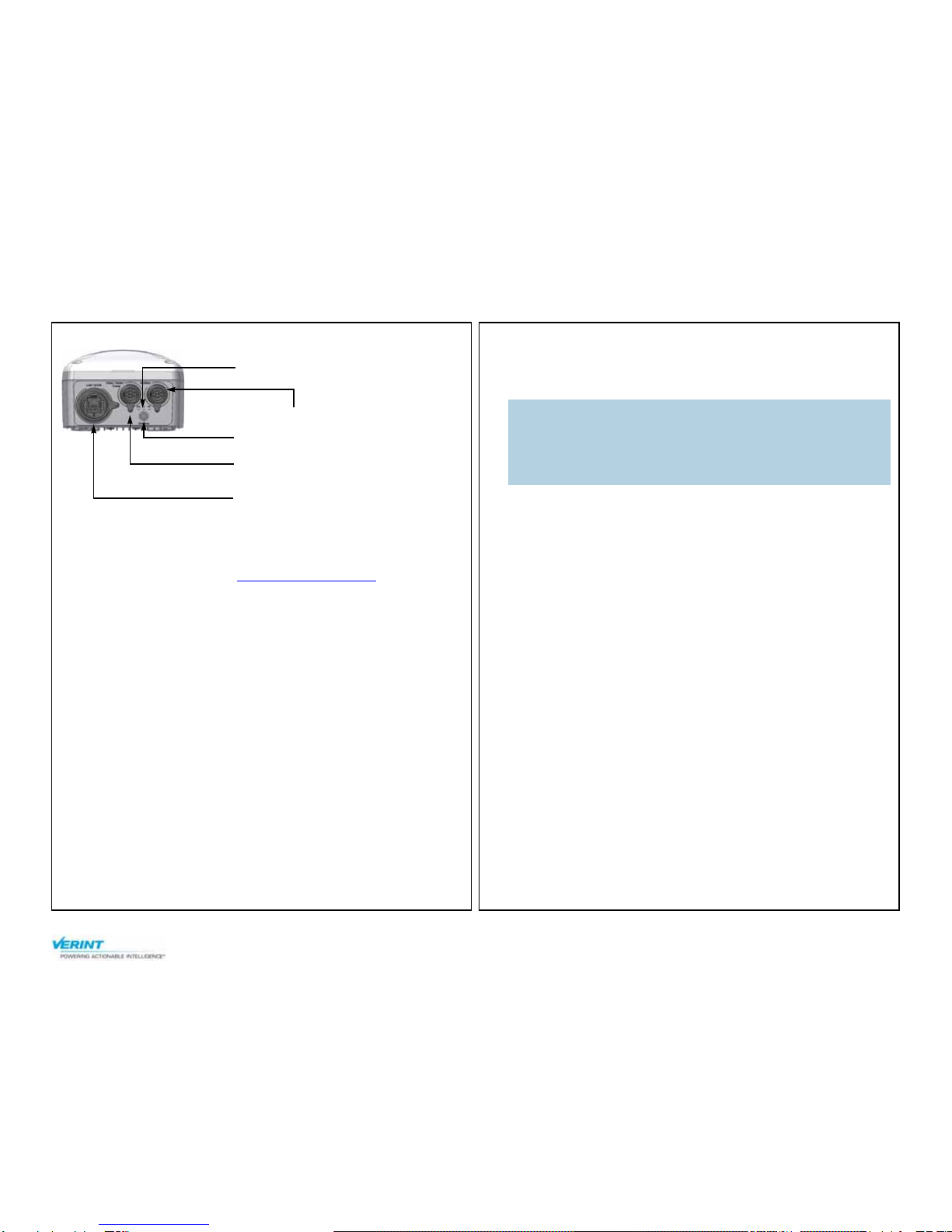
Front:
Note: The S4100 series device must be installed by certified
professionals.
Prior to deployment in the field, this wireless device requires
configuration and testing.
Item Description
Wireless system S4100 or S4100-2V, each made of a receiver
(-R) and transmitter (-T). Each device
includes an integrated antenna.
Mounting assembly set One set per device for installation on a wall
or pole
Cable for video, serial
port, and power Two cables for the S4100, four cables for the
S4100-2V
Printed material This installation guide
Options
High-gain antenna An external antenna; the available antennas
vary depending on the frequency band and
the country.
CABAA cable A cable for alarm or audio
CABET-25 cable An 82-foot (25-meter) outdoor Ethernet
cable with a weatherproof connector
CABET-50 cable A 164-foot (50-meter) outdoor Ethernet
cable with a weatherproof connector
CABPV cable A cable for video, serial port, and power
PS2440 power supply An indoor-only 24V AC power supply
Note: You must use only antennas certified by Verint. You must enter the
antenna gain in the device to ensure that the combined
transmission power of the device and antenna does not exceed the
maximum value established by your country’s regulations. For
more information, refer to the Nextiva S4100 Series User Guide.
Item Description
Integrated antenna
Nextiva S4100 Series Installation Guide
www.verint.com/manuals 2
© 2007-2009 Verint Systems Inc. All Rights Reserved Worldwide.
Back:
Point-to-Point Configuration
To configure the device, you need the SConfigurator software. It is
included on the Verint web site: www.verint.com/manuals. Copy its
executable file (SConfigurator.exe) to the hard disk of your computer.
The configuration tasks are:
1. Preparing the wireless system
2. Providing SConfigurator parameters
3. Providing the initial parameters
To prepare the wireless system:
1. Change the IP address of the computer running SConfigurator. For the
detailed procedure, refer to the Nextiva S4100 Series User Guide. The
recommended settings are:
IP address: 172.16.23.1
Subnet mask: 255.255.0.0
Default gateway: 172.16.23.1
Write down the initial values to put them back when the configuration
is finished.
2. In a lab, unpack the receiver (-R) and the transmitter (-T) and set
them on a table.
3. Write down the serial numbers of the devices in a safe place.
4. Plug the supplied video/serial/power cable into the main connector of
the S4100-R.
5. Power the S4100-R using the red and black wires of the
video/serial/power cable.
a. In 12V DC, connect each power wire of the power cable to the
corresponding wire of the power supply: the red wire to the input
(+) wire and the black wire to the ground wire (-). For more
information, refer to the power supply documentation.
b. In 24V AC, connect each power wire of the supplied cable to a wire
on the power supply. Both wires are used for power.
c. Connect the electrical plug into the outlet.
6. Connect an Ethernet cable between the network (RJ-45) connector on
the S4100-R and the computer.
7. When the boot sequence of the receiver is completed, power the
S4100-T (repeat step 5).
To provide SConfigurator parameters:
1. Start SConfigurator by double-clicking SConfigurator.exe on your
hard disk.
Auxiliary connector
Main connector for video 1, serial
port, and power
Network (RJ-45) connector
LEDs
External SMA antenna connector
Warning: To avoid material damages, you must never power any two
devices while their antennas are facing one another with a
distance of less than 10 feet (3 meters).
On an S4100-2V, do not use the red and black wires of the
second video/serial/power cable.

Nextiva S4100 Series Installation Guide
www.verint.com/manuals 3
© 2007-2009 Verint Systems Inc. All Rights Reserved Worldwide.
2. In the General tab, click Program Options.
3. In the IP Address of the PC list, select 172.16.23.1. If it does not
appear in the list, it may be because you did not temporarily change
the IP address of your computer.
4. Ensure that the VSIP Port is 5510; otherwise, click Default.
5. Ensure that the Discovery IP Address is 255.255.255.255;
otherwise, click Reset to Broadcast.
6. Click OK.
7. Select the Units tab, then click Discover.
To provide the initial parameters:
1. Select the S4100-R device, then click Configure.
2. Click Quick Setup.
3. In the Unit Name boxes, provide a meaningful name for the devices.
4. In the Country box, select the country of operation of the pair of
devices. Assign the proper country to comply to the DFS/TPC
regulations, if applicable, to respect the maximum EIRP, and to use
the proper set of frequency channels.
5. Ensure that the Repeater Mode value is Disabled.
Nextiva S4100 Series Installation Guide
www.verint.com/manuals 4
For more information, refer to the Nextiva S4100 Series User Guide, which is available on www.verint.com/manuals.
© 2007-2009 Verint Systems Inc. All Rights Reserved Worldwide. 23-500-0029-004
6. In the Passkey box, enter the wireless passkey common to the
transmitter and receiver. This user-supplied passkey is case sensitive
and must have exactly 16 characters.
7. In the Video Quality box (two boxes are available for a -2V product),
select the desired video quality. For the definition of the six available
presets, refer to the Nextiva S4100 Series User Guide.
8. Click Save. The S4100-T receives its configuration through the
wireless network. The devices reboot.
9. In the Unit Wireless Configuration window, click Close.
10. In the SConfigurator window, click Exit.
11. Unplug the Ethernet cable from the S4100-R device, then put back the
dust cap on the network (RJ-45) connector.
12. Connect the monitor and camera to the devices; ensure that RF and
video communication works properly in your wireless system.
13. Change the IP address of the computer back to its original value.
Installation
1. Fix the mounting assembly on the device, then install the device in its
final location. For instructions, refer to the Nextiva S4X00 Mounting
Assembly Installation Guide included with the mounting assembly set.
2. Remove the dust caps from the main (Video/Serial/Power) and
optionally the auxiliary connectors.
3. Plug the video/serial/power cable on the main connector of the S4100
device. To properly install the cable connector on the device, use your
hands and turn until it blocks. Do not use pliers.
4. Plug the BNC video connector of the video/serial/power cable on the
target equipment associated to video 1.
5. Perform the serial connection to the target equipment.
6. If your device is a -2V model:
a. Connect the second video/serial/power cable to the Auxiliary
connector of the S4100 device.
b. Plug the BNC video connector of the second video/serial/power
cable on the target equipment associated to video 2.
c. Perform the serial connection to the target equipment.
7. If you purchased the alarm/audio option, plug the supplied
alarm/audio cable into the Auxiliary connector of the device.
For more information about surge protection, refer to the “Surge
Protection” appendix in the Nextiva S4100 Series User Guide.
8. To properly fuse the power supplied to the wireless device, install a
fuse between the power source and the power cable. The fuse must
have the following ratings: UL Listed, 250V, 2.5A, Fast-Acting.
9. Power up the S4100 device.
10. Repeat step 1 to step 9 for the second device.
Note: You must install the mounting assembly on the S4100. It is
required to properly mount and securely ground the wireless
device.
Tip: For easy maintenance, it is strongly recommended to plug an
outdoor Ethernet cable on the device and to run it down the pole.
Tie the cable to the pole 2 feet (0.7 meter) or less below the device,
while ensuring that there is no tension between the device and the
tie point. Insert the other end of the cable in a waterproof electrical
box for outdoor applications. Add external surge protection near the
device to protect the Ethernet port.
Tip: If you are installing the S4100 equipment in a lightning prone
environment or in a site where large AC mains power fluctuations
are a common occurrence, add external surge protection to secure
your equipment.
Tip: If the S4100 is directly exposed to the sun in an environment likely
to reach 122°F (50°C), install a sun shield. Otherwise, reduce the
maximum operating temperature by 18°F (10°C) to protect the
equipment; that is, without a sun shield, the maximum temperature
should be 104°F (40°C).
This manual suits for next models
1
Table of contents
Other Nextiva Receiver manuals


