manuals.online logo
Brands
  1. Home
  2. •
  3. Brands
  4. •
  5. NEXTIVITY
  6. •
  7. Network Hardware
  8. •
  9. NEXTIVITY CEL-FI CONNECT C41 User manual

NEXTIVITY CEL-FI CONNECT C41 User manual

CEL-FI®CONNECT C41
Quick Start Guide
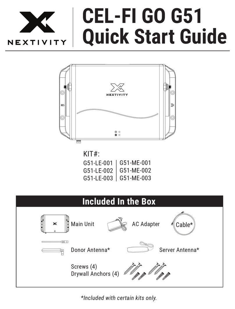
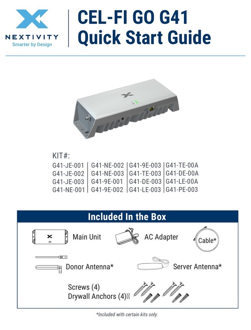
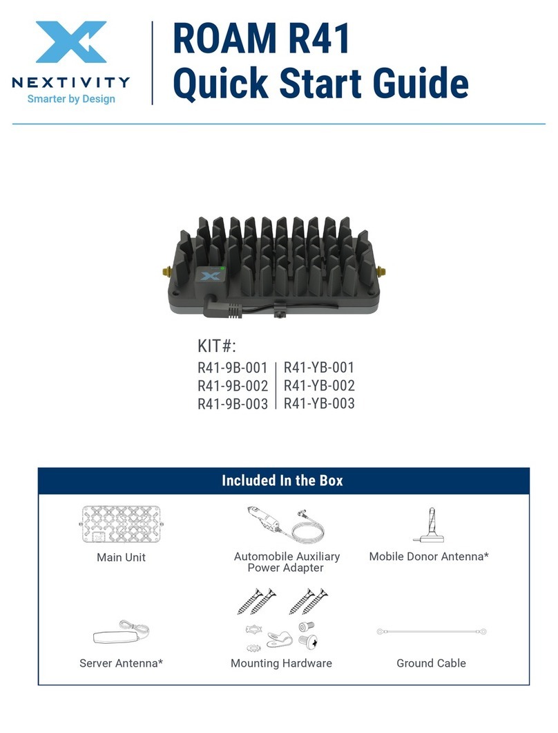
Included In the Box
C41-9B-00C
C41-JB-00C
C41-KB-00C
KIT#:
C41-9B-003
C41-JB-003
Mounting Screws (4)
Drywall Anchors (4)
Donor Antenna*Main Unit
* Included with certain kits only
AC Adapter
Quick Installation IMPORTANT: Your CEL-FI CONNECT C41 is an electronic device. It must
be kept indoors and in a dry, cool, well-ventilated area.
11
3344
22
Select Donor Antenna Location
Attach Cables Plug In the Main Unit
Select Main Unit Location
Use your phone to nd the window with the best cellular
signal. Install the Donor Antenna on this window by removing
the four adhesive covers and sticking them to the glass.
Attach the cable from the Donor Antenna to the Donor Port
on Main Unit.
Attach the short cable coming out of the Main Unit to the
Server Port on the base of the unit
Plug in the Main Unit to power with the included AC adapter.
Attach the power cable clamp to manage the AC adapter
cable.The LED on the front will blink during set up and turn
green when the device is ready.
Selecting the ideal location for the Main Unit is important
to ensure your system provides reliable coverage. The
Main Unit should be isolated from the Donor Antenna,
with greater separation providing best performance. Make
sure the Nextivity logo on the Main Unit faces where
coverage is needed and away from the Donor Antenna.
Donor
Antenna
Donor
Antenna
Donor
Antenna
Main Unit
Donor Antenna
Main Unit
LED
(backside)
(frontside)
(DC)
(Clamp)
Donor
Antenna
Main Unit
Velcro Tape (4)
for Window
55Congure with the WAVE App
The WAVE App can be used to review your
installed system’s performance, including viewing
real-time signal strength.
Scan to Download:
The WAVE App is available
for smartphones and
tablets.
Velcro Tape (4)
for Window
1
2 3
4
REQUIRED HARDWARE
NOTE: This package comes equipped with Mounting Screws and Drywall Anchors for mounting to the ceiling.
Before installing, ensure there are no wires, other objects, or metal plates above the drywall that may interfere
with the inserts, screws, or mounted units.
Mark the 4x mounting hole
locations to drill.
In each marked spot, use a
3/16” drill bit to drill guide
holes for mounting screws.
Install the Drywall Anchors and Mounting Screws
with the Main Unit. Continue with Step 3 of Quick
Installation instructions.
Make sure the Donor Antenna cable (16.4 ft/5 m)
and AC Adapter cable (6 ft/1.85 m) both can reach
the respective ports on the Main Unit at the ceiling
mounting location selected.(Refer to the Quick
Installation section)
Mounting Screws (4)
Ceiling Mount Option
AC Adapter
Main Unit Donor Antenna
Ceiling Mounting Instructions (Optional)
Copyright © 2023 by Nextivity, Inc., U.S. Patents pending. All rights reserved. The Nextivity and CEL-FI logos are registered trademarks of Nextivity,
Inc. All other trademarks or registered trademarks listed belong to their respective owners. Designed by Nextivity, Inc. in California.
qsg-connect-c41_eng_23-0801
M/N Bands
Supported Link
Output
Power
(dBm)
C41-9B
1, 3, 7 Uplink 22
Downlink 10
8, 20 Uplink 20
Downlink 10
C41-JB
1, 3, 7, 40 Uplink 22
Downlink 10
5, 8, 28L Uplink 20
Downlink 10
C41-KB
3Uplink 22
Downlink 10
8, 20 Uplink 20
Downlink 10

Other NEXTIVITY Network Hardware manuals

NEXTIVITY CEL-FI GO G41 User manual

NEXTIVITY

NEXTIVITY CEL-FI GO G41 User manual

NEXTIVITY ROAM R41 User manual

NEXTIVITY

NEXTIVITY ROAM R41 User manual

NEXTIVITY SHIELD MegaFi User manual

NEXTIVITY

NEXTIVITY SHIELD MegaFi User manual

NEXTIVITY CEL-FI GO G51 User manual

NEXTIVITY

NEXTIVITY CEL-FI GO G51 User manual

NEXTIVITY SHIELD MegaFi User manual

NEXTIVITY

NEXTIVITY SHIELD MegaFi User manual

Popular Network Hardware manuals by other brands

AMP DMT10768T097-31WT user guide

AMP

AMP DMT10768T097-31WT user guide

oventrop Datalog CS-BS-1 Installation and operating instructions for the specialised installer

oventrop

oventrop Datalog CS-BS-1 Installation and operating instructions for the specialised installer

ATTO Technology iPBridge 2700C Specifications

ATTO Technology

ATTO Technology iPBridge 2700C Specifications

Bosch D9210C Program entry guide

Bosch

Bosch D9210C Program entry guide

Zhone MALC-XP Specification sheet

Zhone

Zhone MALC-XP Specification sheet

Lanner HTCA-6400 user manual

Lanner

Lanner HTCA-6400 user manual

Dongguan Sunhans Technology SHPRO24G10WANT Quick installation guide

Dongguan Sunhans Technology

Dongguan Sunhans Technology SHPRO24G10WANT Quick installation guide

Beck com.tom INDUSTRY 100.WLAN.W Startup guide

Beck

Beck com.tom INDUSTRY 100.WLAN.W Startup guide

D-Link DNR-2020-04P Quick installation guide

D-Link

D-Link DNR-2020-04P Quick installation guide

Alacritech SEN1811XT Hardware installation guide

Alacritech

Alacritech SEN1811XT Hardware installation guide

Lorex LNR110 Series instruction manual

Lorex

Lorex LNR110 Series instruction manual

Internet Security Systems Proventia A604 user guide

Internet Security Systems

Internet Security Systems Proventia A604 user guide

QNAP TS 53 DU Series manual

QNAP

QNAP TS 53 DU Series manual

HP A3550A - High Availability Disk Arrays Model 20 Storage... installation guide

HP

HP A3550A - High Availability Disk Arrays Model 20 Storage... installation guide

MikroTik CRS310-1G-5S-4S Plus OUT quick guide

MikroTik

MikroTik CRS310-1G-5S-4S Plus OUT quick guide

Smawave Technology MGL6201A user manual

Smawave Technology

Smawave Technology MGL6201A user manual

Neoway N715-EA Hardware user's guide

Neoway

Neoway N715-EA Hardware user's guide

DT Research MA1352GL Basic operation guide

DT Research

DT Research MA1352GL Basic operation guide

manuals.online logo
manuals.online logoBrands
  • About & Mission
  • Contact us
  • Privacy Policy
  • Terms and Conditions

Copyright 2025 Manuals.Online. All Rights Reserved.