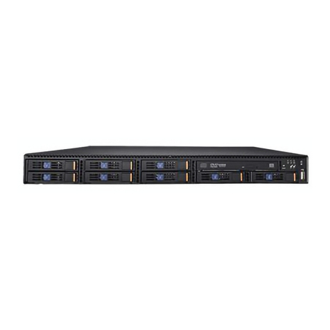
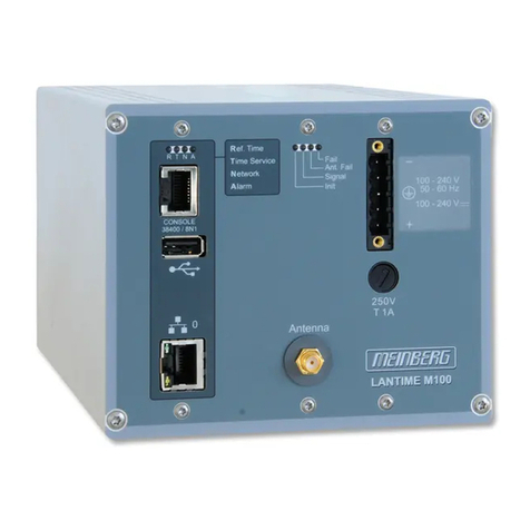
NGT Communication Server User manual

International Pager Services B.V. | II_DP_Server_En_2311
►Communication Server
►DP6000-IP Interface
►Software and Licenses
►Options
►Application notes
►Maintenance information
Powered by:
Next Generation
Technology
Communication Server
Installation Instructions
II_DP_Server_En_2311

Communication Server | Installation Instructions en | 2
International Pager Services B.V. | II_DP-Server_En_2311
Table of contents
1.1 Function.............................................................................................................................................................8
1.2 Digital version....................................................................................................................................................8
1.3 Precautions and notes.......................................................................................................................................8
1.3.1 Signs .................................................................................................................................................................8
1.4 Examples...........................................................................................................................................................8
1.5 Disclaimer..........................................................................................................................................................8
1.5.1 Illustrations ........................................................................................................................................................8
2Installation checklist.............................................................................................................................................9
3Introduction..........................................................................................................................................................10
3.1 Basic Functions.................................................................................................................................................10
3.2 Basic System set-up..........................................................................................................................................10
3.2.1 Other Highlights................................................................................................................................................10
4Commercial Items................................................................................................................................................11
4.1 Special Packages..............................................................................................................................................11
4.2 Ordering ............................................................................................................................................................11
4.2.1 To be organized locally......................................................................................................................................11
4.3 Functional Description.......................................................................................................................................12
4.3.1 Communication Server; LBB8000/00 ................................................................................................................12
4.3.2 Image Basic software Package; LBB LBB8000/01............................................................................................12
4.3.3 DP6000-IP interface; LBB8001/00.....................................................................................................................12
4.3.4 Input contact module; LBB5901/00....................................................................................................................12
4.3.5 Output contact module; LBB5902/00.................................................................................................................12
4.3.6 ESPA 4.4.4. interface module; LBB5903/00......................................................................................................12
4.3.7 RS485 Interface module LBB5904/00...............................................................................................................13
4.3.8 Cable set (set of 2); LBB 8003/00......................................................................................................................13
4.4 Licenses............................................................................................................................................................13
4.4.1 Activation Logging; LBB 8600/00.......................................................................................................................13
4.4.2 Activation Personal Security; LBB 8601/00 .......................................................................................................13
4.4.3 Activation Multi Users; LBB 8602/00 .................................................................................................................13
4.4.4 Activation Multi Site; LBB 8603/00.....................................................................................................................13
4.4.5 Activation ESPA; LBB 8604/00..........................................................................................................................13
4.4.6 Activation I/O contacts; LBB 8605/00................................................................................................................14
4.4.7 Activation 3rd Party Connection; LBB8608/00....................................................................................................14
4.4.8 Maintenance agreement; LBB 8609/00.............................................................................................................14
4.4.9 Remote Support Device ....................................................................................................................................14
4.4.10 Subscription Fee................................................................................................................................................14
4.4.11 Ordering additional licenses afterwards.............................................................................................................14
4.5 Server Packages explained...............................................................................................................................14
4.5.1 Basic Messaging Server....................................................................................................................................14
4.5.2 Basic Personal Security Server.........................................................................................................................14
4.5.3 Extended Communication server.......................................................................................................................14
5The IP Network....................................................................................................................................................15
5.1 Minimum IP network requirements....................................................................................................................15
5.1.1 Communication Server......................................................................................................................................15
5.1.2 Specification Communication server PC ...........................................................................................................15
5.2 DP6000-IP Interface..........................................................................................................................................15
5.3 Web browser and settings.................................................................................................................................15
5.3.1 Automatic Windows Updates.............................................................................................................................16
5.3.2 Auto fill in...........................................................................................................................................................16
5.3.3 Audio settings....................................................................................................................................................16
5.4 Reserved IP addresses.....................................................................................................................................16
5.4.1 Port settings ......................................................................................................................................................16
5.5 IP-Network topology..........................................................................................................................................17
5.5.1 Virtual IT structure.............................................................................................................................................17
5.5.2 Management gateway (IP address)...................................................................................................................17
5.5.3 Enable Ping Replies..........................................................................................................................................18
5.6 Network settings................................................................................................................................................18
5.6.1 Network 0 settings.............................................................................................................................................18
5.6.2 Network 1 settings.............................................................................................................................................19
5.7 Network test-tools (build in)...............................................................................................................................19
5.7.1 Ifconfig...............................................................................................................................................................19
5.7.2 Ping...................................................................................................................................................................19

Communication Server | Installation Instructions en | 3
International Pager Services B.V. | II_DP-Server_En_2311
5.7.3 Traceroute.........................................................................................................................................................19
5.8 Alternative Network test-tools............................................................................................................................20
6Getting started .....................................................................................................................................................21
6.1 Preparations......................................................................................................................................................21
6.2 Interconnections and operation .........................................................................................................................21
6.2.1 Loudspeaker on client PC .................................................................................................................................21
6.2.2 Audio settings in Web browser..........................................................................................................................21
6.3 IP interfaces ......................................................................................................................................................21
6.4 Switching On the Communication Server..........................................................................................................21
7DP6000-IP Interface Hardware............................................................................................................................22
7.1 Introduction........................................................................................................................................................22
7.2 Hardware- and user interfaces ..........................................................................................................................22
7.2.1 Paging bus interface..........................................................................................................................................22
7.3 Power Supply ....................................................................................................................................................23
7.4 Pushbuttons ......................................................................................................................................................23
7.5 Display information............................................................................................................................................23
7.6 Menu .................................................................................................................................................................23
7.7 MAC address.....................................................................................................................................................23
7.8 Diagnose menu .................................................................................................................................................23
7.9 Setup menu.......................................................................................................................................................23
7.9.1 IP settings..........................................................................................................................................................23
7.9.2 Set the IP address.............................................................................................................................................24
7.9.3 Set the Gateway................................................................................................................................................24
7.9.4 Set the subnet mask..........................................................................................................................................24
7.9.5 Set the Port address..........................................................................................................................................24
7.9.6 Set IP settings to default....................................................................................................................................25
7.10 Testfunctions menu...........................................................................................................................................25
7.11 Software versions menu....................................................................................................................................25
7.12 Dimensions........................................................................................................................................................25
7.12.1 Mechanical ........................................................................................................................................................25
7.12.2 Drilling pattern ...................................................................................................................................................25
7.13 Install the ESPA interface module.....................................................................................................................26
7.13.1 The RS232 cable...............................................................................................................................................26
7.14 Prepare the LBB5843/01 MPC heads ...............................................................................................................26
7.14.1 Set the address of the MPC ..............................................................................................................................26
7.14.2 Install the RS485 module ..................................................................................................................................26
7.14.3 RS485 Cable.....................................................................................................................................................26
7.14.4 Configure the RS485 interface module..............................................................................................................27
7.14.5 Monitoring RS485 connection ...........................................................................................................................27
7.15 Installing Internal I/O contact modules...............................................................................................................27
7.15.1 Internal Output contact modules........................................................................................................................27
7.15.2 Internal Input contact module ............................................................................................................................28
7.15.3 Cable set...........................................................................................................................................................28
7.15.4 Resistor network................................................................................................................................................28
7.15.5 Set address of the input contact module ...........................................................................................................29
7.16 LED indications..................................................................................................................................................29
7.16.1 LED indications; IP interface module.................................................................................................................29
7.16.2 LED indications; Input Contact module..............................................................................................................29
7.16.3 LED indications; Output contact module............................................................................................................29
7.16.4 LED indications; ESPA module .........................................................................................................................30
7.16.5 LED indications; RS485 module........................................................................................................................30
7.16.6 LED indications DP6000-IP Interface................................................................................................................30
7.17 Firmware version...............................................................................................................................................31
7.18 Replace a DP6000-IP Interface.........................................................................................................................31
7.18.1 License Check...................................................................................................................................................31
7.18.2 Replacement options.........................................................................................................................................31
7.18.3 Exchange the TCP-IP module...........................................................................................................................32
7.18.4 Apply for new licenses.......................................................................................................................................32
7.18.5 Replace a defect DP6000-IP Interface..............................................................................................................32
7.18.6 Repair Costs......................................................................................................................................................32
8Programming.......................................................................................................................................................33
8.1 Set up a Client IP-connection............................................................................................................................33
8.2 The start screen.................................................................................................................................................33
8.3 Set header colour..............................................................................................................................................33
8.4 Set Language....................................................................................................................................................33

Communication Server | Installation Instructions en | 4
International Pager Services B.V. | II_DP-Server_En_2311
8.4.1 Server language................................................................................................................................................33
8.4.2 User language...................................................................................................................................................33
8.5 Log in.................................................................................................................................................................34
8.6 Main screen.......................................................................................................................................................34
8.6.1 Maximum logged on users ................................................................................................................................34
8.6.2 Auto Log of........................................................................................................................................................34
8.7 Log out ..............................................................................................................................................................34
9System Licenses..................................................................................................................................................35
9.1.1 Update the License file......................................................................................................................................35
9.1.2 Check present Licenses....................................................................................................................................35
10 Working mode......................................................................................................................................................36
10.1 Manned operation mode....................................................................................................................................36
10.2 Unmanned operation mode...............................................................................................................................36
10.3 Remote Reset....................................................................................................................................................36
11 System Configuration...........................................................................................................................................37
11.1 Define a building................................................................................................................................................37
11.1.1 Add a site/building.............................................................................................................................................37
11.1.2 Add a drawing to the building............................................................................................................................37
11.2 Location detection .............................................................................................................................................38
11.2.1 Location monitoring option ................................................................................................................................38
11.3 Overview programmed locations.......................................................................................................................38
11.3.1 Sorted overview of location beacons.................................................................................................................38
11.3.2 View programmed Location beacons ................................................................................................................38
11.3.3 Edit programmed Location beacons..................................................................................................................38
11.3.4 Guidelines to program Location data.................................................................................................................38
11.3.5 Add Location Beacon(s)....................................................................................................................................39
11.3.6 Export location data...........................................................................................................................................39
11.3.7 Delete location beacon(s)..................................................................................................................................40
11.3.8 Representation of location graphics ..................................................................................................................40
11.3.9 Drawing quality:.................................................................................................................................................41
11.3.10 Location monitoring option ................................................................................................................................41
11.3.11 Guard tour option...............................................................................................................................................41
11.4 Define peripherals .............................................................................................................................................42
11.4.1 Add a Peripheral................................................................................................................................................42
11.4.2 To view peripheral settings................................................................................................................................42
11.4.3 Configure Transmitter DP6000 TX ....................................................................................................................42
11.4.4 Configure DP6000 RX.......................................................................................................................................43
11.4.5 Configure a DP6000-IP Interface.......................................................................................................................43
11.5 Monitoring the DP6000-IP Interface ..................................................................................................................45
11.5.1 Line occupation error.........................................................................................................................................45
11.5.2 Lost IP connection.............................................................................................................................................45
11.5.3 Sent an automatic message when IP connection is lost....................................................................................45
11.6 Configure a Communication Server...................................................................................................................46
11.6.1 Configure the main server.................................................................................................................................46
11.6.2 Database errors from Server.............................................................................................................................46
11.6.3 IP connection lost from Server ..........................................................................................................................46
11.7 Notifications.......................................................................................................................................................47
11.8 Assign mobiles to the system............................................................................................................................48
11.9 Add an individual mobile....................................................................................................................................48
11.9.1 Absent handling * ..............................................................................................................................................48
11.9.2 Indoor location detection *.................................................................................................................................49
11.9.3 Switched off * ....................................................................................................................................................49
11.9.4 Out Rack test * ..................................................................................................................................................49
11.9.5 Low battery Indication *.....................................................................................................................................49
11.9.6 Automatic Scanning *........................................................................................................................................50
11.9.7 Sign of life (manual reply from mobile) *............................................................................................................50
11.9.8 Sign of life (periodical call from PS-Micro mobile) *...........................................................................................50
11.9.9 Link mobile to a Building/site *...........................................................................................................................51
11.10 Link a mobile to Peripherals (DP6000-IP Interfaces) * ......................................................................................51
11.10.1 Link mobile to Main Peripheral(s) *....................................................................................................................51
11.10.2 Link mobile to Back-up Peripheral *...................................................................................................................51
11.10.3 Scan Peripheral *...............................................................................................................................................51
11.10.4 Import multiple mobiles *...................................................................................................................................52
11.10.5 Export mobile data.............................................................................................................................................52
11.10.6 Delete mobiles/devices......................................................................................................................................52

Communication Server | Installation Instructions en | 5
International Pager Services B.V. | II_DP-Server_En_2311
11.11 Device screen content (Mobiles) .......................................................................................................................53
11.11.1 Visible data of a device/mobile..........................................................................................................................53
11.11.2 Sorted status overview......................................................................................................................................53
11.11.3 Operation via the status indicator......................................................................................................................53
11.11.4 Programmable info in the status indicator .........................................................................................................53
11.11.5 Set Scanning ON or Off.....................................................................................................................................54
11.12 Status screen content........................................................................................................................................55
11.13 Groups of devices (serial call) ...........................................................................................................................56
11.13.1 Create a Group of pagers (serial call)................................................................................................................56
11.13.2 Create a Group Call (Group address)................................................................................................................56
12 Alarm handling settings........................................................................................................................................57
12.1 Alarm definitions................................................................................................................................................57
12.1.1 Default technical alarm......................................................................................................................................57
12.1.2 Default PS alarm ...............................................................................................................................................57
12.1.3 Default Other alarm...........................................................................................................................................57
12.1.4 Specified alarm..................................................................................................................................................57
12.2 Alarm classes....................................................................................................................................................58
12.2.1 Alarm types .......................................................................................................................................................58
12.2.2 Edit an alarm type..............................................................................................................................................58
12.2.3 Alarm sources....................................................................................................................................................59
12.2.4 Number of visible alarm lines ............................................................................................................................59
12.3 Define Default alarms........................................................................................................................................60
12.3.1 System settings for alarm handling....................................................................................................................61
12.4 Define Specified Alarms....................................................................................................................................62
12.4.1 Create a specified alarm....................................................................................................................................62
12.4.2 Other (system) settings for alarm handling........................................................................................................64
12.5 Test the alarm function......................................................................................................................................65
12.5.1 Fault finding.......................................................................................................................................................65
12.5.2 Alarm screen layout...........................................................................................................................................65
12.5.3 The alarm sound................................................................................................................................................65
12.5.4 General System settings for alarm handling......................................................................................................65
12.5.5 View Alarm History............................................................................................................................................65
13 Create users and roles.........................................................................................................................................66
13.1 Role of users.....................................................................................................................................................66
13.1.1 Examples of roles and permissions...................................................................................................................66
13.1.2 Create roles.......................................................................................................................................................67
13.2 Add a user.........................................................................................................................................................68
13.2.1 Set user authorizations......................................................................................................................................68
13.3 Forgotten password...........................................................................................................................................69
13.3.1 System settings and alarm handling..................................................................................................................69
14 System settings....................................................................................................................................................70
14.1 Quick search .....................................................................................................................................................70
14.2 Download the system settings...........................................................................................................................70
14.3 Overview System settings .................................................................................................................................70
14.4 General system settings....................................................................................................................................72
14.5 System settings related to automatic scanning .................................................................................................72
14.6 System settings related to Alarm handling ........................................................................................................73
15 Logging of calls....................................................................................................................................................76
15.1 Logging screen..................................................................................................................................................76
15.2 Real-time call handling......................................................................................................................................76
15.3 Alarm history .....................................................................................................................................................77
15.3.1 To access ‘own alarm history’ ...........................................................................................................................77
15.3.2 To access ‘full alarm history’ .............................................................................................................................77
16 Archives...............................................................................................................................................................78
16.1 Accessibility of Archives....................................................................................................................................78
16.2 Obtain Alarm reports .........................................................................................................................................78
16.2.1 Download alarm history data.............................................................................................................................79
16.3 Outgoing calls....................................................................................................................................................80
16.3.1 Meaning of the data (Fields) that can be exported; Outgoing calls....................................................................80
16.4 Technical Logging .............................................................................................................................................81
16.4.1 Meaning of the data that can be exported; Technical logging ...........................................................................82
16.5 Guard tours archive...........................................................................................................................................82
16.6 Convert CSV file to Excel file.............................................................................................................................83
17 Application notes..................................................................................................................................................84
17.1 Out Of Range (OOR) call ..................................................................................................................................84

Communication Server | Installation Instructions en | 6
International Pager Services B.V. | II_DP-Server_En_2311
17.2 Special Calls......................................................................................................................................................84
17.2.1 Edit a Special call..............................................................................................................................................84
17.2.2 Detection of call parameters..............................................................................................................................84
17.2.3 Action for Special calls ......................................................................................................................................85
17.3 Pre-defined numeric code .................................................................................................................................86
17.4 Pre-defined Messages.......................................................................................................................................86
17.5 Manual Call Button/Speed Dial Buttons.............................................................................................................86
17.5.1 Manual Call Options..........................................................................................................................................86
17.5.2 Change the color for the ‘Manual call’ button ....................................................................................................86
17.5.3 Sent Manual calls with a fixed bleep code.........................................................................................................86
17.5.4 Split long messages to 24 char/call...................................................................................................................87
17.6 Speed dial buttons/Fast dial buttons..................................................................................................................87
17.6.1 Editable Content for Speed Dial Calls ...............................................................................................................88
17.7 Predefined IP-DP6000 calls ..............................................................................................................................88
17.7.1 Program a predefined IP-DP6000 call...............................................................................................................88
17.7.2 Add a new Predefined IP-DP6000 call ..............................................................................................................89
18 Program I/O contacts...........................................................................................................................................90
18.1 Programming Output contacts...........................................................................................................................90
18.2 Layout status indicator for output contacts........................................................................................................91
18.2.1 Change the status of the output contact manually.............................................................................................91
18.3 Programming Input Contacts.............................................................................................................................92
18.3.1 Configure a Guarded internal input contact.......................................................................................................95
18.3.2 Edit a contact.....................................................................................................................................................95
18.3.3 Layout status indicator for Input contacts..........................................................................................................95
18.4 ESPA Ports .......................................................................................................................................................96
18.5 ESPA configuration ...........................................................................................................................................96
18.5.1 Program an ESPA input port .............................................................................................................................96
18.5.2 Message options; Fixed digits ...........................................................................................................................97
18.5.3 ESPA Port monitoring........................................................................................................................................97
18.5.4 Program an ESPA-out port................................................................................................................................98
18.6 Programming Mobiles........................................................................................................................................99
18.7 Preparation........................................................................................................................................................99
18.7.1 Reserved addresses..........................................................................................................................................99
18.7.2 Programmable items .........................................................................................................................................99
18.7.3 Default settings/Factory settings........................................................................................................................99
18.7.4 Select the data to be programmed ....................................................................................................................99
18.7.5 The extended method........................................................................................................................................100
18.8 Transmitter monitoring via the Server................................................................................................................101
18.8.1 Preparation........................................................................................................................................................101
18.8.2 Error indications.................................................................................................................................................101
18.8.3 Automatic TX reset call......................................................................................................................................101
18.8.4 Settings TMM type WSP_D_40971...................................................................................................................101
18.8.5 Settings TMM type LBB5905.............................................................................................................................102
18.9 CRX monitoring via the Server..........................................................................................................................102
18.9.1 Preparation:.......................................................................................................................................................102
18.9.2 Information in the numeric code of the status call .............................................................................................103
18.9.3 Status indicator for CRX....................................................................................................................................103
18.10 Guard tours .......................................................................................................................................................104
18.10.1 Create a guard tour ...........................................................................................................................................104
18.10.2 Start a guard-tour ..............................................................................................................................................104
18.10.3 Guard tour registration.......................................................................................................................................105
18.10.4 Unsuccessful Guard tour...................................................................................................................................105
18.10.5 Guard tour alarm ...............................................................................................................................................105
18.11 Location Monitoring...........................................................................................................................................105
18.11.1 Location beacon not seen for a too long time....................................................................................................106
18.11.2 Location beacon reports code F7......................................................................................................................106
18.12 System examples..............................................................................................................................................107
18.12.1 Basic system .....................................................................................................................................................107
18.12.2 Multi-client system.............................................................................................................................................107
18.12.3 Multi-site system 1.............................................................................................................................................107
18.12.4 Multi-site system 2.............................................................................................................................................107
18.12.5 3rd party connection/BMS ..................................................................................................................................107
18.12.6 Server as Master/Slave.....................................................................................................................................107
19 Technical Alarms .................................................................................................................................................108
19.1 Technical notification.........................................................................................................................................108

Communication Server | Installation Instructions en | 7
International Pager Services B.V. | II_DP-Server_En_2311
19.2 Technical calls...................................................................................................................................................108
19.3 Status screen ....................................................................................................................................................108
20 Maintenance........................................................................................................................................................109
20.1 Introduction........................................................................................................................................................109
20.2 Firmware and software versions........................................................................................................................109
20.3 Network testing..................................................................................................................................................109
20.4 Remote Maintenance ........................................................................................................................................109
20.5 Set time and date (in the Server PC).................................................................................................................109
20.5.1 Set time and date (ESXi)...................................................................................................................................109
20.6 Server Status screen and Server backup..........................................................................................................111
20.6.1 Server status.....................................................................................................................................................111
20.6.2 Restart the Server (Software reset)...................................................................................................................111
20.6.3 Incoming calls/line monitoring ...........................................................................................................................111
20.6.4 Server logs........................................................................................................................................................112
20.7 Manage the database (Communication server).................................................................................................112
20.7.1 Back-up database..............................................................................................................................................112
20.7.2 Restore database..............................................................................................................................................113
20.7.3 Back up of DP6000-IP Interfaces. .....................................................................................................................113
20.8 Modeword explanation ......................................................................................................................................114
20.9 Update firmware DP6000-IP Interface...............................................................................................................116
20.9.1 Preparation........................................................................................................................................................116
20.9.2 Upgrade instructions..........................................................................................................................................116
21 Trouble shooting..................................................................................................................................................118
21.1 Remember in case of issues:............................................................................................................................118
21.2 Technical alarms guidelines ..............................................................................................................................118
21.2.1 Technical alarms and possible remedies...........................................................................................................118

Communication Server | Installation Instructions en | 8
International Pager Services B.V. | II_DP-Server_En_2311
About this manual
1.1 Function
These Installation Instructions gives the install engineers the necessary information to install and configure the
Communication Server and DP6000-IP interface unit to be used in a DP6000/PS6000 concept as defined for the
Philips/Bosch/Atus paging and Personal Security product range.
1.2 Digital version
The Installation manual is also available as a digital file (Adobe Portable Document File, PDF).
When the PDF refers to a location that contains more data, you can click the text to go there.
1.3 Precautions and notes
The Installation manual uses 3 levels of precaution. The precaution shows the result of not obeying the instructions.
These are the types:
1. Note A note gives more data.
2. Caution If you do not obey the caution, you can cause damage to the equipment.
3. Warning If you do not obey the warning, you can cause personal injury or severe damage to the equipment.
1.3.1 Signs
The Installation and User Instructions shows each caution, warning and danger with a sign. The sign shows the result of not
obeying the instructions.
Warning: General sign for cautions warnings and dangers.
Caution: Risk of electrical shock.
Note: The general sign for a note.
1.4 Examples
The manual contains numerous examples, for instance in the form of screen shots. Please note that the examples may differ
more or less from you situation, depending on version differences, settings, configuration details, resolution, etc.
Note: The screenshots shown in this manual may appear different on your PC, depending on windows
version, configuration, etc. etc. In some cases the steps may even be slightly different than
described. It might also be possible that there are alternative ways that are not described in this manual.
1.5 Disclaimer
International Pager Services B.V. reserves the right to change data and/or specification of any equipment or software
mentioned in this publication without prior notice. Although every effort is made to ensure that the information in this
publication is accurate and correct, International Pager Services B.V. is not responsible for damage arising from its misuse.
This publication contains proprietary information, which is protected by copyright. All rights are reserved. No part of this
document may be photocopied, reproduced or translated to another language without the prior written consent of International
Pager Services B.V.
1.5.1 Illustrations
The illustrations in this manual are indicative only and may differ depending on:
►The operating system.
►The version of the application software.
►The activated language on the PC.

Communication Server | Installation Instructions en | 9
International Pager Services B.V. | II_DP-Server_En_2311
2 Installation checklist
The checklist helps you to be sure that no steps in a basic installation procedure are forgotten.
Note that the sequence in steps are important to carry out e.g. first check steps 1 to 3 before step 4 is executed.
Configuration steps to configure a system: (if items applicable).
Step nr
Action
Remark
❑
1
•Prepare the DP6000-IP Interface
Add hardware, program IP settings
❑
2
•Select the language
For user and in System settings
❑
3
•Logon as Super administrator
To make sure you have enough rights
❑
4
•Check Licenses
Check if the correct applications are activated
❑
5
•Check/Set the Network settings (Server)
For user and in System settings
❑
6
•Create Buildings/sites
For each DP6000-IP interface one building required.
❑
7
•Configure Location data
One by one or import from an excel list.
If desired also guard tour(s) and/or location
monitoring can be configured
❑
8
•Configure DP6000-IP Interface(s)
The main unit is linked to system licences
❑
9
•Add the devices
One by one or import from an excel list
❑
10
•Create Groups
Optionally
❑
11
•Create Predefined system calls
Needed for system guarding + Internal I/O contacts
❑
12
•Program the I/O contacts
•First create output- then input- contacts.
There might be internal and/or external I/O contacts
❑
13
•Set the alarm definitions/alarm types
In ‘Alarm definitions’ create always a DEFAULT
Personal Security and a DEFAULT Technical alarm
and if desired create ‘Specified Alarms’.
Set the BAR- colour of an alarm in ‘Alarm types’.
❑
14
•Set the authorisations for the several ‘Roles’
In ‘Roles’ the authorisations are set.
❑
15
•Create Roles, users and operators
Select appropriate role per user type.
❑
16
•Define pre-programmed alpha numeric messages
Optionally
❑
17
•Define pre-programmed numeric messages
Optionally
❑
18
•Define speed dial buttons
For manual button fixed digits can be set
❑
19
•If relevant add peripherals (e.g. TX, RX etc.)
Optionally; First check the peripheral type.
If desired activate guarding.
❑
20
•Check the system settings
Settings are system wide applicable.
❑
21
•Configure the RS232 (ESPA) Interface(s)
Optionally Port 3 can be set as ESPA-out.
❑
22
•Configure the RS485 Interface(s)
Only Applicable if the LBB5843/01 is used.
❑
23
•When finished create a back-up of all settings
Logging and archives are not back-upped
In the manual and in the chapter “Application notes” examples for a numerous of solutions are explained.

Communication Server | Installation Instructions en | 10
International Pager Services B.V. | II_DP-Server_En_2311
3 Introduction
The Communication Server is the heart of the system, this is a PC with installed application software. In combination with the
DP6000-IP interface both replaces the former Alpha-desk and Atus Commander. Several new functionalities, graphical user
interface and new application possibilities are implemented to meet the todays functional demands. Thanks to the new system
architecture it is made easier to create redundancy in the system.
The Communication Server software is a complete, new designed system integration platform and if connected to a DP6000-IP
Interface all necessary Paging and Personal Security functions can be created. The Communication Server together with the
DP6000-IP interface unit is fully compatible with the DP6000/PS6000 concept known for its high reliability.
This manual covers applications where the Communication Server works with one or more DP6000 interfaces, where each
DP6000-IP Interface is to be considered as an individual (local or remote) DP6000 system.
3.1 Basic Functions
►Personal Security applications.
►Logging of data.
►Signalisation with I/O contacts. Input- output contact coupling.
►ESPA 4.4.4. coupling
►Suitable for system according to the Dutch NEN 2575 normalisation.
►Critical messaging, such as evacuation, medical assistance etc.
►Applicable to function in both manned- and unmanned operation.
►Multiple operators can have (simultaneous) access via a web browser.
►Multisite options to route communication from multiple sites to a central server/operator.
►Very flexible system architecture, therefore able to support redundancy- and virtualisation- requirements.
►Remote Maintenance possible through a remote web-based connection.
3.2 Basic System set-up
For a basic system the Communication Server and at least one DP6000-IP Interface is needed.
Optionally several sub units are available to expand the functions (ESPA, I/O Contacts).
►DP6000-IP Interface:
The DP6000-IP Interface is an active unit which contains embedded firmware and hardware to send and receive calls
from/to the DP6000 product-range, like e.g. system transmitters, system receivers, charge racks. Depending on the
chosen options/licenses this unit is able to handle basic functions like an ESPA interface, output contacts and (guarded)
input contacts.
►Communication Server:
The DP6000-IP Interface is controlled by application software which is installed on the Communication Server PC.
All application functionality is determined by the (LINUX based) application software, which is pre-installed at this server.
Only the customer specific settings and instructions needs to be installed locally.
3.2.1 Other Highlights
►The application software on the Communication Server is able to handle only one or multiple DP6000-IP Interfaces,
e.g. to control a number of (remote) DP6000 systems, located at different sites, or to install an extra redundant DP6000-IP
Interface unit locally.
►Multiple clients can be logged on to handle events with multiple (remote) users.
►In order to operate conform the Dutch NEN-2575 market, several basic functions are still operational when the connection
between the DP6000-IP Interface and Communication Server went lost.
Note: Log on for operators and/or installers is made through a web browser and is therefore
possible with an external PC, Laptop, Tablet and/or Smartphone.
Configuration example: System architecture for Multi-site operation with one Communication Server with a local and a
remote DP6000-IP Interface, using a local and a remote client. Check chapter “Application notes” for more examples.
Local DP6000 System
IP-Network (LAN 1/2)
Local Client
WWW
DP6000-IP
Interface
Remote DP6000 System
DP6000-IP
Interface
Public-Network
Communication
Server
Remote Client
DP6000 BUS
DP6000 BUS

Communication Server | Installation Instructions en | 11
International Pager Services B.V. | II_DP-Server_En_2311
4 Commercial Items
Hardware
12NC
Type nr
Remark
Communication Server PC
8900 800 00001
LBB 8000/00
This server PC includes the basic software package
DP6000-IP Interface
8900 800 10001
LBB 8001/00
For each DP6000 (sub) system 1 unit is needed.
Input Contact Module
8900 590 10001
LBB 5901/00
One module has 4 input contacts.
Output Contact Module
8900 590 20001
LBB 5902/00
One module has 2 output contacts.
ESPA 4.4.4. Interface Module
8900 590 30001
LBB 5903/00
Max. 3 ESPA ports per DP6000-IP interface.
RS485 Interface Module
8900 590 40001
LBB 5904/00
Used for external I/O couplers e.g. LBB5843/01
Cable set (set of 2)
8900 800 30001
LBB 8003/00
Cable set to for internal input contacts.
Software and Licenses
12NC
Type nr
Remark
Image Basic Software Package
8900 800 00101
LBB 8000/01
For upgrades or to be installed on 3rd party PC
Activation Logging
8900 860 00001
LBB 8600/00
See note 1 below.
Activation Personal Security
8900 860 10001
LBB 8601/00
See note 1 below.
Activation Multi Users
8900 860 20001
LBB 8602/00
By default 1 Client can be logged in.
Activation Multi Site
8900 860 30001
LBB 8603/00
See note 1 and 2 below.
Activation ESPA
8900 860 40001
LBB 8604/00
One License per active ESPA port is needed.
Activation I/O contacts
8900 860 50001
LBB 8605/00
I/O Licenses works system wide
Activation 3rd Party Connection
8900 860 80001
LBB 8608/00
Needed if connection with e.g. a BMS is needed.
Services
12NC
Type nr
Remark
Maintenance Agreement
8900 860 90001
LBB 8609/00
Inform with your commercial contact for details.
Remote Support Device (RSD)
8900 860 91001
LBB 8609/10
The RSD is delivered including a SIM card.
Subscription fee for RSD
8900 860 92001
LBB 8609/20
Relevant for RSD
4.1 Special Packages
Next to the above mentioned items several server packages are made available. Each server package is defined depending on
its basic functionality. See chapter “Server Packages explained” for more details.
Predefined Packages
12NC
Type nr
Remark
Basic Message Server
8900 800 01001
LBB 8000/10
Message handling, ESPA, I/O, Logging
Basic Personal Security Server
8900 800 02001
LBB 8000/20
LBB8000/10 + Personal Security, Multi users
Extended Communication Server
8900 800 03001
LBB 8000/30
LBB8000/20 + MPC, Multisite, 3rth Party
Note 1: - Licenses are related to each individual system and cannot be transferred from one to the other.
- Licences works system wide.
Note 2:
•Licences are only valid in combination with one specific DP6000-IP Interface.
•In case of a Multisite system (with more than one DP6000-IP-Interface), only one DP6000-IP Interface is
handled as the ‘main-unit’ on which all system licences are linked.
•If a DP6000-IP Interface, on which licences are linked, is replaced, the validity of the licence files must be
taken in account. Refer to: “Replace a DP6000-IP Interface”how to handle.
4.2 Ordering
All items as listed above are to be ordered through our website, also actual prices are indicated here. In case of questions about
availability or if you need help to assemble the needed configuration, please contact [email protected]
4.2.1 To be organized locally
►IP network, switches, routers etc.
►Computer(s) to be connected as client.
►Key-board and mouse.
►Loudspeaker to hear the alarm signals.

Communication Server | Installation Instructions en | 12
International Pager Services B.V. | II_DP-Server_En_2311
4.3 Functional Description
4.3.1 Communication Server; LBB8000/00
The Communication Server is a dedicated computer, all functions are driven by the already installed application software at this
computer. The Communication Server communicates with the DP6000-IP interface(s) through a guarded IP-interconnection(s).
Optionally a WARNING signal (technical alarm) can be generated in case the IP connection(s) is/are lost.
Through a web browser it is possible to log on as user, this makes it possible to login by using a PC, laptop, tablet and even
using a smartphone. When logged in, several authorization levels prevent unwanted use. (Operator, Manager Administrator).
4.3.2 Image Basic software Package; LBB LBB8000/01
The Image Basic Software Package can be used for:
►A customer who needs to upgrade the software with a newer version.
►For systems where the basic software is installed on a (virtual) 3rd party server PC.
►In case the image of the basic Software is ordered:
•No Communication Server PC shall be delivered from IPS.
•The Application software will be delivered as Image to be installed on (your) a 3rd party (virtual) server.
4.3.3 DP6000-IP interface; LBB8001/00
To communicate with the DP6000 system, a DP6000-IP Interface is required. The DP6000-IP interface controls the paging- and
talk-back lines of the DP6000 bus. For further processing all received calls and calls to be transmitted, are communicated
between the Communication Server and DP6000-IP interface. For reliability purposes the DP6000-IP Interface is equipped to
send a warning call in case the IP-connection with the Communication Server is interrupted. Multiple DP6000-IP Interfaces can
be used where one Communication Server controls multiple DP6000-IP Interfaces. (Multi-site configuration).
4.3.4 Input contact module; LBB5901/00
►The DP6000-IP Interface can handle a maximum of 3 input contact modules; (internal input contacts).
►With this maximum, also the total number of present output contact modules must be taken in account:
Per DP6000-IP interface, the total sum of both is limited to 4.
►Each Input contact module has 4 input contacts.
►The internal input contacts are analogue inputs, and needs therefore a resistor network.
►Furthermore these contacts can be set as ‘guarded input contacts’; to detect interruptions- and short circuited wires that are
connected to an input contact; Guarded input contacts are required to meet the Dutch NEN 2575 standard, where it is
required to detect if the wires connected with the input contact are interrupted- or short circuited.
Note: There is also an option to communicate with ‘external’ I/O contacts, e.g. via an RS485 interface using one or
more MPC (LBB5843/01) contact couplers
When using an ‘external’ I/O coupler; LBB5843/01, the LBB5904/00 RS485 Interface unit is needed.
4.3.5 Output contact module; LBB5902/00
►One DP6000-IP Interface can handle a maximum of 1 extra output contact module; (internal output contacts).
►With this maximum, also the total number of present input contact modules must be taken in account:
Per DP6000-IP Interface unit, the total sum of both is limited to 4.
►An output contact module has 2 relays, each controlling one individual voltage free contact. (NO or NC)
►If set, output contacts can become active e.g. in case a system-, technical-, Personal Security alarm occurs etc.
4.3.6 ESPA 4.4.4. interface module; LBB5903/00
One DP6000-IP Interface can be equipped optionally with max. 3 pcs ESPA 4.4.4. interface modules.
Standard these are ‘ESPA-in’interfaces, meaning that incoming information through the ESPA interface is converted to the
DP6000 system that is connected with the DP6000-IP Interface, thus generates paging calls this way.
►ESPA port nr 3 has as special option: If programmed that way, it works as an ‘ESPA-out’port and will resent the same
ESPA data which is received from ESPA port 1. In simpler words: Port 3 will follow port 1 then.
►All ports have a ‘closed’ ESPA protocol, only parameters like baud rate, start/stop bits, etc. must be set.
►In case the IP-connection between Communication Server and DP6000-IP Interface is lost, each ESPA-in port will continue
in a basic mode; only transferring incoming ESPA calls to the DP6000 system, nothing more than that, no calls can be lost.
►The function “Notifications” offers to give special attention to operators when specific data comes from an ESPA port.
Separate from this it is possible to distribute ESPA information in a multi-site system.
►Licences for ESPA ports are applicable for the whole system (works system wide).
Note: In case the IP connection, between Communication Server and DP6000-IP interface is lost,
all activate ESPA ports continues to work in basic work mode.
Note:
- The Communication Server can control multiple DP6000-IP Interfaces.
- In case the IP connection, between the Communication Server and a DP6000-IP Interface is
lost, automatically a predefined call to inform e.g. the engineering group can be sent.
- DP6000-IP Interfaces are delivered in a similar housing like shown at the right →:

Communication Server | Installation Instructions en | 13
International Pager Services B.V. | II_DP-Server_En_2311
4.3.7 RS485 Interface module LBB5904/00
The RS485 Interface module (LBB5904/00) makes it possible to connect the DP6000-IP Interface with external I/O interfaces.
►At the DP6000-IP Interface this module uses the place of one ESPA 4.4.4. Interface.
►You can connect max. 5 MPCs (LBB5843/01) to one RS485 module.
►Each DP6000-IP Interface can handle max. (internal + external) 172 input contacts and max. (internal + external) 172 output
contacts.
•Tip: If there are 2 DP6000-IP Interfaces in a system and each of these units has an RS485 unit present, then it is
possible to handle 172 x 2 = 344 input and 344 output contacts.
4.3.8 Cable set (set of 2); LBB 8003/00
Each internal input contact requires a connection that includes a resistor network. The cable set provides this network.
With one set of cables, 2 input contacts can be equipped with an cable that includes the resistor network.
If all 4 contacts of one input contact module are in use, 2 cable sets are needed.
4.4 Licenses
Note: Each system has its own dedicated set of licenses which are activated system-wide, it means that functions
are activated to be used/implemented at any place in the system. Licence fees are paid only 1 time.
4.4.1 Activation Logging; LBB 8600/00
If activated, all events that occur in the system, are logged for further analyses:
►Source: Which calls were initiated by a central operator, which mobile user, which by an ESPA 4.4.4. interface etc. etc.
►Handling: Who made which alarm, which locations were passed during the alarm state.
►The actions that are executed by the operator during the alarm handling.
►Next to ‘what happened’, the source of the generated calls is logged.
►Filtered log data can be ‘exported’as CSV-format to focus on specific events and/or time frames.
4.4.2 Activation Personal Security; LBB 8601/00
If activated, the system is able to handle the Personal Security functionality, including:
►Location detection
►Personal Security Alarm handling
►Work mode: manned and/or unmanned mode.
►Periodically scanning of PS-Pagers
►Generating technical alarms and follow-up.
►To execute an ‘out rack’ test before a mobile is used.
4.4.3 Activation Multi Users; LBB 8602/00
►A person, can log-on, using individual credentials. Depending on a given authorisation, operator actions or (remote)
maintenance etc. etc. can take place.
►At delivery only one person can be logged in at the same time. This is independent of the persons authorisation/role.
►Log-on goes via a web browser, installed on (each) PC/laptop/tablet/smartphone.
►If multiple persons should be able to log-on simultaneously, one or more Multi User Activation license(s) are needed.
►Each Multi User Activation license increases the maximum of persons that can be logged-on simultaneously by 3.
Note:
If the maximum number of clients, that are logged-on simultaneous, is exceeded, the client with the oldest activity
will be disconnected automatically. The result is that a ‘forgotten log-on’cannot block a new log-on.
4.4.4 Activation Multi Site; LBB 8603/00
It is possible to control multiple DP6000-IP Interfaces with one single Communication Server.
This is the so called Multi-Site Application. Some application tips:
►Integrate several local DP6000 systems which are handled by one central.
►Or the other way around; integrate several, geographical separated, DP6000 systems with the possibility handle these as
individual systems. The advantage here is that there is one central point where programming or maintenance can be
executed.
►An extra DP6000-IP Interface connected parallel to another one, can be programmed such that works as redundant unit.
4.4.5 Activation ESPA; LBB 8604/00
The ESPA licence is an activation licence per ESPA port, which enables ESPA ports to transfer incoming ESPA calls to the
DP6000 system. Besides transferring incoming ESPA calls to the DP6000 system, the ESPA license provides extra functions:
►ESPA licences works system wide, it means that it doesn’t matter in which DP6000-IP unit the ESPA units are mounted.
►Active monitoring if the ESPA port is working well. A defect can lead to an automatic call to inform technicians and an
indication to inform operators.
►If logging is activated, the calls sent because of ESPA-data, are included in the logging data.

Communication Server | Installation Instructions en | 14
International Pager Services B.V. | II_DP-Server_En_2311
4.4.6 Activation I/O contacts; LBB 8605/00
►The system can handle output- and input- contacts, besides ‘internal’ I/O modules also ‘external’ I/O units are supported.
►Handling I/O contacts is a licenced feature; next an ‘Activation I/O contacts’licence, also hardware is needed.
4.4.7 Activation 3rd Party Connection; LBB8608/00
This license offers the possibility to connect a 3rd party to the Communication Server and in this way to control an IP-Interface.
On project basis IPS can support during installation.
►After implementing the Activation 3rd Party Connection license, a 3rd party can integrate the messages and system statuses
in his own application e.g. from/to a communication integration platform, Building Management System etc. etc.
►The Application Programming Interface (API) is described in the ‘Athena API manual’which is made available, after reaching
a non-disclosure agreement (NDA). Inform with your commercial contact if needed.
4.4.8 Maintenance agreement; LBB 8609/00
It is possible to include an SLA to cover software maintenance for the system.
If included, a yearly fee will be charged. Please inform with your commercial contact for details and conditions.
4.4.9 Remote Support Device
The Remote Support Device (RSD) offers the possibility to carry out remote support in situations where the use of the
customers’ local IT-infra is not allowed. With the RSD, a wireless Secured VPN connection with the Communication Server can
be build up through the air. This connection offers the advance is that remote maintenance can be performed without using the
customers’ IT network, and nevertheless a secured full access to the application software can be established.
The RSD is delivered complete pre-configured and includes a SIM card to be able SMS-es for controlling the RSD and data
exchange between the (remote) maintenance PC/Laptop. Please contact IPS for options and/or details.
4.4.10 Subscription Fee
For the data transport from/to the RSD and to control the RSD a SIM card is enclosed in the RSD.
Pager Services will invoice on yearly basis the subscription fee.
4.4.11 Ordering additional licenses afterwards
If needed extra licenses can be ordered afterwards, through the IPS-website.
►In the ‘notes field’of the order, you can add your system information to link the license to the right system.
►When done, the Pagerservices’Order desk will distribute a new license string to be imported in the system.
4.5 Server Packages explained
4.5.1 Basic Messaging Server
The content of the Basic Messaging Server is such that it covers the function for critical messaging; f.i.: out of range indication,
absent detection, low battery indication. To ease the functions for the operator, call forwarding in case of absent, making
group calls and the use of fast buttons are possible. Of course the handling of all calls are logged.
In addition to this, the technical functionality of e.g. ESPA connections, input- and output contacts and IP-infrastructure are
monitored.
4.5.2 Basic Personal Security Server
The content of the Basic Personal Security is such that it, next to the functions described in the Basic Message Server,
the Basic Personal Security package includes extended monitoring of system equipment, processing of Personal Security
alarms from mobiles and its handling, location detection, guard-tour and logging of alarm handling and all incoming and
outgoing messages.
4.5.3 Extended Communication server
The content is of the extended Communication server is such that it, next to the functions described in the Basic Message
Server and Basic Personal Security Server, also covers an RS458 connection for max. 5 MPC contact couplers, Multi-site to
control multiple sub-sites with one central Server and the possibility to connect (and integrate with) 3rd party systems.

Communication Server | Installation Instructions en | 15
International Pager Services B.V. | II_DP-Server_En_2311
5 The IP Network
Depending on the system specification, the application can be tailored conform the customers’ needs.
Each system configuration has its own specific IP-network set-up.
Refer to chapter “Application notes”, “System examples” for examples of possible system lay-outs.
►Basic system; only one site with one local DP6000 system.
►Multi-site system with multiple separate DP6000 systems, working within one local IP-subnet.
►Multi-site system with multiple geographical separated DP6000 systems, working via the Public IP-network.
5.1 Minimum IP network requirements
It is strongly advised to make sure that ‘IP-network limitations’ will not have a negative impact on the products functionality.
►Create dedicated VLAN(S) to ensure the needed IP-capacity and priority to secure correct function.
►To secure the communication through the Public IP-network, we advise to make use of Secured VPN connections.
Such is important in cases of ‘remote sites’ or remote maintenance.
►If reliability and guaranteed IP-access are important, it is advised to implement a dedicated IP-network.
5.1.1 Communication Server
The Communication Server PC is internally equipped with 2 IP-ports. At the outside only 1 IP-port is used.
►IP-Port ‘Network 1’; To connect (all) the DP6000-IP Interface(s) and other IP controlled System equipment.
►IP-Port ‘Network 0’; To connect to external infrastructure e.g. client PC’s to be able to log-on as a client.
•IP-Port ‘Network 0’; has a static IP address.
•IP-port ‘Network 1’; can have (if desired) a dynamic IP address to be obtained from a DHCP server, a static IP address is
also recommended here.
•In case the ports ‘Network 0’ or ‘Network 1’ are (in-) direct, connected to the Public IP-infrastructure the use of a Secured
VPN connection is advised for a secured connection.
5.1.2 Specification Communication server PC
►If customers do not obtain the computer(s) to be used for the Communication Server from IPS, the following specification
guidelines should be obtained:
Parameter
Minimal
Preferred
Processor
4-core
8-core or better
Speed
2.0GHz
3GHz or higher
Work memory
2 x 8GByte RAM
2 x 16GByte RAM or more
Hard disk
2 x 200GB disk (Raid 1)
3 x 250GB or more (Raid 5), SSD.
Network port
1 x 1 Gbit network port
Operating system
VMWare ESXi 6.5U3
VMWare ESXi 6.5U3
5.2 DP6000-IP Interface
The DP6000-IP Interface units and other IP controlled peripherals are connected through an IP interface with the
Communication Server using the IP port ‘Network 1’.
►By default the DP6000-IP Interface has already a static IP address, it can be changed if desired.
►Each DP6000-IP interface, and other IP controlled peripherals, in the system have its own individual IP address.
5.3 Web browser and settings
All handling by operators or maintenance personnel is executed through a web browser.
It is advised to use reliable web browsers like:
►Google Chrome
►Mozilla Firefox
►The use of Internet Explorer and Edge is not supported.
Note: In critical applications such as Personal Security it is advised not run any other applications than those
needed for alarm handling on your PC. International Pager Services B.V. cannot guarantee correct operation
when used in conjunction with other software. This also applies to software like screen savers, firewalls and
virus scanners. Note that most computer problems are caused by software behaviour, like bugs or conflicts.
Don’t let the reliability of the functionality, which is intended to improve the safety of personnel, be
compromised by third party software.
Continue at next page: →

Communication Server | Installation Instructions en | 16
International Pager Services B.V. | II_DP-Server_En_2311
5.3.1 Automatic Windows Updates
►PC’s used to log on as operator are running under Windows.
►Windows offers to set automatic updates on or off, the options are therefore:
•Switch off automatic updates for windows.
○This might be a not useable setting for organisations.
•Keep automatic updates active;
○The result is that all pending applications might be closed while the PC reboots after the automatic update.
○Therefore you need to be keen as operator that you log on with the program again, otherwise you might miss
alarms!
Note: In critical applications such as Personal Security, it might be advisable to organise that (if possible) you, after
rebooting the Client PC, always automatically are logged on with the communication server.
Contact your system manager if desired.
5.3.2 Auto fill in
During handling several actions as operator, the web page might automatically fill in some parameters, which is not always
preferred, because some false information might be filled in. It is therefore advised to set ‘auto fill’ off.
5.3.3 Audio settings
Refer to chapter “Loudspeaker on client PC” for details.
5.4 Reserved IP addresses
The following IP- addresses are reserved for use with the communication system.
Device
IP address
Remark
Subnet mask Network 0
Subnet mask Network 1
255.255.255.000
255.255.255.000
Advice: In order to prevent IP- conflict use different
subnets for Network 0 and Network 1
Default gateway
192.168.180.001
Port address 10001
Communication server
Network 0.
Via DHCP server
Network 0: To interface with client PC’s (web browsers)
It is allowed to assign a dynamic IP address (DHCP) if
desired. Refer to chapter “Network 0 settings” for details.
Communication server
Network 1.
192.168.180.010
This IP address is used to interface with the DP6000-IP
Interfaces and other IP-Peripherals used in the DP-system.
Refer to chapter “Network 1 settings” for details.
Management IP address
192.168.99.99
This is an overruling IP address used to access the
Communication server through its ‘Network 0’, see details in
chapter “Management gateway”
DP6000-IP Interfaces
192.168.180.2x
Use IP address range 192.168.180.20 up to 192.168.180.29
Remote Support
through ‘Network 0’
To be agreed on locally
To enable remote maintenance from PagerServices
Unblock firewall: See port settings below (45045 and 46046).
Reserved
192.168.180.030-100
Reserved for future applications
Miscellaneous
192.168.180.100-255
Free for use
Physical IP address
Via DHCP server
The Server PC has a Physical IP address
5.4.1 Port settings
To prevent that active firewalls in managed IP-switches/Routers will block IP-communication, arrange that the relevant ports are
set ‘open’ for communication; Therefore unblock the relevant ports/functions.
Port to be
unblocked
Application
Unblock the port:
Remark
8081
GUI; Communication between Clients and Server; Always.
TCP/IP
10001
Communication between Server and DP6000-IP Interface(s); Always.
TCP/IP
45045
SSH Outgoing data; Allow external access for remote support.
TCP/IP (outbound)
46046
SSH Incoming data; Allow internal access for SSH connection
or using Teamviewer.
TCP/IP (inbound)
ICMP and Arp
Needed to check validity of the licences; Always.
Both must be allowed
9985
For redundancy polling; Only in Hot-Stand-by M/S configuration.
UDP
5000
Special SW; 3rd party connections with MESA protocol.
TCP
11001
DP7000 systems; Not applicable yet.
UDP
Continue at next page: →

Communication Server | Installation Instructions en | 17
International Pager Services B.V. | II_DP-Server_En_2311
5.5 IP-Network topology
5.5.1 Virtual IT structure
►At the right an impression with the relation between the IT-structure and the
ESXi virtual environment, as installed at the Communication Servers’ PC, is displayed.
•The communication between the clients and Communication Server is routed
through ‘IP network 0’, the settings are configured via the servers application menu.
•The communication between DP6000-IP interfaces or other IP controlled
peripherals and Communication Server, is routed through ‘IP network 1’, the
settings are configured via the servers application menu.
►If desired, the communication of ‘IP network 0’and ‘IP network 1’can be combined to
one (same) IP-network e.g. use only ‘IP network ‘0’.
•The management IP address cannot be changed: refer to “Management gateway”.
►To connect the server with an IT network, one or more RJ-45 connectors might be
available at the servers’ PC.
•In all cases it will be sufficient to use only 1 physical RJ45 connector.
•The virtual environment is configured such that the IT-traffic is distributed correctly.
►The physical IP address of the server is used in case e.g. the ‘hardware’
of the server must be reached. As example to set the date/time at the servers PC.
Warning: The Communication Server is not specified to work in a TCP IPv6 configuration.
Therefore we strongly advise to disable that option in your Clients Property settings.
►Due to the configuration of the ESXi virtual IT-network in the Communication Server, which is implemented by IPS, it is
possible to combine both IT-networks ‘Network 0’ and ‘Network 1’ to one (and the same) Lan network.
•For example, you can configure a client to have static IP-address 192.168.180.100 and you can access the server
through the IP- address 192.168.180.10:8081.
•If the 192.168.180.xxx IP-address range is not suitable for your purposes, you can change the network settings as
described in in the chapter “Network settings”.
•The IP-address of the "Management gateway” is hard coded in the software and cannot be changed.
Note: If you change the server's IP-address to a different range, you need to manually change the IP-address
of the IP-DP6000 interface too.
5.5.2 Management gateway (IP address)
If set via the system settings, the Communication Server can also be reached through a special management IP address.
This management gateway is hard coded: 192.168.99.99:8081, meant for temporarily use in special situations like:
►To find the servers’ regular IP address to connect to as client. (if you forgot it).
►When a Remote Support Device is used for wireless connection, for details refer to “Remote Support Device”
►To set the reachability of the server via the management gateway, refer to ‘System settings’,
”disable_management_gateway”. (0=Management IP address can be used, 1= Management IP address can NOT be used).
The advised setting = 0 to ensure that there is always access possible in case the IP address is unknown.
Tip: To avoid that local network security regulations prevents to reach the server, through its management IP-address,
connect the maintenance PC and Communication Server (directly) through a dedicated/temporarily IP cable.
Continue at next page: →

Communication Server | Installation Instructions en | 18
International Pager Services B.V. | II_DP-Server_En_2311
Note: If your PC cannot receive replies on PING requests and you are sure that your network is OK it might be
possible that the ‘answer’ is blocked by the Windows Firewall.
Note: When IP addresses of an IP device are changed, please reboot the device.
5.5.3 Enable Ping Replies
When pinging between 2 computers, it is important to realize that it matters which PC is the initiator and which PC is
responding. The responding PC must have ping replies enabled. Otherwise you will not get a ping reply and arrive at an
incorrect conclusion.
It is advisable to get ping replies working on your test machine and not on the machine that is being installed.
If the initiator computer seems not to receive replies on PING requests, first check the IP network.
►IP settings like IP addresses, Subnet mask, Default Gateway.
►Cabling.
►Switches.
►Etc. etc.
Note: For build-in network tests, refer to the chapter “Network test-tools (build in)”.
5.6 Network settings
►Most of the network settings are already preprogramed, and can be changed if desired.
►To configure the Network settings, go to the menu ‘Network settings’
►This opens menu with the following tabs:
•Network 0; To connect Clients with the user interface of the Communication Server.
•Network 1; To connect the DP6000-IP interface(s), and other IP-controlled peripherals, with the
Communication Server.
►Furthermore the tabs listed below can used for diagnostic purposes:
•Ifconfig;
•Ping
•Traceroute
►Refer to chapter “Network test-tools (build in)”. to check these test methods.
•Generally used test possibilities are described in chapter “Alternative Network test-tools“
5.6.1 Network 0 settings
►The settings in the tab Network 0, in this
environment the following items needs
to be set.
►Name:
•Give ‘network 0’ a descriptive name;
►Timezone:
•e.g. ‘Europe/Amsterdam’
which is used in the Netherlands.
•It is used to synchronise with the
UTC
•Make sure that the all client PC’s
have the same time zone.
►DHCP:
•Set if the IP address is derived through an DHCP server (Slider = On) or not (Slider = Off).
•If no DHCP is used, the slider must set to ‘Off’, in that case all remaining IP-settings needs to be filled in:
○IP-address: The IP address can be a static IP address or it can be obtained through a DHCP server.
○Gateway:
○Nameserver 1:
○Nameserver 2:
►Set if an internal firewall is activated: If the ‘Firewall’is set to ‘On’, it will block SSH connections,
and therefore also ‘Remote access’ is blocked.
►Select ‘Save’to store the settings.

Communication Server | Installation Instructions en | 19
International Pager Services B.V. | II_DP-Server_En_2311
5.6.2 Network 1 settings
►Network 1 must be configured to enable communication
between the Server and DP6000-IP Interface or other IP-
controlled peripherals used in the system.
►Enabled: Set the slider to ‘On’ to enable this IP port.
►DHCP:
•Set if the IP address is derived through an DHCP server
(Slider = On) or not (Slider = Off).
•Note that a static IP-address is advised.
•If no DHCP is used, the slider must set to ‘Off’, in that
case all remaining IP-settings needs to be filled in:
○IP-address:
○Gateway:
○Nameserver 1:
○Nameserver 2:
►The IP address: (only if no DHCP is activated).
•In addition you need to give the number of bits that are part of the
network address: normally ‘24’ will be OK. See the example here →
►Nameserver 1 and 2:
•Usually these settings are set the same as in the Network 0 settings.
►Firewall:
•Usually this setting is set the same as in the Network 0 settings.
►Select ‘Save’to store the settings.
Note: After changing IP settings restart the Software of the communication server.
For details, refer to the chapter “Restart the Server (Software reset)”.
5.7 Network test-tools (build in)
5.7.1 Ifconfig
►The LINUX variant ‘Ifconfig’ works as ‘Ipconfig’.
•This tool can be used to check which IP devices are
present in the Network.
•To see the connected items:
○Select the tab ‘Ifconfig’.
○Select the blue ‘ifconfig’ button to open the network overview.
►Ifconfig can be used to find errors in the network configuration e.g.:
•Bad performance of specific IP devices.
•Wrong IP configuration.
○IP conflicts like double IP address usage.
○Etc. etc.
5.7.2 Ping
►The ping option is an important tool to check the
reachability of some IP-devices.
►By selecting the blue ‘ping button’, a ‘ping command’ is
send from your Communication Server PC to a ‘Service’
PC.
•By default a ‘ping’ is sent ‘service.ngtech.nl
•If it works successful IPS have remote access to ‘your’ Communication Server PC e.g. for remote support.
5.7.3 Traceroute
In case a ‘ping command’ is not successful trace route might give information why or where the ‘ping’ was blocked.
8 8 8 8 = 32 bits used
aaaa.bbbb.cccc.dddd 4 bit notation
8 8 8 = 24 bits used
aaaa.bbbb.cccc.xxxx 4 bit notation
In this example it indicates that the last 8
bits a.b.c.xxxx are free to be used for IP-
addressing which is 0-256. (0000-1111)
Continue at next page: →

Communication Server | Installation Instructions en | 20
International Pager Services B.V. | II_DP-Server_En_2311
5.8 Alternative Network test-tools
►A tool to check which port is used by which application is e.g. tcpview.
►As alternative some general-tests tools to check the IT-infrastructure can be carried out by using the ‘Command Prompt’.
►To open the ‘Command Prompt’:
•Press the windows button on your keyboard.
•Write in the search-field ‘cmd’, this makes a black screen available to use ‘test commands’.
○IPCONFIG Displays all current TCP/IP network configuration (IP address, subnet
mask etc.) Use ipconfig instead of ifconfig.
○PING:<IP-address> Send a ‘ping’ from your terminal to another terminal, if no reply is received,
it indicates that there is ‘NO IP connection’ found.
If No PING replies can be received, check the Firewall settings, and refer to
chapter “Enable Ping Replies”.
○TRACERT<name of remote station> This command determines the route to a destination.
○Arp -a This command displays the IP address, the MAC address and the type of
address (dynamic/static) of all other IP equipment after contact with those
equipment is established. (computers, switches, peripherals etc.)
○Route This command can be used to investigate e.g. the internal IP routing.
This manual suits for next models
1
Table of contents