NI SHC68-C68-D5 User manual

INSTALLATION INSTRUCTIONS
NI SHC68-C68-D5 Cable
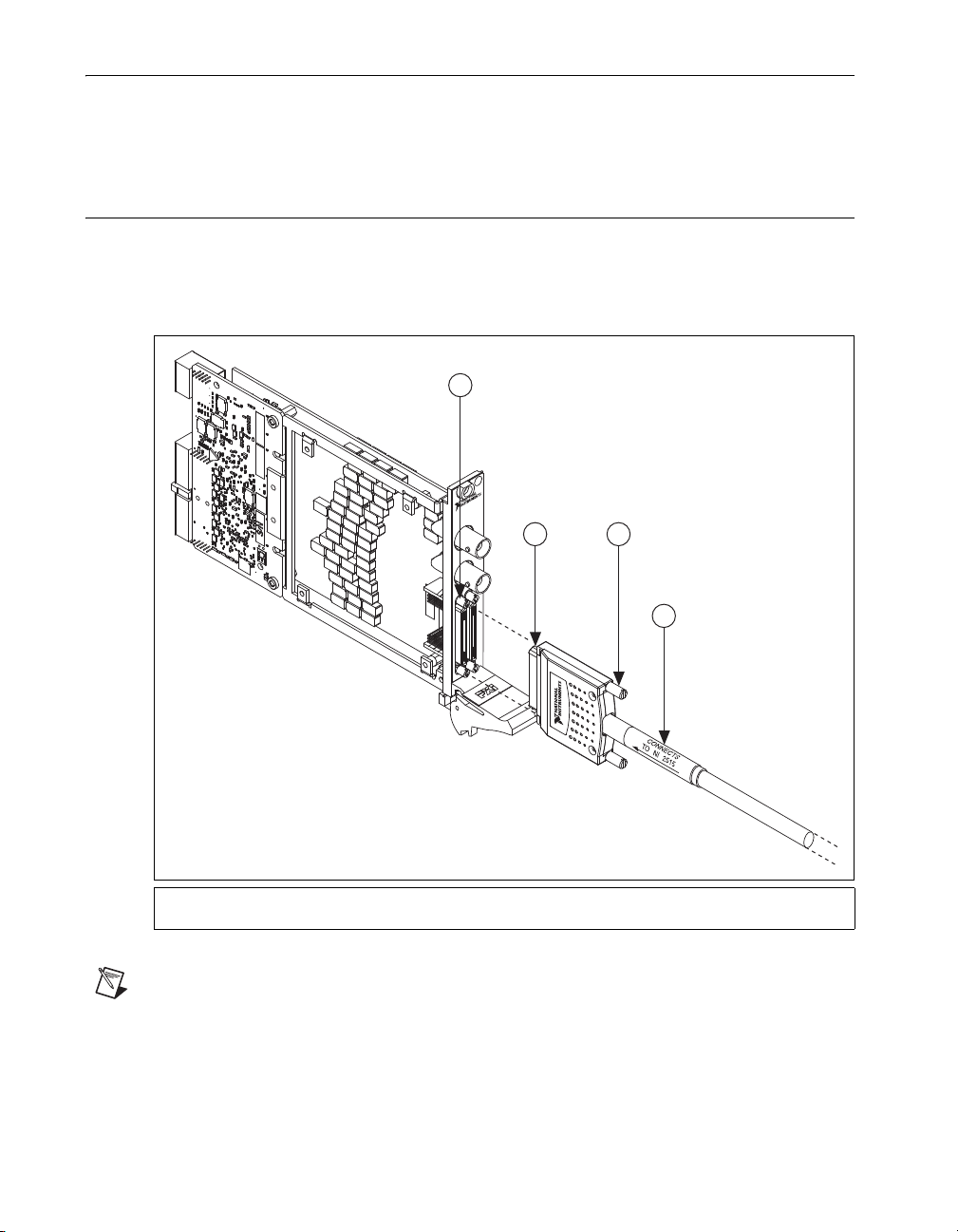
This guide describes how to connect and use the National Instruments SHC68-C68-D5 cable, which has
a maximum voltage rating of 30 VDC CAT I. Use this cable to connect the NI PXI/PXIe-2515 (NI 2515)
switch module to a supported NI high-speed DIO device. Refer to the NI Switches Help for a list of
supported NI high-speed DIO devices.
Caution Use only the NI SHC68-C68-D5 cable to connect the supported NI high-speed DIO device
to the NI 2515. The cable translates the pinout of the supported NI high-speed DIO device to the
HSDIO connector on the NI 2515 so that the pinout of the DUT connector on the NI 2515 matches
that of the supported NI high-speed DIO device.
Contents
Conventions ......................................................................................................................................... 1
What You Need to Get Started ............................................................................................................ 2
Getting Started with the NI SHC68-C68-D5 Cable............................................................................. 2
Cable Configuration............................................................................................................................. 3
Connectors ................................................................................................................................... 3
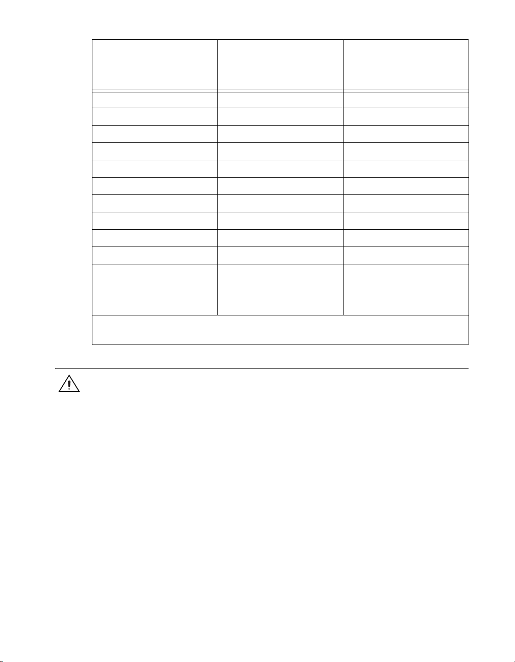
Specifications....................................................................................................................................... 5
Environment................................................................................................................................. 5
Conventions
The following conventions are used in this guide:
»The »symbol leads you through nested menu items and dialog box options to a final action.
The sequence File»Page Setup»Options directs you to pull down the File menu, select the
Page Setup item, and select Options from the last dialog box.
This icon denotes a note, which alerts you to important information.
This icon denotes a caution, which advises you of precautions to take to avoid injury, data loss,
or a system crash.
italic Italic text denotes variables, emphasis, a cross-reference, or an introduction to a key concept.
Italic text also denotes text that is a placeholder for a word or value that you must supply.
monospace Text in this font denotes text or characters that you should enter from the keyboard, sections
of code, programming examples, and syntax examples. This font is also used for the proper
names of disk drives, paths, directories, programs, subprograms, subroutines, device names,
functions, operations, variables, filenames, and extensions.
Ρ΅νιϋΠȂུࢊβȜΐ܄ȃ

NI SHC68-C68-D5 Cable Installation Instructions 2 ni.com
What You Need to Get Started
To use the cable, you need the following items:
❑NI SHC68-C68-D5 cable
❑NI 2515 switch module and documentation
Getting Started with the NI SHC68-C68-D5 Cable
Complete the following steps to connect the cable to the switch module and your application. Refer to
Figures 1 and 2 for illustrations of the cable, and refer to Figure 3 for an illustration of the connector.
1. Connect the cable connector labeled CONNECTS TO NI 2515 to the HSDIO connector on the
NI 2515 module as shown in Figure 1.
Figure 1. Connecting the Cable to the NI 2515
Note NI recommends placing your supported NI high-speed DIO device in the chassis slot
immediately to the left of the NI 2515. Use caution when inserting or removing a device immediately
to the left of the NI 2515 when the NI SHC68-C68-D5 cable is connected to the NI 2515, as the cable
connector may overlap slightly into the space of that slot.
2. Tighten the thumbscrews on the cable.
1 NI 2515 HSDIO Connector
2 NI SHC68-C68-D5 Connector
3 Thumbscrews
4CONNECTS TO NI 2515 Label
NI PXI-2515
32
1
4

©National Instruments Corporation 3 NI SHC68-C68-D5 Cable Installation Instructions
3. Connect the other end of the cable to your supported NI high-speed DIO device. Refer to Table 1
in the Cable Configuration section to determine how to connect signals to your application.
Figure 2. NI SHC68-C68-D5 Cable
4. Tighten the thumbscrews on the cable.
5. If you have not already done so, connect the NI 2515 to the rest of your system. Refer to the
NI Switches Help for more information about connecting the NI 2515 to your system.
Cable Configuration
Connectors
The cable connects two 68-position male VHDCI connectors. The connector labeled CONNECTS TO
NI 2515 provides connection to the switch module. The second connector provides connection to a
supported NI high-speed DIO device. Figure 3 shows the pinout for the connectors.
Use the pinout and the pin assignments listed in Table 1 to determine how to connect signals to your
application using the NI SHC68-C68-D5 cable.
Figure 3. NI SHC68-C68-D5 Mating Connector
1 NI SHC68-C68-D5 Connectors
2 Thumbscrews
3 Connects to Supported NI High-Speed DIO Device
4CONNECTS TO NI 2515 Label
CONNECTSTO NI 2515
3421 2 1
30 VDC CAT I
Pin 1
Pin 35 Pin 68
Pin 34

NI SHC68-C68-D5 Cable Installation Instructions 4 ni.com
Table 1. Pin Assignment for NI SHC68-C68-D5 Cable*
NI SHC68-C68-D5
Connector Pin Number
(Supported NI High-Speed
DIO Device Side) NI 2515 Signal
NI SHC68-C68-D5
Connector Pin Number
(NI 2515 Side)
65 ch0 38
31 ch1 4
63 ch2 40
29 ch3 6
61 ch4 42
27 ch5 8
59 ch6 44
25 ch7 10
57 ch8 46
23 ch9 12
55 ch10 48
21 ch11 14
53 ch12 50
19 ch13 16
51 ch14 52
17 ch15 18
49 ch16 54
15 ch17 20
47 ch18 56
13 ch19 22
45 ch20 58
11 ch21 24
43 ch22 60
9ch23 26
41 ch24 62
7ch25 28
39 ch26 64
5ch27 30
37 ch28 66

©National Instruments Corporation 5 NI SHC68-C68-D5 Cable Installation Instructions
Specifications
Caution Do not exceed the maximum voltage for your supported NI high-speed DIO device. Refer
to ni.com/manuals for the specifications document for your NI high-speed DIO device.
Maximum voltage ..................................................30 VDC CAT I
Maximum current ..................................................300 mA per pin
Weight ....................................................................199 g (7 oz)
Environment
Operating temperature ...........................................0 °C to 55 °C
Storage temperature ...............................................–20 °C to 70 °C
Relative humidity...................................................5% to 85%, noncondensing
Pollution Degree ....................................................2
Maximum altitude..................................................2,000 m
Indoor use only.
3ch29 32
35 ch30 68
1ch31 34
52 ctrl0 51
26 ctrl1 9
64 ctrl2 39
30 ctrl3 5
33 ctrl4 2
67 ctrl5 36
8, 60 RESERVED†27, 43
2, 4, 6, 10, 12, 14, 16, 18, 20,
22, 24, 28, 32, 34, 36, 38, 40,
42, 44, 46, 48, 50, 54, 56, 58,
62, 66, 68
GND 1, 3, 7, 11, 13, 15, 17, 19, 21,
23, 25, 29, 31, 33, 35, 37, 41,
45, 47, 49, 53, 55, 57, 59, 61,
63, 65, 67
* Refer to the NI Switches Help for a complete listing of channel names and pinouts.
†RESERVED signal is reserved by the NI 2515 for future use.
Table 1. Pin Assignment for NI SHC68-C68-D5 Cable* (Continued)
NI SHC68-C68-D5
Connector Pin Number
(Supported NI High-Speed
DIO Device Side) NI 2515 Signal
NI SHC68-C68-D5
Connector Pin Number
(NI 2515 Side)

National Instruments, NI, ni.com, and LabVIEW are trademarks of National Instruments Corporation. Refer to the Terms of Use section on
ni.com/legal for more information about National Instruments trademarks. Other product and company names mentioned herein are
trademarks or trade names of their respective companies. For patents covering National Instruments products/technology, refer to the appropriate
location: Help»Patents in your software, the patents.txt file on your media, or the National Instruments Patent Notice at ni.com/patents.
© 2009 National Instruments Corporation. All rights reserved. 375300A Oct09
Table of contents
Other NI Cables And Connectors manuals
Popular Cables And Connectors manuals by other brands

Philips
Philips SWA2707W Specifications

Burndy
Burndy Continental Industries thermOweld BRE-7 instructions

PCB Piezotronics
PCB Piezotronics 010G05 Installation and operating manual

Techly
Techly IDATA HDMI-4K4 user manual

SENKO
SENKO XP Fit Plus LC 900 mm instruction manual

CYP
CYP CH-526RXPL Operation manual