prevent unacceptable performance degradation, install and use this product in strict
accordance with the instructions in the product documentation.
Furthermore, any changes or modifications to the product not expressly approved
by National Instruments could void your authority to operate it under your local
regulatory rules.
Notice To ensure the specified EMC performance, operate this product
only with shielded cables and accessories. Do not use unshielded cables or
accessories unless they are installed in a shielded enclosure with properly
designed and shielded input/output ports and connected to the product
using a shielded cable. If unshielded cables or accessories are not properly
installed and shielded, the EMC specifications for the product are no
longer guaranteed.
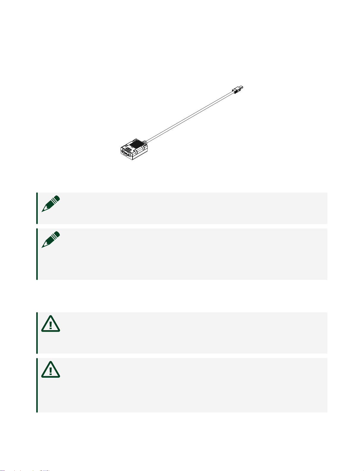
Mounting the TRC-8546
Caution The TRC-8546 is a thermally active device that dissipates heat.
Refer to the user manual of the host this device directly connects to for
specific information regarding thermal management. Not following
mounting requirements may aect the system ambient temperature
and/or the measurement accuracy of modules in the system.
Caution To meet thermal management requirements, do not zip tie more
than six cables in a bundle, and allow for air flow around the bundle. If
used with a cRIO or cDAQ chassis, mount all cables at least 152 mm
(6.0 in.) from the chassis and do not mount more than six cables directly
beneath the chassis.
You can route and strain relieve the TRC-8546 similarly to ordinary cables. You also
can panel mount it using its removable jackscrews, zip tie, or screw mount it. The
screw mounting holes support #6 and M3 screws spaced 35.56 mm (1.400 in.)
center-to-center, with minimum length of 23 mm (7/8 in.). The TRC-8546 supports
zip ties up to 5.33 mm (0.210 in.) wide.
ni.com
6
TRC-8546 Getting Started