NI cRIO-9036 User manual

cRIO-9036
Getting Started
2022-07-06

Contents
Overview. . . . . . . . . . . . . . . . . . . . . . . . . . . . . . . . . . . . . . . . . . . . . . . . . . . . . . . . . . . . . . . . . . . . . . 3
Safety Guidelines. . . . . . . . . . . . . . . . . . . . . . . . . . . . . . . . . . . . . . . . . . . . . . . . . . . . . . . . . . . . 3
Electromagnetic Compatibility Guidelines. . . . . . . . . . . . . . . . . . . . . . . . . . . . . . . . . . . . . . 5
Preparing the Environment. . . . . . . . . . . . . . . . . . . . . . . . . . . . . . . . . . . . . . . . . . . . . . . . . . . 7
Unpacking the Kit. . . . . . . . . . . . . . . . . . . . . . . . . . . . . . . . . . . . . . . . . . . . . . . . . . . . . . . . . . . . 7
Verifying the Kit Contents. . . . . . . . . . . . . . . . . . . . . . . . . . . . . . . . . . . . . . . . . . . . . . . . . . . . . 8
Installing Soware on the Host Computer. . . . . . . . . . . . . . . . . . . . . . . . . . . . . . . . . . . . . . 8
Installing C Series Modules. . . . . . . . . . . . . . . . . . . . . . . . . . . . . . . . . . . . . . . . . . . . . . . . . . . . 8
Removing C Series Modules. . . . . . . . . . . . . . . . . . . . . . . . . . . . . . . . . . . . . . . . . . . . . . 9
Connecting the cRIO-9036. . . . . . . . . . . . . . . . . . . . . . . . . . . . . . . . . . . . . . . . . . . . . . . . . . . . 9
Connecting the cRIO-9036 to Ground. . . . . . . . . . . . . . . . . . . . . . . . . . . . . . . . . . . . . 9
Connecting the cRIO-9036 to Power. . . . . . . . . . . . . . . . . . . . . . . . . . . . . . . . . . . . . 10
Connecting the cRIO-9036 to the Host Computer. . . . . . . . . . . . . . . . . . . . . . . . . . 13
Configuring the System in Measurement & Automation Explorer (MAX). . . . . . . . . . . 14
Setting a System Password. . . . . . . . . . . . . . . . . . . . . . . . . . . . . . . . . . . . . . . . . . . . . 14
Installing Soware on the cRIO-9036. . . . . . . . . . . . . . . . . . . . . . . . . . . . . . . . . . . . . 15
Troubleshooting the cRIO-9036. . . . . . . . . . . . . . . . . . . . . . . . . . . . . . . . . . . . . . . . . . . . . . 16
The cRIO-9036 is Not Communicating with the Network. . . . . . . . . . . . . . . . . . . 16
System Reset. . . . . . . . . . . . . . . . . . . . . . . . . . . . . . . . . . . . . . . . . . . . . . . . . . . . . . . . . . 18
STATUS LED Indicators. . . . . . . . . . . . . . . . . . . . . . . . . . . . . . . . . . . . . . . . . . . . . . . . . 18
NI cRIO-9036 Sync Firmware Licensing. . . . . . . . . . . . . . . . . . . . . . . . . . . . . . . . . . . . . . . . 19
ni.com
2
cRIO-9036 Getting Started

Overview
This document describes how to begin using the National Instruments cRIO-9036.
In this document, the NI cRIO-9036 and NI cRIO-9036 Sync are inclusively referred to
as the cRIO-9036.
For more information about timing and synchronization capabilities of NI cRIO-9036
Sync, visit ni.com/info and enter the Info Code .
Safety Guidelines
Caution Observe all instructions and cautions in the user documentation.
Using the model in a manner not specified can damage the model and
© National Instruments 3
cRIO-9036 Getting Started

compromise the built-in safety protection. Return damaged models to NI
for repair.
Attention Suivez toutes les instructions et respectez toutes les mises
en garde de la documentation utilisateur. L'utilisation d'un modèle de
toute autre façon que celle spécifiée risque de l'endommager et de
compromettre la protection de sécurité intégrée. Renvoyez les modèles
endommagés à NI pour réparation.
Safety Guidelines for Hazardous Locations
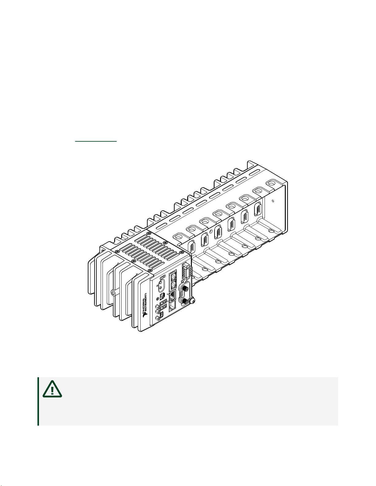
The cRIO-9036 is suitable for use in Class I, Division 2, Groups A, B, C, D, T4
hazardous locations; Class I, Zone 2, AEx nA IIC T4 Gc and Ex nA IIC T4 Gc hazardous
locations; and nonhazardous locations only. Follow these guidelines if you are
installing the cRIO-9036 in a potentially explosive environment. Not following these
guidelines may result in serious injury or death.
Caution Do not disconnect the power supply wires and connectors from
the controller unless power has been switched o.
Caution Do not disconnect I/O-side wires or connectors unless power has
been switched o or the area is known to be nonhazardous.
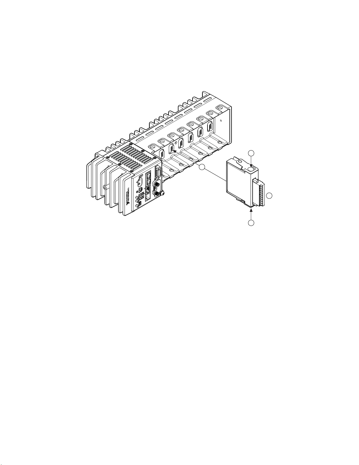
Caution Do not remove modules unless power has been switched o or
the area is known to be nonhazardous.
Caution Substitution of components may impair suitability for Class I,
Division 2, or Zone 2.
Caution The system must be installed in an enclosure certified for the
intended hazardous (classified) location, having a tool secured cover/door,
where a minimum protection of at least IP54 is provided.
ni.com
4
cRIO-9036 Getting Started

Special Conditions for Hazardous Locations Use in Europe and
Internationally
The cRIO-9036 has been evaluated as Ex nA IIC T4 Gc equipment under
DEMKO 12ATEX 1202658X and is IECEx UL 14.0089X certified. Each device is
marked II 3G and is suitable for use in Zone 2 hazardous locations, in ambient
temperatures of -40 °C ≤ Ta ≤ 70 °C.
Caution Transient protection shall be provided that is set at a level not
exceeding 140% of the peak rated voltage value of 85 V at the supply
terminals to the equipment.
Caution The system shall only be used in an area of not more than
Pollution Degree 2, as defined in IEC/EN 60664-1.
Caution The system shall be mounted in an ATEX/IECEx-certified
enclosure with a minimum ingress protection rating of at least IP54 as
defined in IEC/EN 60079-15.
Caution The enclosure must have a door or cover accessible only by the
use of a tool.
Electromagnetic Compatibility Guidelines
This product was tested and complies with the regulatory requirements and limits
for electromagnetic compatibility (EMC) stated in the product specifications. These
requirements and limits provide reasonable protection against harmful interference
when the product is operated in the intended operational electromagnetic
environment.
This product is intended for use in industrial locations. However, harmful
interference may occur in some installations, when the product is connected to a
peripheral device or test object, or if the product is used in residential or
commercial areas. To minimize interference with radio and television reception and
© National Instruments 5
cRIO-9036 Getting Started

prevent unacceptable performance degradation, install and use this product in strict
accordance with the instructions in the product documentation.
Furthermore, any changes or modifications to the product not expressly approved
by National Instruments could void your authority to operate it under your local
regulatory rules.
Caution To ensure the specified EMC performance, operate this product
only with shielded cables and accessories. The DC power input cables may
be unshielded.
Caution To ensure the specified EMC performance, you must use an
isolated cable with the RS-485 serial port, such as NI part number
184428-01.
Caution To ensure the specified EMC performance, the length of any
cable connected to the video and V2 ports must be no longer than
3 m (10 ). The length of any cable connected to the RS-232 and RS-485
ports must be no longer than 30 m (100 ). The length of any cable
connected to the USB host ports must be no longer than 5 m (16 ).
Caution The USB device port is intended only for use in device
configuration, application deployment, debug, and maintenance.
Caution To ensure the specified EMC performance, product installation
requires either special considerations or user-installed, add-on devices.
Refer to the following sections for more information.
Related tasks
■Connecting the cRIO-9036 to Ground
■Connecting the cRIO-9036 to Power
■Connecting the to Ground
■Connecting the to Power
ni.com
6
cRIO-9036 Getting Started

Special Conditions for Marine Applications
Some products are approved for marine (shipboard) applications. To verify marine
approval certification for a product, visit ni.com/product-certifications, search by
model number, and click the appropriate link.
Notice In order to meet the EMC requirements for marine applications,
install the product in a shielded enclosure with shielded and/or filtered
power and input/output ports. In addition, take precautions when
designing, selecting, and installing measurement probes and cables to
ensure that the desired EMC performance is attained.
Preparing the Environment
Ensure that the environment in which you are using the cRIO-9036 meets the
following specifications.
Operating temperature (IEC 60068-2-1, IEC 60068-2-2) -40 °C to 70 °C
Operating humidity (IEC 60068-2-78) 10% RH to 90% RH, noncondensing
Pollution Degree 2
Maximum altitude 5,000 m
Indoor use only.
Note Refer to the device specifications on ni.com/manuals for complete
specifications.
Unpacking the Kit
Notice To prevent electrostatic discharge (ESD) from damaging the
device, ground yourself using a grounding strap or by holding a grounded
object, such as your computer chassis.
© National Instruments 7
cRIO-9036 Getting Started

1. Touch the antistatic package to a metal part of the computer chassis.
2. Remove the device from the package and inspect the device for loose
components or any other sign of damage.
Notice Never touch the exposed pins of connectors.
Note Do not install a device if it appears damaged in any way.
3. Unpack any other items and documentation from the kit.
Store the device in the antistatic package when the device is not in use.
Verifying the Kit Contents
Verify that the following items are included in the cRIO-9036 kit.
Installing Soware on the Host Computer
Before using the cRIO-9036, you must install the following application soware and
device drivers on the host computer in this order:
Sequence cRIO-9036 cRIO-9036 Sync
1 LabVIEW 2014 SP1 or later LabVIEW 2016 or later
2 LabVIEW Real-Time Module 2014 SP1 LabVIEW Real-Time Module 2016 or later
3 LabVIEW FPGA Module 2014 SP1 or
later[1] LabVIEW FPGA Module 2016 or later[1]
4 NI CompactRIO Device Drivers
February 2015 or later
NI CompactRIO Device Drivers August 2016
or later
For minimum soware support information, visit ni.com/info and enter the Info
Code swsupport.
1 LabVIEW FPGA Module is not required when using Scan Interface mode. To
program the user-accessible FPGA on the cRIO-9036, LabVIEW FPGA Module is
required.
ni.com
8
cRIO-9036 Getting Started

Installing C Series Modules
Complete the following steps to install a C Series module.
3
2
2
1
1. Verify that power is not connected to the I/O connector(s) on the C Series
module. If the system is in a nonhazardous location, the cRIO-9036 can be
powered on when you install modules.
2. Press the latches on the C Series module.
3. Align the C Series module with a slot and seat it in the slot until the latches
lock in place.
Removing C Series Modules
Verify that power is not connected to the I/O connector(s) on the C Series module
before you remove a module from the cRIO-9036. If the system is in a nonhazardous
location, the cRIO-9036 can be powered on when you remove modules.
Connecting the cRIO-9036
The cRIO-9036 has the following connectors, LEDs, and buttons.
© National Instruments 9
cRIO-9036 Getting Started

Connecting the cRIO-9036 to Ground
You must connect the cRIO-9036 grounding terminal to the grounding electrode
system of the facility.
What to Use
■Ring lug
■Wire, 1.3 mm2 (16 AWG) or larger
■Screwdriver, Phillips #2
What to Do
Complete the following steps to ground the cRIO-9036.
1. Attach the ring lug to the wire.
2. Remove the grounding screw from the grounding terminal on the cRIO-9036.
3. Attach the ring lug to the grounding terminal.
4. Tighten the grounding screw to 0.5 N · m (4.4 lb · in.) of torque.
5. Attach the other end of the wire to the grounding electrode system of your
facility using a method that is appropriate for your application.
Caution If you use shielded cabling to connect to a C Series module with
a plastic connector, you must attach the cable shield to the chassis
grounding terminal using 1.3 mm2 (16 AWG) or larger wire. Attach a ring
lug to the wire and attach the wire to the chassis grounding terminal.
Solder the other end of the wire to the cable shield. Use shorter wire for
better EMC performance.
For more information about ground connections, visit ni.com/info and enter the
Info Code emcground.
ni.com
10
cRIO-9036 Getting Started

Connecting the cRIO-9036 to Power
The cRIO-9036 requires a 9 V to 30 V external power supply. The cRIO-9036 filters
and regulates the supplied power and provides power for the C Series modules. The
cRIO-9036 has a primary power input, V1, and a secondary power input, V2.
The POWER LED on the cRIO-9036 indicates which power input is in use, as shown in
the following table.
LED Color LED Pattern Indication
Green Solid The cRIO-9036 is powered from the V1 input.
Yellow Solid The cRIO-9036 is powered from the V2 input.
—O The cRIO-9036 is powered o.
Table 1. POWER LED Indicators
Caution Do not connect V2 to a DC mains supply or to any supply that
requires a connecting cable longer than 3 m(10 ). A DC mains supply is a
local DC electricity supply network in the infrastructure of a site or
building.
What to Use
■Ferrite
■Screwdriver, 2.54 mm (0.10 in.) flathead
■Primary power supply, 9 V to 30 V, 46 W minimum
■(Optional) Secondary power supply, 9 V to 30 V, 46 W minimum
NI recommends the power supplies listed in the following table for the cRIO-9036.
Power Supply Part Number
NI PS-15 Industrial Power Supply (24 V DC, 5 A, 100 V AC to 120 V AC/200 V AC to
240 V AC input)
781093-01
NI PS-10 Desktop Power Supply (24 V DC, 5 A, 100 V AC to 120 V AC/200 V AC to
240 V AC input)
782698-01
Table 2. NI Power Supplies
© National Instruments 11
cRIO-9036 Getting Started

What to Do
Complete the following steps to connect a power supply to the cRIO-9036.
1. Ensure that your power supply is powered o.
2. Install the ferrite on the negative and positive leads of the power supply, as
shown in the following figure.
Figure 1. Installing a Ferrite on the Power Leads
2
1
1. Pass the leads through the ferrite twice, leaving 50 mm to 75 mm (2 in.
to 3 in.) between the ferrite and the end of the leads.
2. Close the ferrite around the leads.
3. Remove the power connector from the cRIO-9036.
Caution Do not tighten or loosen the terminal screws on the power
connector while the cRIO-9036 is powered on.
4. Connect the primary power supply and optional secondary power supply to
the power connector, as shown in the following figure.
Figure 2. cRIO-9036 Power Connections
Power Connector
V2
C
C
V1
Primary Power Supply
+
–
–
+
Secondary Power Supply
FerriteFerrite
ni.com
12
cRIO-9036 Getting Started

Note The C terminals are internally connected to each other.
5. Tighten the terminal screws on the power connector to 0.20 N · m to 0.25 N · m
(1.8 lb · in. to 2.2 lb · in.) of torque.
6. Install the power connector on the front panel of the cRIO-9036.
7. Tighten the power connector screw flanges to 0.20 N · m to 0.25 N · m
(1.8 lb · in. to 2.2 lb · in.) of torque.
8. Power on the primary power supply and optional secondary power supply.
Powering On the cRIO-9036
When you power on the cRIO-9036 for the first time, the device boots into safe
mode. The POWER LED illuminates, the STATUS LED illuminates briefly, and then the
STATUS LED blinks twice every few seconds.
Related reference
■STATUS LED Indicators
Connecting the cRIO-9036 to the Host Computer
Complete the following steps to connect the cRIO-9036 to the host computer using
the USB device port.
1. Power on the host computer.
2. Connect the cRIO-9036 to the host computer using the USB A-to-B cable.
Caution NI requires the use of a locking USB cable (157788-01) to
meet the shock and vibration specifications. Refer to the
specifications on ni.com/manuals for shock and vibration
specifications.
The device driver soware automatically detects the cRIO-9036. If the device
driver soware does not detect the cRIO-9036, verify that you installed the
appropriate NI soware in the correct order on the host computer.
© National Instruments 13
cRIO-9036 Getting Started

Tip You can also use the Ethernet port to connect directly to the host
computer or network. Refer to the user manual on ni.com/manuals for
more information about Ethernet connections.
Related information
■Installing Soware on the Host Computer
Configuring the System in Measurement & Automation
Explorer (MAX)
Complete the following steps to find the system in MAX.
1. Launch MAX on the host computer.
2. Expand Remote Systems in the configuration tree and locate your system.
3. Select your target.
Tip MAX lists the system under the model number followed by the
serial number, such as NI-cRIO-9036-1856AAA.
Setting a System Password
Complete the following steps to set a system password.
Note The default username for the cRIO-9036 is admin. There is no default
password for the cRIO-9036, so you must leave the password field blank
when logging in until you set a system password.
1. Right-click your system and select Web Configuration.
The NI Web-Based Configuration and Monitoring utility opens in your default
browser and is where you set the password. If you have not installed Microso
Silverlight, NI Web-based Configuration & Monitoring prompts you to do so.
2. Enter a unique name for your system in the Hostname field.
ni.com
14
cRIO-9036 Getting Started

3. Click the Security Configuration icon.
4. Click Login.
5. In the Login dialog box, enter the username admin and leave the password
field blank.
6. Click OK.
7. Click Change Password.
8. Enter and re-enter a new password.
9. Click OK.
10. Click Save.
11. Click OK to confirm you are changing the password.
Caution NI cannot recover lost system passwords. If you forget the
password, you must contact NI and reformat the controller.
Installing Soware on the cRIO-9036
Complete the following steps to install soware on the cRIO-9036.
1. In MAX, expand your system under Remote Systems.
2. Right-click Software.
3. Select Add/Remove Software to launch the LabVIEW Real-Time Soware
Wizard.
Tip You must log in if you set a system password.
4. Select the recommended soware set for your LabVIEW and NI-RIO Device
Drivers versions.
5. Click Next.
6. Select NI Scan Engine from the soware add-ons.
Select any additional soware to install. If you plan on using the cRIO-9036
with the LabVIEW FPGA Module, you can click Next. Click NI Scan Engine if you
plan on using the cRIO-9036 without the LabVIEW FPGA Module.
© National Instruments 15
cRIO-9036 Getting Started

Tip You can use this wizard at anytime to install additional soware.
7. Click Next.
8. Verify that the summary of soware to install is correct.
9. Click Next to start the installation.
10. Click Finish when the installation is complete.
Troubleshooting the cRIO-9036
The cRIO-9036 is Not Communicating with the Network
■Ensure that the USB connections between the cRIO-9036 and the host
computer and the Ethernet connections between the host computer and the
router are secure.
■Configure the IP and other network settings by completing the following
steps.
1. Use a USB A-to-B cable to connect the cRIO-9036 USB device port to a
host computer. The USB driver creates a virtual network interface card
and assigns an IP address to the cRIO-9036 in the format of 172.22.11.x.
2. In MAX, expand your system under Remote Systems.
3. Select the Network Settings tab to configure the IP and other network
settings.
4. (Optional) Use the RJ-45 Ethernet port 1 to reconnect the cRIO-9036 to
the host computer. The cRIO-9036 attempts to initiate a DHCP network
connection at powerup.
Note If the cRIO-9036 cannot obtain an IP address, it connects
to the network with a link-local IP address with the form
169.254.x.x. The host computer communicates with the
cRIO-9036 over a standard Ethernet connection.
■Ensure that you have the correct version of NI CompactRIO Device Drivers
installed on the host computer. Visit ni.com/info and enter the Info Code
ni.com
16
cRIO-9036 Getting Started

swsupport for the minimum supported versions of LabVIEW and
NI CompactRIO Device Drivers.
Tip If you have recently upgraded LabVIEW, you must reinstall NI
CompactRIO Device Drivers.
■Ensure that the NI USBLAN adapter is recognized in the Device Manager. On
Windows 7, select Start » Control Panel » Device Manager » Network
adapters » National Instruments » USBLAN adapter. If the USBLAN adapter is
not recognized, you must reinstall NI CompactRIO Device Drivers.
■Temporarily disable any network firewalls or other security soware.
Verify the System IP Configuration
1. Put the cRIO-9036 in safe mode and enable the RS-232 serial port by holding
the RESET button down for 5 seconds.
The STATUS LED starts blinking three times every few seconds.
2. Use the RS-232 serial port terminal to read the IP address, or connect a
monitor to the mini DisplayPort to view the IP address.
Note Refer to the user manual on ni.com/manuals for more
information about serial port configuration.
3. Set a new DHCP connection by holding the RESET button down for 5 seconds.
The STATUS LED repeats the same behavior from Step 1.
If the cRIO-9036 fails to set a new DHCP address, it assigns itself a link-local IP
address. If the DHCP connection is successful and appropriate for your
application, skip to Step 6.
4. In MAX, expand your system under Remote Systems.
5. Select the Network Settings tab to configure the IP and other network
settings.
6. Reboot the cRIO-9036 by pressing the RESET button.
© National Instruments 17
cRIO-9036 Getting Started

Configure the Windows Firewall
■Add an exception for MAX to your network firewall or other security soware
by completing the following steps:
1. On Windows 7, select Start » Control Panel » System and Security »
Windows Firewall » Allow a program through Windows Firewall.
2. Click Allow another program.
3. Select Measurement & Automation.
4. Click Add.
5. Click OK.
■Ensure that UDP port 44525 is open to communication on the host
computer. If you are using an intelligent switch on the network, ensure that it
is not disabling UDP port 44525.
System Reset
The following figure shows the reset behavior of the cRIO-9036.
Figure 3. Reset Button Behavior
Press and hold RESET button for ≥ 5 s
Press and hold RESET button for < 5 s
Run Mode
Safe Mode
Press and hold RESET button for < 5 s
Press and hold RESET button for ≥ 5 s
Press and hold
RESET button for ≥ 5 s
Press and hold
RESET button for < 5 s
• Console Out enabled
• Network settings reset
• RT Startup App disabled
• FPGA Startup App disabled
• Console Out enabled
• RT Startup App disabled
• FPGA Startup App disabled
Safe Mode
STATUS LED Indicators
The following table describes the STATUS LED indicators.
ni.com
18
cRIO-9036 Getting Started

LED
Color
LED Pattern Indication
Yellow Blinks twice and
pauses
The cRIO-9036 is in safe mode. Soware is not installed, which is the
factory default state, or soware has been improperly installed on
the cRIO-9036.
An error can occur when an attempt to upgrade the soware is
interrupted. Reinstall soware on the cRIO-9036. Refer to the
Measurement & Automation Explorer (MAX) Help for information
about installing soware on the cRIO-9036.
Blinks three times
and pauses
The cRIO-9036 is in user-directed safe mode, or the cRIO-9036 is in
install mode to indicate that soware is currently being installed.
This pattern may also indicate that the user has forced the
cRIO-9036 to boot into safe mode by pressing the reset button for
longer than five seconds or by enabling safe mode in MAX. Refer to
the Measurement & Automation Explorer (MAX) Help for
information about safe mode.
Blinks four times
and pauses
The cRIO-9036 is in safe mode. The soware has crashed twice
without rebooting or cycling power between crashes.
Continuously
blinks
The cRIO-9036 has not booted into NI Linux Real-Time. The
cRIO-9036 either booted into an unsupported operating system, was
interrupted during the boot process, or detected an unrecoverable
soware error.
On momentarily The cRIO-9036 is booting. No action required.
Red Continuously
blinks
This indicates a hardware error. An internal power supply has failed.
Check front-panel I/O and C Series module connections for shorts.
Remove any shorts and cycle power the cRIO-9036. If the problem
persists, contact NI.
—O The cRIO-9036 is in run mode. Soware is installed and the
operating system is running.
Table 3. STATUS LED Indicators
NI cRIO-9036 Sync Firmware Licensing
Soware is licensed pursuant to the soware license agreements provided with the
soware or, in the absence of such license agreements, the National Instruments
Soware License Agreement available at ni.com/legal at the time of purchase.
© National Instruments 19
cRIO-9036 Getting Started
Table of contents
Other NI PCI Card manuals