Getting Started with the NI 9502 and AKM Motors 6 ni.com
Connecting and Using the NI 9502 in Trapezoidal Commutation Mode
This section explains how to connect and use the NI 9502 module in Trapezoidal commutation mode,
using an installed example to help you set up and configure your system.
What You Need to Get Started
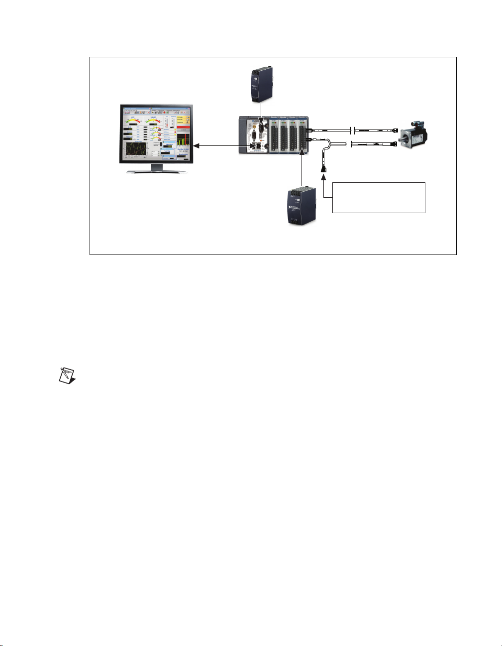
You need the following items to get started.
Hardware
❑NI 9502 C Series brushless servo drive module
❑NI CompactRIO real-time controller
❑24 V power supply (such as the NI PS-15) for the CompactRIO controller
(NI part number 781093-01)
❑24 V power supply (such as the NI PS-16) for the NI 9502 module
(NI part number 781094-01)
Note NI recommends the NI PS-16 power supply, which is designed for motor bus power, for use
with the NI 9502 module. Refer to Regeneration Consideration Using the NI C Series Drive Modules
at zone.ni.com for more information.
❑5 V power supply (such as the NI PS-6) for the Hall Effect sensors
(NI part number 780577-01)
Note If you are connecting the optional encoder and using an NI 9411 C Series module for encoder
connections, you can use the +5 V output on the NI 9411 module to power the encoder and Hall
Effect sensors on the NI AKM motor.
❑Ethernet connection and cable for the CompactRIO controller
❑NI 9502 to AKM Cable
(NI part number 153108-03)
❑NI AKM servo motor
❑(Optional) NI 9411 C Series module for encoder connections and +5 V output
(NI part number 779005-01)
❑(Optional) NI 9935 15pin D-Sub connector kit for connecting the NI 9411
(NI part number 779016-01)
Software
❑LabVIEW 2011 or later
❑LabVIEW 2011 Real-Time Module or later
❑NI-RIO 4.0.0 or later with CompactRIO Module Support 4.0.1 installed
❑(Optional) LabVIEW NI SoftMotion Module 2011 f1 or later
Note LabVIEW NI SoftMotion Module Premium provides FPGA Motor Control VIs that you can
use with the NI 9502. Your LabVIEW Platform DVD includes a free 30-day evaluation of
NI SoftMotion Module Premium that you can install. Refer to ni.com/info and enter nismpkg
for more information about the NI SoftMotion Module.