Niagara SmartPD User manual

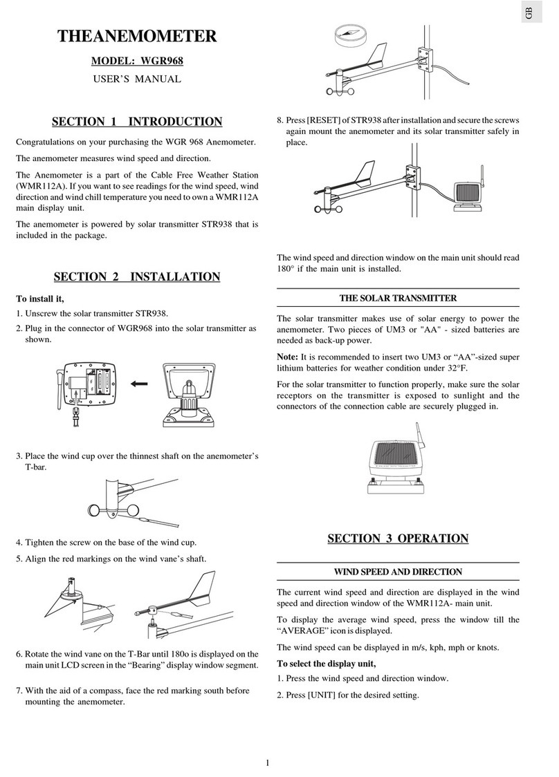
SmartPD Meter
Installation & Operation Manual
®
IOM
M30218 Rev. A


SmartPD Meter
Installation & Operation Manual
CONTENTS
®
I. HANDLING & STORAGE ......................................................................................................................... 1
Inspection and Handling
Disposal and Recycling
Storage
II. GENERAL SAFETY.................................................................................................................................. 2
Authorized Personnel
Use
Misuse
III. PRODUCT DESCRIPTION ...................................................................................................................... 3
Function
Applications
Features
TechnicalSpecications
Approvals
Temperature and Accuracy Charts
Figure 1. SND Ambient vs Process Temperature Limit
Figure 2. SOP Ambient vs Process Temperature
Figure 3. Typical Accuracy Curve (Water Calibration)
Pressure Drop Charts
Figure 4. Model SND Line Size B - 0.75” Bore
Figure 5. Model SND Line Size C - 1.00” Bore
Figure 6. Model SND Line Size D - 1.25” Bore
Figure 7. Model SND Line Size F - 1.50” Bore
Figure 8. Model SND Line Size G - 2.00” Bore
Figure 9. Model SOP Line Size C - 1.00” Bore
Figure 10. Model SOP Line Size G - 2.00” Bore
IV. MECHANICAL INSTALLATION.............................................................................................................. 10
Mounting Considerations
Nutating Disc and Oscillating Piston Installation
Figure11.TypicalComponentConguration
Remote Enclosure Installation
Figure 12. Remote Enclosure
V. ELECTRICAL INSTALLATION ............................................................................................................... 12
Integral Transmitter
Figure 13. Integral Transmitter Wiring
Figure 14. Maximum Load Resistance
Remote Transmitter
Figure 15. SmartPD Remote Wiring Diagram

HART Communication
Figure 16. HART Wiring
VI. SET-UP ............................................................................................................................................ 15
Transmitter
Display Description
Resetting Total Mode
Accessing Simulate Mode
Accessing Program Mode
Program Mode Information
Flow Type
Rate Unit
Total Unit
Range Set
Custom Scale
Set Cal
Decimal
Special
Direction
VII. MAINTENANCE ..................................................................................................................................... 20
Preventative Maintenance
VIII. TROUBLESHOOTING........................................................................................................................... 21
IX. DIMENSIONAL DRAWINGS.................................................................................................................. 23
SAFETY SYMBOLS
WARNING:
IDENTIFIES CONDITIONS OR PROCEDURES, WHICH IF NOT
FOLLOWED, COULD RESULT IN SERIOUS INJURY. RISK OF
ELECTRICAL SHOCK.
CAUTION:
IDENTIFIES CONDITIONS OR PROCEDURES, WHICH IF NOT
FOLLOWED, COULD RESULT IN SERIOUS DAMAGE OR FAILURE OF
THE EQUIPMENT.

1
www.niagarameters.com
®
M30218 Rev. A
SmartPD Meter
I. HANDLING AND STORAGE
SAVE THESE INSTRUCTIONS
INSPECTION AND HANDLING
Do not dispose of the carton or packing materials.
Each package should be inspected upon receipt for damage that may have occurred due to mishandling during
shipping. If the unit is received damaged, notify the carrier or the factory for instructions. Failure to do so may
void your warranty. If you have any problems or questions, consult Customer Support at 800-778-9251.
DISPOSAL AND RECYCLING
This product can be recycled by specialized companies and must not be disposed of in a municipal collection
site. If you do not have the means to dispose of properly, please contact Customer Support for return and
disposal instructions or options.
STORAGE
If the device is not scheduled for immediate installation following delivery, the following steps should be
observed:
1. Following inspection, repackage the unit into its original packaging.
2. Select a clean dry site, free of vibration, shock and impact hazards.
3. If storage will be extended longer than 30 days, the unit must be stored at temperatures between
32º and 158º F (0º to 70° C) in non-condensing atmosphere with humidity less than 85%.
CAUTION: DO NOT STORE A NON-POWERED UNIT OUTDOORS FOR A PROLONGED PERIOD.

2
www.niagarameters.com
®
M30218 Rev. A
II. GENERAL SAFETY
AUTHORIZED PERSONNEL
Allinstructionsdescribedinthedocumentmustbeperformedbyauthorizedandqualiedservicepersonnel
only. Before installing the unit, please read these instructions and familiarize yourself with the requirements and
functions of the device. The required personal protective equipment must always be worn when servicing this
device.
USE
The device is solely intended for use as described in this manual. Reliable operation is ensured only if the
instrumentisusedaccordingtothespecicationsdescribedinthisdocument.Forsafetyandwarranty
reasons,useofaccessoryequipmentnotrecommendedbythemanufacturerandanymodicationofthis
deviceisexplicitlyforbidden.Allservicingofthisequipmentmustbeperformedbyqualiedservicepersonnel
only. This device should be mounted in locations where it will not be subject to tampering by unauthorized
personnel.
MISUSE
Improper use or installation of this device may cause the following:
• Personalinjuryorharm
• Applicationspecichazardssuchasvesseloverll
• Damagetothedeviceorsystem
If any questions or problems arise during installation of this equipment, please contact Customer Support at
800-778-9251.

3
www.niagarameters.com
®
M30218 Rev. A
III. PRODUCT DESCRIPTION
FUNCTION
TheSmartPDisavolumetricmeterthatprovidestotalvolumeandowratemeasurementsbywayofan
electronic transmitter. This 2-wire device provides an analog response by way of a 4-20 mA signal, digital
feedback via HART communication, and a visual indication of change on an LCD. There are two variations of this
meter; the SmartPD nutating disc (SND), and the SmartPD oscillating piston (SOP).
TheSmartPDmeteriscapableofmeasuringvolumeandowrateforawiderangeofmaterialsinanumberof
different industries. It is a compact, space saving design that eliminates the need for upstream and downstream
piperequirements.Itisofferedinawiderangeofmaterials,nishesandlinesizes.
APPLICATIONS
• ChemicalProcessing
• Industrialmanufacturing
• Paint
• Pulpandpaper
• FoodProcessing
• ConcreteBatching
• Cosmetic
• Pharmaceutical
• Agricultural
• Automotive
FEATURES
• 2wirelooppowered
• 4-20mAproportionaltoow
• HARTCommunication
• 2linedigitalLCDdisplay
• Remotedistanceupto50’(15m)
• Providestotalandowrates
• Wideprocesstemperaturerating

4
www.niagarameters.com
®
M30218 Rev. A
TECHNICAL SPECIFICATIONS
FUNCTIONAL
Fluid Types Liquids
Temperature See Temperature Graphs
PERFORMANCE
Accuracy SND Models: ± 1.5%
SOP Models: ± 0.5%
Totalizer Repeatability < 0.25%
Flow Rate Repeatability 0.25%
Typical Update Rate of Display 1 Second
Typical Update Rate of 4-20 mA Output 100 mS, 8 mA/second max
PHYSICAL
Flow Direction Unidirectional
Housing/Flanges 1.0 to 2.5”, NPT and Flanges
Pipe Requirements Typical Straight
Process Connections Model Dependent NPT or Flange
Electrical Connections 3/4” NPT
Supply Voltage 24 VDC ± 10%
Line Size Nutating Disc (SND Models): 0.75, 1.0, 1.25, 1.5, 2.0”
Oscillating Piston (SOP Models): 1.0 and 2.0”
Mounting Position Horizontal
Typical Straight Pipe Requirements None
APPROVALS
CE
TEMPERATURE AND ACCURACY CHARTS
Figure 1. SND Ambient vs Process Temperature Limit

5
www.niagarameters.com
®
M30218 Rev. A
Figure 2. SOP Ambient vs Process Temperature
SOP Typical Accuracy Curve
(Water Calibration)
Notes: 1. Meter accuracy validated at 0%, 50% and 100%
owrates.
2. Repeatability of system is measured at 0.25%.
Figure 3. SND Typical Accuracy Curve
(Water Calibration)
Notes: 1.Meteraccuracyvalidatedat0%,10%and50%owrates.
2. Repeatability of system is measured at 0.5%.
FAMILY OIL CALIBRATION
(gpm)
WATER CALIBRATION
(gpm)
SND Line Size B 1-20 2-20
SND Line Size C 2-30 3-30
SND Line Size D 3-50 5-50
SND Line Size F 5-100 8-100
SND Line Size G 8-120 8-100
SOP Line Size C 7-70 7-70
SOP Line Size G 15-150 15-150
Notes: 1.Actualowrangesvaryfordifferentprocessmaterials.
Contact the manufacturer for instructions on selecting an appropriate meter for your application

6
www.niagarameters.com
®
M30218 Rev. A
PRESSURE DROP CHARTS
Theplotsbelowdescribethemaximumpressuredropforeachmeterandeachowgroupthroughoutthe
meter’sallowableowrange.Todeterminepressuredrop:
1. Select the applicable meter size/chart.
2. Selecttheowgroupcurve(SNDmodelsonly)thatmatchestheapplication.
GROUP MATERIAL VISCOSITY
1 Up to 30 SSU (.20 to 1.00 Centipoise)
2 31 to 450 SSU (1 to 90 Centipoise)
3 450 to 1,000 SSU (90 to 220 Centipoise)
4 1,000 to 5,000 SSU (220 to 1,100 Centipoise)
5 5,500 to 20,000 SSU (1,100 to 4,400 Centipoise)
6 20,000 to 50,000 SSU (4,400 to 11,000 Centipoise)
3. Findthelocationonthecurvethatcorrespondstothemaximumowratefortheendapplication.
4. Themaximumpressuredropisidentiablefromtheverticalaxisonthechart.
Figure 4. Model SND Line Size B - 0.75” Bore
Group 5 Group 4 Group 3
Group 2
Group 1

7
www.niagarameters.com
®
M30218 Rev. A
Figure 5. Model SND Line Size C - 1.00” Bore
Group 6
Group 5
Group 4 Group 3 Group 2
Group 1
Figure 6. Model SND Line Size D - 1.25” Bore
Group 6
Group 5
Group 4
Group 3 Group 2
Group 1

8
www.niagarameters.com
®
M30218 Rev. A
Figure 7. Model SND Line Size F - 1.50” Bore
Group 6
Group 5
Group 4
Group 3
Group 2
Group 1
Figure 8. Model SND Line Size G - 2.00” Bore
Group 6 Group 5 Group 4
Group 3 Group 2
Group 1

9
www.niagarameters.com
®
M30218 Rev. A
Figure 9. Model SOP Line Size C - 1.00” Bore
4600 SSU
(1000 CP)
2480 SSU
(500 CP)
1475 SSU
(300 CP)
530 SSU
(100 CP)
260 SSU
(50 CP)
100 SSU
(20 CP)
Figure 10. Model SOP Line Size D - 2.00” Bore
4600 SSU
(1000 CP)
2480 SSU
(500 CP)
1475 SSU
(300 CP)
530 SSU
(100 CP)
260 SSU
(50 CP)
100 SSU
(20 CP)

10
www.niagarameters.com
®
M30218 Rev. A
IV. MECHANICAL INSTALLATION
MOUNTING CONSIDERATIONS
- Ifuidispronetosediment,consideraddingatrapstrainertothesystem-arrangingthestrainersoit
can be easily cleaned. See Figure 11 as an example.
- In gravity-pressure installations, set the meter to take advantage of all possible pressure head.
- In pump-pressure installations, set the meter on the discharge side of the pump.
- If the line must be kept in continuous service, install a bypass around the meter and strainer valves being
installed or replaced.
CAUTION: THE METER IS NOT BI-DIRECTIONAL AND MUST BE POSITIONED IN THE PROPER
ORIENTATION WITH RESPECT TO THE MATERIAL FLOW. THE DIRECTION OF FLOW TO/FROM
EACH FITTING ON THE METER IS SHOWN ON THE METER HOUSING BY THE WORDS “IN” AND
“OUT” OR BY AN ARROW. FLOW IN THE REVERSE DIRECTION WILL CAUSE THE TOTALIZER TO
SUBTRACT FROM THE TOTAL.
NUTATING DISC OR OSCILLATING PISTON INSTALLATION
1. Drain system, if in use.
2. Determine where the meter will be installed within the
current system.
3. Cut the pipe.
4. Connect meter couplings.
5. Flush line thoroughly with liquid to remove pipe
cuttings, chips, etc.
6. The meter must be mounted with the transmitter
housing extending vertically out of the meter. The
transmitter can be rotated one full revolution on the pipe extension.
CAUTION: ROTATING THE TRANSMITTER BEYOND ONE REVOLUTION CAN DAMAGE THE
INTERNAL WIRING OF THE UNIT.
7. Tighten meter into place.
8. Purge air from the line.
9. (Re)Fill system slowly to ensure no air is in the line. Meter is ready to take readings. Pipe must remain
fullyoodedatalltimesinorderforthemetertotakeaccuratereadings;avoidpassingairorvapor
through the meter.
WARNING: USE THE METER ONLY WITH THE LIQUID FOR WHICH IT WAS ORDERED AND WITHIN
THE SPECIFIED LIMITS OF PRESSURE, TEMPERATURE AND FLOW RATE.
Pump Valve
Air Release
Vent
Strainer
Meter
Valve
Figure 11. Typical Component Confi guration

11
www.niagarameters.com
®
M30218 Rev. A
NOTE: To help keep air out, do not let the meter drain between periods of usage. Trap the meter in a depression
inthepipelineifnecessary.Keepsuctionlinesandpumpstufngboxestight.Ifaircannotbekeptoutofaline
handling light oils or solvents, use an air release value between the pump and meter.
NOTE: The meter must be operated within its proper capacity range; it can be operated at the full rated capacity
without damage.
REMOTE ENCLOSURE INSTALLATION
1. Determine and clean location of remote enclosure; space should be at least 7.5 inches wide by 9 inches
high (19.05 x 22.86 cm). See Dimensional Drawings section for detailed diagrams.
2. Screw tabs into the back of the enclosure, using screws provided – turning them to the desired angle.
3. Mark hole location on mounting location.
4. Depending on material of mounting location, pre-drill holes.
5. Hold enclosure and screw into mounting location, using screws provided by user.
Figure 12. Remote Enclosure

12
www.niagarameters.com
®
M30218 Rev. A
V. ELECTRICAL INSTALLATION
INTEGRAL TRANSMITTER
For meters with integral transmitter mounting, remove the rear enclosure cover to access the 4-20 mA loop
connections. Connect the positive wire of the power source to the terminal block pin marked (+) and the negative
(return) wire of the DC source to the terminal block pin marked (-). See Figure 13. Integral Transmitter Wiring.
Figure 13. Integral Transmitter Wiring
Analog instruments used to monitor the 4-20 mA loop, see Figure 13. Integral Transmitter Wiring, may have an
internal sense resistor, or require a sense resistor to be placed in the loop with the instrument then connected
across it. Since the SmartPD operates from a DC supply of 24 ± 10% volts, the total loop resistance allowed
(sum value of all sense resistors) is limited.
Use the following formula to calculate the minimum power supply voltage required for the given total loop
resistance. Make sure that the applied loop voltage range is within the recomm
ended 24 ± 10% VDC:
• TheMinimumPowerSupplyVoltage=12+(0.020xRs),whereRsisthetotalloopresistance.
•
Example: Assuming the internal sense resistor of the analog instrument is 500 Ohms, then Minimum
PowerSupplyVoltage(MPSV)forproperoperationofthetransmitteris:MPSV=12+(0.020x500)=22VDC
The graph below shows the relationship between power supply voltage and total loop resistance.
Figure 14. Maximum Load Resistance
1300
1200
1100
1000
900
800
700
600
500
400
300
200
100
0
18 20 22 24 26 28 30 32 34 36
MAXIMUM RESISTANCE
POWER
SUPPLY VDC

13
www.niagarameters.com
®
M30218 Rev. A
REMOTE TRANSMITTER
For remote mounted transmitters, remove the covers on the meter and the transmitter enclosure to access the
terminal strips. Use a low capacitance, 4-conductor shielded cable (Belden 8102 or equivalent) to connect the
junction box terminal strip to pins 1-4 of the remote electronics terminal strip. Connect the cable shield to pin 12
of the remote electronics terminal strip. Connect external loop power to pins 10 & 11 of the remote electronics
terminal strip.
Figure 15. SmartPD Remote Wiring Diagram
PCBA
(TRUFLOW REMOTE)
SENSOR
WIRING FROM JUNCTION BOX
(ATTACHED TO METER)
WIRING TO REMOTE ELECTRONICS
(INSIDE FIBERGLASS ENCLOSURE)
CABLE 4COND 24AWG SHIELDED, LOW CAPACITANCE
PCBA
(12 PIN REMOTE)
CABLE ASSYw/HARNESS
PLUGS INTO CN1
BLU w/WHT stripe
WHT w/ORANGE stripe
WHT w/BLU stripe
ORANGE w/WHT stripe
BLU w/WHT stripe
WHT w/ORANGE stripe
WHT w/BLU stripe
ORANGE w/WHT stripe

14
www.niagarameters.com
®
M30218 Rev. A
HART COMMUNICATION
The SmartPD can be accessed using a variety of HART compliant devices.
See Figure 16. HART Wiring. (HART Protocols are available; please see HART Protocol Guide.)
The received value for the HART current sense resistor is 500 Ohms as shown in Figure 16. To determine the
minimum supply voltage, refer to the Minimum Power Supply equation. Remember that the value of the HART
current sense resistor must be included in the total loop resistance.
Figure 16. HART Wiring

15
www.niagarameters.com
®
M30218 Rev. A
VI. SET-UP
Units are set up at the factory per customer requirements; no additional programming is required if adding unit
into original application. Instructions are included below if changes have been made to the application and unit
needs to be reprogrammed.
CAUTION: IT IS RECOMMENDED THAT THE TOTAL BE RESET BEFORE USE – SEE RESETTING
TOTAL MODE FOR INSTRUCTIONS.
TRANSMITTER
DISPLAY DESCRIPTION
Use and keys to
scroll up and down
Use to move to the next digit
ENT to select the
displayed option
ACCESSING THE MENU
1. Press ENT and simultaneously
2. Enter password. Please Note: Default password is 8960
3. Use the and keys to increment or decrement the selected digit
4. Use the key to select the next digit
5. Press ENT to accept the password
RESETTING TOTAL MODE
Inordertoresetthetotalfortheowmeter,accesstheMainMenubyenteringthepasswordinformation. See
ACCESSING THE MENU.
MAIN MENU
RST TOTAL
Once the RST TOTAL option is selected by pressing ENT the meter will ask you to verify by selecting YES or NO.

16
www.niagarameters.com
®
M30218 Rev. A
Use the scroll arrows to select YES or NO and then press ENT to accept the selection.
If NO is selected the meter will return to the main menu where another selection can be made.
If YES is selected the meter will perform the reset and display RST TOTAL COMPLETED on the display before
returning to the main menu.
ACCESSING SIMULATE MODE
Inordertoentersimulationmodefortheowmeter,beginbyaccessingtheMainMenuusingthepassword
information. See ACCESSING THE MENU.
MAIN MENU
SIMULATE
Press ENT to select simulate mode. The SIMULATE menu options are:
• 4mAtoforce4mAoutput
• 8mAtoforce8mAoutput
• 12mAtoforce12mAoutput
• 16mAtoforce16mAoutput
• 20mAtoforce20mAoutput
Once the output is selected press ENT. An asterisk ( * ) will be placed by that output signal indicating this is the
chosen signal. To end simulation, press the arrow keys until BACK is available and press ENT.
ACCESSING PROGRAM MODE
Please consult manufacturer before changing program settings.
Inordertoenterprogrammodefortheowmeter,beginbyaccessingMainMenubyenteringthepassword
information. See ACCESSING THE MENU.
In Program Mode change Flow Type, Units, Range settings, Calibration, Display options, etc.
MAIN MENU
PROGRAM
Once PROGRAM is displayed on the meter, press ENT to select.
The PROGRAM menu options are:
• BACK(returnstomainmenu) • CUSTOMSCALE
• FLOWTYPE • SETCAL
• RATEUNIT • DECIMAL
• TOTALUNIT • SPECIAL
• RANGESET • DIRECTION
Table of contents
Other Niagara Measuring Instrument manuals
