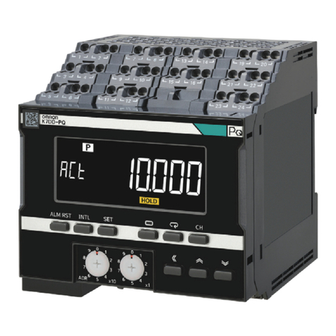
Niagara FC User manual

Model FC - Mass Flow Computer 990272 Rev. A 05/04/12
Model FC
Mass Flow Computer
Installation, Operation
Manual


FC Flow Computer
SAFETY INSTRUCTIONS .............................................................................................................1
1. INTRODUCTION
1.1UnitDescription............................................................................................................2
1.2Specications...............................................................................................................3
2. INSTALLATION
2.1GeneralMountingHints................................................................................................8
2.2MountingDiagrams......................................................................................................8
3. APPLICATIONS
3.1SteamMass................................................................................................................13
3.2SteamHeat................................................................................................................. 11
3.3SteamNetHeat..........................................................................................................13
3.4SteamDeltaHeat.......................................................................................................14
3.5CorrectedGasVolume...............................................................................................15
3.6GasMass...................................................................................................................16
3.7GasCombustionHeat................................................................................................17
3.8CorrectedLiquidVolume............................................................................................18
3.9LiquidMass................................................................................................................19
3.10LiquidCombustionHeat...........................................................................................20
3.11LiquidSensibleHeat.................................................................................................21
3.12LiquidDeltaHeat......................................................................................................22
3.13Steam–CondensateHeat.......................................................................................23
4. WIRING
4.1TerminalDesignations................................................................................................24
4.2TypicalWiringConnections........................................................................................25
4.2.1FlowInput...................................................................................................25
4.2.2StackedDPInput........................................................................................25
4.2.3PressureInput............................................................................................25
4.2.4TemperatureInput......................................................................................26
4.2.5Temperature2Input...................................................................................26
4.3WiringInHazardousAreas.........................................................................................29
4.3.1FlowInput...................................................................................................27
4.3.2PressureInput............................................................................................27
4.3.3TemperatureInput......................................................................................27
5. UNIT OPERATION
5.1FrontPanelOperationConceptforOperateMode.....................................................28
5.2GeneralOperation......................................................................................................29
5.3PasswordProtection...................................................................................................29
5.4RelayOperation..........................................................................................................29
5.5PulseOutput..............................................................................................................29
5.6AnalogOutputs...........................................................................................................29
5.7FunctionKeys;DisplayGrouping...............................................................................29
5.8RS-232SerialPortOperation.....................................................................................30
5.8.1PCCommunications...................................................................................30
5.8.2OperationofRS-232SerialPortwithPrinters............................................30
5.9RS-485SerialPortOperation.....................................................................................30
5.10PauseComputationsPrompt....................................................................................30
6. PROGRAMMING
6.1FrontPanelOperationConceptforProgramMode....................................................31
6.2EZSetup....................................................................................................................32
6.3DetailedMenuDescriptions........................................................................................34
6.4SystemParameters....................................................................................................35
6.5Display........................................................................................................................40
6.6SystemUnits..............................................................................................................42
6.7FluidData...................................................................................................................49
6.8FlowInput...................................................................................................................54
6.9OtherInput..................................................................................................................66
6.10PulseOutput.............................................................................................................69
6.11CurrentOutput..........................................................................................................70
6.12Relays.......................................................................................................................74
6.13Communication.........................................................................................................78
6.14NetworkCard............................................................................................................85
6.15Service&Analysis....................................................................................................86
CONTENTS

FC Flow Computer
7. PRINCIPLE OF OPERATION
7.1General.......................................................................................................................92
7.2SquareLawFlowmeterConsiderations......................................................................92
7.3FlowEquations...........................................................................................................92
7.3.1FlowInputComputation..............................................................................92
7.3.2PressureComputation................................................................................93
7.3.3TemperatureComputation..........................................................................93
7.3.4Density/ViscosityComputation...................................................................93
7.3.5CorrectedVolumeFlowComputation.........................................................94
7.3.6MassFlowComputation.............................................................................95
7.3.7CombustionHeatFlowComputation..........................................................95
7.3.8HeatFlowComputation..............................................................................96
7.3.9SensibleHeatFlowComputation...............................................................96
7.3.10LiquidDeltaHeatComputation.................................................................96
7.3.11ExpansionFactorComputationforSquareLawFlowmeters...................96
7.3.12UncompensatedFlowComputation.........................................................98
7.3.13ILVAFlowMeterEquations.......................................................................99
7.4ComputationoftheD.P.Factor................................................................................100
8. RS-232 SERIAL PORT
8.1RS-232SerialPortDescription.................................................................................101
8.2InstrumentSetupbyPCOverSerialPort................................................................101
8.3OperationofSerialCommunicationPortwithPrinters.............................................101
8.4FCRS-232PortPinout.............................................................................................101
9. RS-485 SERIAL PORT
9.1RS-485SerialPortDescription.................................................................................102
9.2General.....................................................................................................................102
9.3OperationofSerialCommunicationPortwithPC....................................................102
9.4FCRS-485PortPinout.............................................................................................102
10. FLOW COMPUTER SETUP SOFTWARE
10.1SystemRequirements............................................................................................103
10.2CableandWiringRequirements.............................................................................103
10.3InstallationforWindows™3.1or3.11.....................................................................103
10.4UsingtheFlowComputerSetupSoftware.............................................................103
10.5FileTab...................................................................................................................104
10.6SetupTab...............................................................................................................104
10.7ViewTab.................................................................................................................105
10.8Misc.Tab................................................................................................................105
11. GLOSSARY OF TERMS
10GlossaryOfTerms.....................................................................................................106
12. Diagnosis and Troubleshooting
12.1ResponseofFConErrororAlarm.........................................................................109
12.2DiagnosisFlowchartandTroubleshooting..............................................................109
12.3ErrorMessages...................................................................................................... 110
Appendix A
FluidPropertiesTable..................................................................................................... 113
Appendix B - Setup Menus
SetupMenuswithOperatorCodeAccess...................................................................... 114
SetupMenuswithSupervisorCodeAccess................................................................... 115
Appendix C - RS-485 Modbus Protocol
Description...................................................................................................................... 116
WiringPinoutandInstallation......................................................................................... 117
RegisterandCoilUsage................................................................................................. 119
CONTENTS

FC Flow Computer
1
!
SAFETY INSTRUCTIONS
The following instructions must be observed.
• Thisinstrumentwasdesignedandischeckedinaccordancewith
regulationsinforceEN60950(“Safetyofinformationtechnology
equipment,includingelectricalbusinessequipment”).
Ahazardoussituationmayoccurifthisinstrumentisnotusedfor
itsintendedpurposeorisusedincorrectly.Pleasenoteoperating
instructionsprovidedinthismanual.
• Theinstrumentmustbeinstalled,operatedandmaintainedby
personnelwhohavebeenproperlytrained.Personnelmustread
andunderstandthismanualpriortoinstallationandoperationofthe
instrument.
• Themanufacturerassumesnoliabilityfordamagecausedbyincorrect
useoftheinstrumentorformodicationsorchangesmadetothe
instrument.
Technical Improvements
• Themanufacturerreservestherighttomodifytechnicaldatawithout
priornotice.

FC Flow Computer
2
1. Introduction
PeakDemandOption
Thereareapplicationswherecustomerchargesaredetermined
inpartbythehighesthourlyaveragedowrateobservedduring
abillingperiod.
ThepeakdemandoptionfortheFCisintendedforapplica-
tionswhereitisimportanttocomputesuchanhourlyaverage
owrate,tonotethevalueofthepeakoccurrenceandthecor-
respondingtimeanddateofthatevent.
Thedemandlasthourrateiscomputedbasedonthecurrent
totalandthetotal60minutesprior.Thisvalueisrecomputed
every5minutes.
Thepeakdemandisthehighestvalueobservedinthedemand
lasthour.
Thetimeanddatestampisthetimeanddateatwhichthehigh-
estpeakdemandoccurred.
TheDemandLastHourand/orPeakDemandcanbedirectly
viewedonthedisplaybypressingtheRATEkeyandthen
scrollingthroughtherateswiththe^/varrowkeyuntilthede-
sireditemisviewed.
ThePeakTimeandDatestampcanbeviewedonthedisplay
bypressingtheTIMEandthenscrollingthroughthetimere-
latedparametersusingthe^/varrowkeysuntilthedesireditem
isviewed.
Alloftheseitemscanbeincludedintothescrollingdisplaylist
alongwiththeotherprocessvaluesandtotalizersinauser
selectablelist.
ThepeakdemandmaybeclearedbypressingtheCLEARkey
whileviewingthePEAKDEMANDorbymeansofacommand
ontheserialport.
ThePeakTimeandDatestampcanbeviewedonthedisplay
bypressingtheTIMEandthenscrollingthroughthetimere-
latedparametersusingthe^/varrowkeysuntilthedesireditem
isviewed.
TheDemandLastHourandPeakDemandcanbeassigned
tooneoftheanalogoutputs.Thedemandlasthourorpeak
demandcouldthuslybeoutputonarecordingdevicesuchas
astripchartrecorderorfedintoabuildingenergyautomation
system.
TheDemandLastHourandPeakDemandcanbeassigned
tooneoftherelays.Thecustomercanbenotiedthatheis
approachingorexceedingacontracthighlimitbyassigningthe
demandlasthourtooneoftherelaysandsettingthewarn-
ingpointintothesetpoint.Awarningmessagewouldalsobe
displayed.
Thepeakdemandmaybeusedinconjunctionwiththeprintlist
anddataloggertokeeptrackofhourlycustomerusageproles.
TheDemandLastHour,PeakDemand,andTimeandDate
Stampinformationcanbeaccessedovertheserialports.The
PeakDemandmayalsoberesetovertheserialports.
Thepeakdemandoptionmayalsobeusedasaconditionto
calloutinremotemeteringbymodem.
EZ Setup
TheunithasaspecialEZsetupfeaturewheretheuserisguided
through a minimum number of steps to rapidly congure the
instrumentfortheintendeduse.TheEZsetuppreparesaseries
ofquestionsbasedonowequation,uid,andowmetertype
desiredintheapplication.
1.1 Unit Description:
The FC Flow Computer satises the instrument requirements
foravarietyofowmetertypes inliquid,gas,steamand heat
applications. Multiple ow equations are available in a single
instrumentwithmanyadvancedfeatures.
Thealphanumericdisplayoffersmeasuredparametersineasyto
understandformat.Manualaccesstomeasurementsanddisplay
scrollingissupported.
TheversatilityoftheFlowComputerpermitsawidemeasureof
applicationswithintheinstrumentpackage.Thevarioushardware
inputsandoutputscanbe“soft”assignedtomeetavarietyof
commonapplicationneeds.Theuser“softselects”theusageof
eachinput/outputwhileconguringtheinstrument.
Theisolatedanalogoutputcanbechosentofollowthevolume
ow,correctedvolumeow,massow,heatow,temperature,
pressure,ordensitybymeansofamenuselection.Mosthardware
featuresareassignablebythismethod.
TheusercanassignthestandardRS-232SerialPortfordata
logging,ortransactionprinting,orforconnectiontoamodemfor
remotemeterreading.
APCCompatiblesoftwareprogramisavailablewhichpermitsthe
usertorapidlyredenetheinstrumentconguration.
Languagetranslationoptionfeaturesalsopermittheusertodene
hisownmessages,labels,andoperatorprompts.Thesefeatures
maybeutilizedattheOEMleveltocreativelycustomizetheunit
foranapplicationoralternatelytoprovideforforeignlanguage
translations.BothEnglishandasecondlanguageresidewithin
theunit.
NX-19option
AdvancedorderingoptionsareavailableforNaturalGascalculations
wheretheuserrequirescompensationforcompressibilityeffects.
Compensationforthesecompressibilityeffectsarerequiredat
mediumtohighpressureandareafunctionofthegasspecic
gravity,%CO2,%Nitrogen,aswellastemperatureandpressure.
ThecompressibilityalgorithmusedisthatforNX-19.
Stackeddifferentialpressuretransmitteroption
ThisoptionpermitstheuseofalowrangeandhighrangeDP
transmitteronasingleprimaryelementtoimproveowtransducer
andmeasurementaccuracy.
Peakdemandoption
Thisoptionpermitsthedeterminationofanhourlyaveragedow
rate.Demandlasthour,peakdemandandtime/datestampingfor
applicationsinvolvingpremiumbilling.
Dataloggingoption
Thisoptionprovidesdatastorageinformationin64kofbattery
backedRAM.Itemstobelogged,conditionstoinitiatethelogand
avarietyofutilitiestoclearandaccessthedataviatheRS-232
portareprovided.

FC Flow Computer
3
1.2 Specications:
Environmental
OperatingTemperature:0to+50C
StorageTemperature:-40to+85C
Humidity:0-95%Non-condensing
Materials:UL,CSA,VDEapproved
Approvals: CEApprovedLightIndustrial,UL/CSAPending
Display
Type:2linesof20characters
Types:BacklitLCDandVFDorderingoptions
CharacterSize:0.3"nominal
Userselectablelabeldescriptorsandunitsofmeasure
Keypad
KeypadType:MembraneKeypad
KeypadRating:SealedtoNema4
Numberofkeys:16
RaisedKeyEmbossing
Enclosure
EnclosureOptions:Panel,Wall,ExplosionProof
Size:SeeChapter2;Installation
Depthbehindpanel:6.5"includingmatingconnector
Type:DIN
Materials:Plastic,UL94V-0,Flameretardant
Bezel:Texturedpermattnish
EquipmentLabels:Model,safety,anduserwiring
NX-19 Compressibility Calculations
Temperature -40to240F
Pressure 0to5000psi
SpecicGravity 0.554to1.0
Mole%CO2 0to15%
Mole%Nitrogen 0to15%
Power Input
The factory equipped power options are internally fused.
Aninternallinetolineltercapacitorisprovidedforadded
transientsuppression.MOVprotectionforsurgetransientis
alsosupported
UniversalACPowerOption:
85to276Vrms,50/60Hz
Fuse:TimeDelayFuse,250V,500mA
DCPowerOption:
24VDC(16to48VDC)
Fuse:TimeDelayFuse,250V,1.5A
TransientSuppression:1000V
Flow Inputs:
Flowmeter Types Supported:
Linear:
Vortex,Turbine,PositiveDisplacement,Magnetic,
GilFlo,GilFlo16point,ILVA16Point,MassFlow
andothers
SquareLaw:
Orice,Venturi,Nozzle,V-Cone,Wedge,Averaging
Pitot,Target,Verabar,Accelabarandothers
Multi-PointLinearization:
Maybeusedwithallowmetertypes.Including:16
point,UVCanddynamiccompensation.
Analog Input:
Ranges
Voltage:0-10VDC,0-5VDC,1-5VDC
Current:4-20mA,0-20mA
BasicMeasurementResolution:16bit
UpdateRate:2updates/secminimum
Accuracy:0.02%FS
AutomaticFaultdetection: Signalover/under-range,
CurrentLoopBroken
Calibration: Operatorassisted learnmode. LearnsZero
andFullScaleofeachrange
FaultProtection:
FastTransient:1000VProtection(capacitiveclamp)
ReversePolarity:Noilleffects
Over-VoltageLimit: 5 0 V D C O v e r v o l t a g e
protection
Over-CurrentProtection: Internallycurrentlimited
protectedto24VDC
Optional:StackedDPtransmitter0-20mAor4-20mA
Pulse Inputs:
NumberofFlowInputs:one
InputImpedance:10kΩnominal
TriggerLevel:(menuselectable)
HighLevelInput
LogicOn: 2to30VDC
LogicOff: 0to.9VDC
LowLevelInput(magpickup)
Selectablesensitivity:10mVand100mV
MinimumCountSpeed:0.25Hz
MaximumCountSpeed:Selectable:0to40kHz
OvervoltageProtection:50VDC
FastTransient:Protectedto1000VDC(capacitiveclamp)
Temperature, Pressure, Density Inputs
The compensation inputs usage are menu selectable for
temperature, temperature 2, pressure, density, steam trap
monitorornotused.
Calibration:Operatorassistedlearnmode
Operation:Ratiometric
Accuracy:0.02%FS
ThermalDrift:Lessthan100ppm/C
BasicMeasurementResolution:16bit
UpdateRate:2updates/secminimum
AutomaticFaultdetection:
SignalOver-range/under-range
CurrentLoopBroken
RTDshort
RTDopen
TransientProtection:1000V(capacitiveclamp)
ReversePolarity:Noilleffects
Over-VoltageLimit(VoltageInput):50VDC
Over-CurrentLimit(Internallylimitedtoprotectinputto
24VDC)
AvailableInputRanges
(Temperature/Pressure/Density/TrapMonitor)
Current:4-20mA,0-20mA
Resistance:100OhmsDINRTD
100OhmDINRTD(DIN43-760,BS1904):
ThreeWireLeadCompensation
InternalRTDlinearizationlearnsicepointresistance
1mAExcitationcurrentwithreversepolarityprotection
TemperatureResolution:0.1°C
TemperatureAccuracy:0.5°C

FC Flow Computer
4
Datalogger (optional)
Type:BatteryBackedRAM
Size: 64k
Initiate:Key,IntervalorTimeofDay
ItemsIncluded:SelectableList
DataFormat:PrinterorCSVAccessviaRS-232command
Stored Information (ROM)
Steam Tables (saturated & superheated), General Fluid
Properties, Properties of Water, Properties of Air, Natural
Gas
User Entered Stored Information (EEPROM / Nonvolatile
RAM)
TransmitterRanges,SignalTypes
FluidProperties
(specific gravity, expansion factor, specific heat,
viscosity,
isentropicexponent,combustionheatingvalue,Zfactor,
RelativeHumidity)
UnitsSelections(English/Metric)
RS-232 Communication
Uses:Printing,Setup,Modem,Datalogging
BaudRates:300,1200,2400,9600
Parity:None,Odd,Even
DeviceID:0to99
Protocol:Proprietary,Contactfactoryformoreinformation
ChassisConnectorStyle:DB9Femaleconnector
PowerOutput: 8V(150mAmax.)providedtoModem
RS-485 Communication(optional)
Uses:NetworkCommunications
BaudRates:300,600,1200,2400,4800,9600,19200
Parity:None,Odd,Even
DeviceID:1to247
Protocol:ModBusRTU
ChassisConnectorStyle:DB9Femaleconnector(standard)
Excitation Voltage
24VDC@100mAovercurrentprotected
Relay Outputs
Therelayoutputsusageismenuassignableto(Individually
for each relay) Hi/Lo Flow Rate Alarm, Hi/Lo Temperature
Alarm,Hi/LoPressureAlarm,PulseOutput(pulseoptions),
WetSteamorGeneralpurposewarning(security).
(Peakdemandanddemandlasthouroptional)
Numberofrelays:2(3optional)
ContactStyle:FormCcontacts(FormAwith3relayoption)
ContactRatings:240V,1amp
FastTransientThreshold:2000V
Analog Outputs
Theanalogoutputusageismenuassignabletocorrespond
tothe HeatRate, UncompensatedVolume Rate,Corrected
Volume Rate, Mass Rate, Temperature, Density, or
Pressure.
(Peakdemandanddemandlasthouroptional)
NumberofOutputs:2
Type:IsolatedCurrentSourcing(sharedcommon)
IsolatedI/P/C:500V
AvailableRanges:0-20mA,4-20mA(menuselectable)
Resolution:16bit
Accuracy:0.05%FSat20DegreesC
UpdateRate:5updates/sec
TemperatureDrift:Lessthan200ppm/C
MaximumLoad:1000ohms
ComplianceEffect:Lessthan.05%Span
60Hzrejection:40dBminimum
EMI:Noeffectat10V/M
Calibration:OperatorassistedLearnMode
Averaging: UserentryofDSPAveragingconstantto
causeansmoothcontrolaction
Isolated Pulse output
TheisolatedpulseoutputismenuassignabletoUncompensated
VolumeTotal,CompensatedVolumeTotal,HeatTotalorMass
Total.
IsolationI/O/P:500V
PulseOutputForm(menuselectable):OpenCollectorNPNor
24VDCvoltagepulse
NominalOnVoltage:24VDC
MaximumSinkCurrent:25mA
MaximumSourceCurrent:25mA
MaximumOffVoltage:30VDC
SaturationVoltage:0.4VDC
PulseDuration:Userselectable
Pulseoutputbuffer:8bit
Real Time Clock
TheFlowComputerisequippedwitheitherasupercapora
batterybackedrealtimeclockwithdisplayoftimeanddate.
Format:
24hourformatfortime
Day,Month,Yearformatfordate
DaylightSavingsTime(optional)
Measurement
The Flow Computer can be thought of as making a series
ofmeasurementsofow,temperature/densityandpressure
sensors and then performing calculations to arrive at a
result(s)whichisthenupdatedperiodicallyonthedisplay.The
analogoutputs,thepulseoutput,andthealarmrelaysarealso
updated.Thecyclethenrepeatsitself.
Step1: Updatethemeasurementsofinputsignals-
Raw Input Measurements are made at each input using
equationsbasedoninputsignaltypeselected.Thesystem
notesthe“outofrange”inputsignalasanalarmcondition.
Step2: ComputetheFlowingFluidParameters-
Thetemperature,pressure, viscosityanddensity equations
arecomputedasneededbasedontheowequationandinput
usageselectedbytheuser.

FC Flow Computer
5
Step3:ComputetheVolumetricFlow-
Volumetricowisthetermgiventotheowinvolumeunits.
The value is computed based on the owmeter input type
selected and augmented by any performance enhancing
linearizationthathasbeenspeciedbytheuser.
Step4:ComputetheCorrectedVolumeFlowatReference
Conditions-
Inthecaseofacorrectedliquidorgasvolumeowcalculation,
the corrected volume ow is computed as required by the
selectedcompensationequation.
Step5:ComputetheMassFlow-
Allrequiredinformationisnowavailabletocomputethemass
owrateasvolumeowtimesdensity.Aheatowcomputation
isalsomadeifrequired.
Step6:CheckFlowAlarms-
The ow alarm functions have been assigned to one of
the above ow rates during the setup of the instrument.A
comparisonisnowmadebycomparingthecurrentowrates
againstthespeciedhiandlowlimits.
Step7:ComputetheAnalogOutput-
Thisdesignatedowratevalueisnowusedtocomputethe
analogoutput.
Step8:ComputetheFlowTotalsbySummation-
A ow total increment is computed for each ow rate. This
incrementiscomputedbymultiplyingtherespectiveowrate
byatimebasescalerandthensumming.Thetotalizerformat
alsoincludesprovisionsfortotalrollover.
Step9:PulseOutputService-
Thepulseoutputisnextupdatedbyscalingthetotalincrement
whichhasjustbeendeterminedbythepulseoutputscalerand
summingittoanyresidualpulseoutputamount.
Step10:UpdateDisplayandPrinterOutput-
Theinstrumentnallyrunsatasktoupdatethevarioustable
entries associated with the front panel display and serial
outputs.
Instrument Setup
Thesetupispasswordprotectedbymeansofanumericlock
outcodeestablishedbytheuser.Thehelplineandunitsof
measurepromptsassureeasyentryofparameters.
An EZ Setup function is supported to rapidly congure the
instrument for rst time use. A software program is also
available which runs on a PC using a RS-232 Serial for
connectiontotheFlowComputer.Illustrativeexamplesmay
bedownloadedinthismanner.
The standard setup menu has numerous subgrouping of
parameters needed for ow calculations. There is a well
conceived hierarchy to the setup parameter list. Selections
made at the beginning of the setup automatically affect
offeringsfurtherdowninthelists,minimizingthenumberof
questionsaskedoftheuser.
In the setup menu, the ow computer activates the correct
setup variables based on the instrument conguration, the
ow equation, and the hardware selections made for the
compensation transmitter type, the ow transmitter type,
andmeterenhancements(linearization)optionsselected.All
requiredsetupparametersareenabled.Allsetupparameters
notrequiredaresuppressed.
Alsonotethatinthemenuareparameterselectionswhichhave
preassignedindustrystandardvalues.Theunitwillassume
thesevaluesunlesstheyaremodiedbytheuser.
Mostoftheprocessinputvariableshaveavailablea“default”
oremergency valuewhich mustbe entered.Theseare the
valuesthattheunitassumeswhenamalfunctionisdetermined
tohaveoccurredonthecorrespondinginput.
It is possible to enter in a nominal constant value for
temperature or density, or pressure inputs by placing the
desirednominal value intothe default valuesand selecting
"manual".Thisisalsoaconveniencewhenperformingbench
toptestswithoutsimulators.
Thesystemalsoprovidesaminimumimplementationofan
“audittrail”whichtrackssignicantsetupchangestotheunit.
This feature is increasingly being found of benet to users
or simply required by Weights and Measurement Ofcials
in systems used in commerce, trade, or “custody transfer”
applications.
Simulation and Self Checking:
Thismodeprovidesanumberofspecializedutilitiesrequired
forfactory calibration,instrumentcheckoutonstart-up, and
periodiccalibrationdocumentation.
A service password is required to gain access to this
specializedmodeof operation.Normallyquality, calibration,
andmaintenancepersonnelwillndthismodeofoperation
veryuseful.
Manyofthese tests maybe used duringstart-upof a new
system.Outputsignalsmaybeexercisedtoverifytheelectrical
interconnectsbeforetheentiresystemisputonline.
ThefollowingactionitemsmaybeperformedintheDiagnostic
Mode:
PrintCalibration/MaintenanceReport
ViewSignalInput(Voltage,Current,Resistance,Frequency)
ExamineAuditTrail
PerformaSelfTest
PerformaServiceTest
ViewErrorHistory
PerformPulseOutputCheckout/Simulation
PerformRelayOutputCheckout/Simulation
PerformAnalogOutputCheckout/Simulation
CalibrateAnalogInputsusingtheLearnFeature
CalibrateAnalogOutputusingtheLearnFeature
ScheduleNextMaintenanceDate
Notethatacalibrationoftheanaloginput/outputwilladvance
the audit trail counters since it effects the accuracy of the
system.

FC Flow Computer
6
Operation of Steam Trap Monitor
In applications on Saturated Steam, the otherwise unused
CompensationInputmaybeconnectedtoasteamtrapmonitor
thatoffersthefollowingcompatibleoutputsignallevels:
4mA=trapcold
12mA=trapwarmandopen(blowing)
20mA=trapwarmandclosed
Innormaloperationasteamtrapiswarmandperiodicallyopens
andclosesinresponsetotheaccumulationofcondensate.A
coldtrapisindicationthatitisnotpurgingthecondensate,a
trapthatisconstantlyblowingisanindicationthatitisstuck
open. To avoid a false alarm, the FC permits the user to
programadelay,ortimeperiod,whichshouldbeconsidered
normalforthetraptobeeithercold,oropen.Analarmwill
onlybeactivatedifthetrapisdetectedascontinuouslybeing
intheabnormalstatesforatimeperiodgreaterthanthisTRAP
ERRORDELAYtime.
The user selects to use the Compensation Input for Trap
Monitoringbyselecting“4-20mATRAPSTATUSastheINPUT
SIGNALforOTHERINPUT1.
Theusercan programtheERROR DELAYtime in HH:MM
formatintoboththeTRAPERRORDELAY(coldtraperror)
menu and the TRAP BLOWING DELAY (trap stuck open)
menu.
The FC will warn the operator of a TRAP ERROR when
an abnormal condition is detected. The error can be
acknowledged by pressing the ENTER key. However, the
problem may reassert itself if there is a continued problem
withthesteamtrap.
Inaddition,theeventisnotedintheERRORLOG.
Itisalsopossiblefortheusertoprogramatrapmalfunction
asoneoftheconditionsworthyofaCALLOUTofaproblem
byselectingthiserrorintheERRORMASK.
TheData-LoggingoptionoftheFCcanalsobeusedtologthe
performanceofthetrapbystoringthe%oftimethetraphas
beencold,and/orblowingopenduringthedataloginterval.
Datalogging Option
The Datalogging Option for the FC permits the user to
automaticallystoresetsofdataitemsasarecordonaperiodic
basis.Adatalogrecordmaybestoredastheresultofeithera
PRINTkeydepression,oranINTERVAL,oraTIMEOFDAY
requestforadatalog.
Theuserdenesthelistofitemstobeincludedineachdatalog
byselectingtheseinthePRINTLISTmenulocatedwithinthe
COMMUNICATIONSSUBMENU.
Theuserselectswhatwilltriggeradatalogrecordbeingstored
inthePRINTINITIATEmenu.ThechoicesarePRINTKEY,
INTERVAL,andTIMEOFDAY.
The user can select the datalog store interval in a HH:MM
formatinthePRINTINTERVALmenu.
Theusercanalsoselectthestoretimeofdayina24hrHH:
MMformatinthePRINTTIMEmenu.
Theusercanalsodenewhetherhejustwantsthedatastored
intothedatalogger,orifhewantsthedatabothstoredinthe
dataloggerandsentoutovertheRS232portintheDATALOG
ONLYmenu.
Theusercandenetheformathewishesthedatatobeoutput
inusingtheDATALOGFORMATmenu.ChoicesarePRINTER
andDATABASE.PRINTERformatwilloutputthedatarecords
inaformsuitabletodumptoaprinter.DATABASEformatwill
outputthevaluesinaCSV,orCommaSeparatedVariablewith
Carriagereturndelimitingofeachrecord.
Anumberofserialcommandsarealsoincludedtoaccessand
manipulateinformationstoredwithinthedatalogger.Among
theseRS232commandcapabilitiesarethefollowingactions:
ClearDataLogger
SendallDatainDatalogger
SendOnlyNewDatasinceDataloggerwaslastRead
SendDataforthedateincludedintherequest
SendthecolumnheadingtextfortheCSVdataelds
SendthecolumnunitsofmeasuretextfortheCSVdata
elds
Storeonenewrecordintodataloggernow
ReadNumberofNewRecordsinthedatalogger
Readnumberofrecordscurrentlyinthedatalogger
Read the maximum number of records capacity of the
datalogger
MovePointerBackNrecords
DumpRecordatPointer
Dumprecordsnewerthanpointer
DumpdatafromNrecordsback
ThedataloggeroptionisusedinconjunctionwiththeRS-232
portinremotemeteringapplications.
The technical details associated with the serial commands
arelistedinUniversalSerialProtocolManualavailableupon
request.
RS-232 Serial Port
TheFlowComputerhasa generalpurposeRS-232Port
whichmaybeusedforanyoneofthefollowingpurposes:
TransactionPrinting
DataLogging
RemoteMeteringbyModem
ComputerCommunicationLink
CongurationbyComputer
PrintSystemSetup
PrintCalibration/MalfunctionHistory
Instrument Setup by PC’s over Serial Port
ADisketteprogramisprovidedwiththeFlowComputerthat
enablestheusertorapidlyconguretheFlowComputer
usinganPersonnelComputer.Includedonthedisketteare
commoninstrumentapplicationswhichmaybeusedasa
startingpointforyourapplication.Thispermitstheuserto
haveanexcellentstartingpointandhelpsspeedtheuser
throughtheinstrumentsetup.

FC Flow Computer
7
Operation of Serial Communication Port with Printers
TheFlowComputer’sRS-232channelsupportsanumber
of operating modes. One of these modes is intended to
support operation with a printer in metering applications
requiringtransactionprinting,dataloggingand/orprinting
ofcalibrationandmaintenancereports.
Fortransactionprinting,the userdenestheitemsto be
includedintheprinteddocument.Theusercanalsoselect
whatinitiatesthetransactionprintgeneratedaspartofthe
setupoftheinstrument.Thetransactiondocumentmaybe
initiatedviaafrontpanelkeydepression.
Indatalogging,theuserdenestheitemstobeincludedin
eachdatalogasaprintlist.Theusercanalsoselectwhen
orhowoftenhewishesadatalogtobemade.Thisisdone
duringthesetupoftheinstrumentaseitheratimeofdayor
asatimeintervalbetweenlogging.
The system setup and maintenance report list all the
instrument setup parameters and usage for the current
instrument configuration. In addition, the Audit trail
informationispresentedaswellasastatusreportlistingany
observedmalfunctionswhichhavenotbeencorrected.
Theuserinitiatestheprintingofthisreportatadesignated
point in the menu by pressing the print key on the front
panel.
Operating Serial Communication Port with Modems
TheFCoffersanumberofcapabilitiesthatfacilitateitsuse
withmodems.TheFC’sRS232portcanbeconnectedto
amodeminordertoimplementaremotemeteringsystem
that uses either the phone companies standard phone
linesorcellulartelephone system.Inadditionto remote
meter readings, the serial commands may also be used
toexamineand/ormakesetupchangestotheunit,andto
checkforproperoperationorinvestigateproblems.Several
hundredcommandsaresupported.Acompatibleindustrial
modemaccessoryandinterconnectingcablingisofferedin
theMPP2400NspecicallydesignedforusewiththeFC.
TheFCandModemcanbeusedtogethertocreatesystems
withoneormoreofthefollowingcapabilities:
1. PolltheFCunitforinformationfromaremotePC.
2. CallOutfromtheFCunittoaremotePConascheduled
readingtimeand/orcrisisbasis
3. Somecombinationoftheabovetwodescriptionswhere
theunitispolledbyonePCandcallsintotoadifferent
PCifaproblemisdetected.
Infact,uptoveFCunitscansharethesamemodem.Each
FCmusthaveauniqueDEVICEID.Thismultidroppingof
owcomputersonasinglemodemispopularwhenthere
areseveralowcomputersmountedneareachother.
In most applications using modem communications, the
FC’sRS232USAGEisrstsetequaltoMODEM.EachFC
onasharedmodemcableisgivenauniqueserialdevice
addressorDEVICEID.TheBAUDRATEiscommonlyset
to2400,thePARITYsettoNONE,andtheHANSHAKING
settoNONEtocompletethebasicsetup.TheremotePC’s
communicationsettingsarechosentomatchthese.
The level of complexity of the Supetrol-2 to Modem
connectioncanrangefromsimpletomorecomplex.
InasimplesystemaremotePCwillcallintothetelephone
numberofthe modem.The modemwillanswer the call,
andestablishaconnectionbetweentheFCandtheremote
PC.Anexchangeofinformationcannowoccur.TheFCwill
actasaslaveandrespondtocommandsandrequestsfor
informationfromtheremoteMASTERPC.TheMASTER
PCwillendtheexchangebyhandingup.
However,it ismorecommon thattheFCwillbeusedto
control the modem. In these applications the following
communicationmenusettingswouldbeused:
RS232USAGE=MODEM
DEVICE ID, BAUD RATE, PARITY, and
HANDSHAKINGareset
MODEMCONTROL=YES
DEVICE MASTER = YES (When multidropping
several FC's, only one unit will be the DEVICE
MASTER)
MODEMAUTOANSWER=YES(Thisinstructsthe
unittoanswerincomingcalls)
HANGUPIFINACTIVE=YES(Thisinstructstheunit
tohangupthelineifnoactivitiesoccurwithinseveral
minutes).
A more complex form of a remote metering system can
beimplementedwheretheFCwillinitiateacalltocontact
theremotePCatascheduledtimeand/orintheeventofa
problemthathasbeendetected.Intheseapplicationsthe
FChasadditionalsetupcapabilitiesincluding:
TheFCmusthaveauniqueidentierassignedtoit
(usingtheTAGNUMBER)
CallOutTelephonenumbermustbeenteredinthe
CALLOUTNUMBER
Thescheduledcallouttimeforthedailyreadingmust
beenteredinCALLOUTTIME
Adecisionmustbemadewhethertheunitwillbeused
tocallonerror(s)inCALLONERROR
Theparticularerrorconditionstocalloutonmustbe
denedintheERRORMASK
TheNUMBEROFREDIALStobeattemptediflineis
busymustbeenteredinthatcell
HANGUPIFINACTIVE=YESwilldisconnectthecall
ifremotecomputerdoesnotrespond.
ConsulttheUniversalSerialCommandsUserManualfor
detailsontheindividualcommandssupportedbytheFC.
ContacttheFlowApplicationsGroupforadiscussiononthe
remotemeteringsystemcapabilitiesyouareconsidering.
NOTE: Some modems can be congured in advance to
answer incoming calls, terminate phone connections if
communicationsislost.Insuchapplicationstheremaybe
noneedfortheFCtobefunctioningto“control”themodem.
SettingtheRS233USAGE=COMPUTERwilllikelywork.
RS-485 Serial Port (optional)
The RS-485 serial port can be used for accessing ow
rate,total,pressure,temperature,densityandalarmstatus
information.Theportcanalsobeusedforchangingpresets
andacknowledgingalarms.

FC Flow Computer
8
2. Installation
2.1 General Mounting Hints:
TheFCFlowComputershouldbelocatedinanareawithaclean,dryatmosphere
whichisrelativelyfreeofshockandvibration.Theunitisinstalledina5.43"(138mm)
wideby2.68"(68mm)highpanelcutout.(seeMountingDimensions)Tomountthe
FlowComputer,proceedasfollows:
a.Preparethepanelopening.
b.Slidetheunitthroughthepanelcutoutuntiltheittouchesthepanel.
c.Installthescrews(provided)inthemountingbracketandslipthebracketoverthe
rearofthecaseuntilitsnapsinplace.
d.Tightenthescrewsrmlytoattachthebezeltothepanel.3in.lb.oftorquemust
beappliedandthebezelmustbeparalleltothepanel.
NOTE: TosealtoNEMA4X/IP65specications,suppliedbezelkitmustbeused
andpanelcannotexmorethan.010".
Whentheoptionalbezelkitisused,thebezeladaptormustbesealedto
thecaseusinganRTVtypesealertomaintainNEMA4X/IP65rating.
General Mounting Hints
Mounting Procedure
NEMA4X / IP65 Specications
FC FC
BezelAdaptor
Gasket
MountingBracket
MountingBracket
Standard Mounting Bezel Kit Mounting
Dimensions
Dotted Line Shows Optional Bezel Kit
Panel
Cutout
5.43
(138)
2.68
(68)
Dimensions are in inches (mm)
5.67 (144)
2.83
(72)
3.43
(87)
6.18
6.15
(156) 0.5
(13)
0.28 (7.2)
0.4 (10)
2.2 Mounting Diagrams:

FC Flow Computer
9
1.10
(28)
1.10
(28)
7.8 (198)
4.72 (120)
0.59
(15)
0.75” Conduit Knockouts
(5 places)
1.06
(27)
9.4 (238)
7.3 (184)
2.34 (59.5)
8.4 (213.4)
4.13 (105)
2.33 (59)
0.385
(9.8)
Security Tag
Provisions
0.625”ø 0.75”ø 5 places
1.10
(28)
1.10
(28)
1.10
(28)
1.10
(28)
1.10
(28)
1.10
(28)
Wall Mount (mountingoptionW)
2.2 Mounting Diagrams:
(continued)
NEMA4 Wall Mount (mountingoptionN)

FC Flow Computer
10
Explosion Proof Mount (mountingoptionX)
2.2 Mounting Diagrams:
(continued)
Explosion Proof Mount (mountingoptionE)
9.31
(236.5)
12.06
(306.3)
3.81
(96.8)
6.56
(166.6)
.28 ±.02
(7.1 ±.5)
1.31
(33.3)
8.88
(225.5)
3.5
(88.9)
10.19
(258.8)
2.5
(63.5)
2.5
(63.5)
5.09
(129)
3.0
(76.2)
1/4" - 20UNC-2B
TAP x 5/16" DEEP
(6) HOLES CENTERED
ON THREE SIDES FOR
MOUNTING
1/2"- 14 NPT PLUGS
(2 PLACES)
10.6
(269.2)
1/4" - 20UNC-2B
TAP x 5/16" DEEP
(6) HOLES CENTERED
ON THREE SIDES FOR
MOUNTING
3.5
(88.9)
3
(76.2)
2.13
(54)
1.75
(44.5)
5.1
(129.5)
.25
(6.35)
.5
(12.7)
4.63
(117.5)
10.19
(258.8)
3.13
(79.4)
3.13
(79.4)
3
(76.2)
.5
(12.7)

FC Flow Computer
11
3.1 Steam Mass
Measurements:
Aowmetermeasurestheactualvolumeowinasteamline.Atemperatureand/or
pressuresensorisinstalledtomeasuretemperatureand/orpressure.
Calculations:
• Density and mass ow are calculated using the steam tables stored in the ow
computer.
• With square law device measurement the actual volume is calculated from the
differentialpressure,takingintoaccounttemperatureandpressurecompensation.
• Saturatedsteamrequireseitherapressureortemperaturemeasurementwiththeother
variablecalculatedusingthesaturatedsteamcurve.
• OptionalsteamtrapmonitoringusingCompensationInput1.
Input Variables:
Superheated Steam: Flow,temperatureandpressure
Saturated Steam: Flow,temperatureorpressure
Output Results:
• DisplayResults
MassorVolumeFlowRate,ResettableTotal,Non-ResettableTotal,Temperature,
Pressure,Density(optional:peakdemand,demandlasthour,time/datestamp)
• AnalogOutput
Mass or Volume Flow Rate, Temperature, Pressure Density, Peak Demand,
DemandLastHour
• PulseOutput
MassorVolumeTotal
• RelayOutputs
Mass or Volume Flow Rate , Total, Pressure, Temperature, Alarms, Peak
Demand,DemandLastHour
Applications:
Monitoring mass ow and total of steam. Flow alarms are provided via relays and
dataloggingisavailableviaanalog(4-20mA)andserialoutputs.
STEAM MASS
Steam Mass
Illustration
3. Applications
FlowmeterTemperature
Transmitter
PRINT
5
0–
TIME
CLEAR
•
MENU
ENTER
HELP
TEMP
4
PRE 1
3
RATE
2
TOTAL
1
GRAND
6
SCROLL
7
PRE 2
8
DENS
9
Pressure
Transmitter
Mass Flow
MassFlow=volumeow•density(T,p)
Calculations
*
* or Steam Trap Monitor
*
* or Steam Trap Monitor

FC Flow Computer
12
3.2 Steam Heat
Measurements:
Aowmetermeasurestheactualvolumeowinasteamline.Atemperatureand/or
pressuresensorisinstalledtomeasuretemperatureand/orpressure.
Calculations:
• Density,massowandheatowarecalculatedusingthesteamtablesstoredinthe
owcomputer.Theheatisdenedastheenthalpyofsteamunderactualconditions
withreferencetotheenthalpyofwateratT=0°C.
• With square law device measurement the actual volume is calculated from the
differentialpressure,takingintoaccounttemperatureandpressurecompensation.
• Saturatedsteamrequireseitherapressureortemperaturemeasurementwiththeother
variablecalculatedusingthesaturatedsteamcurve.
• Optionalsteamtrapmonitoringusingcompensationinput.
Input Variables:
Superheated Steam: Flow,temperatureandpressure
Saturated Steam: Flow,temperatureorpressure
Output Results:
• DisplayResults
Heat, Mass or Volume Flow Rate, Resettable Total, Non-Resettable Total,
Temperature, Pressure, Density (optional: peak demand, demand last hour,
time/datestamp)
• AnalogOutput
Heat, Mass or Volume Flow Rate, Temperature, Pressure, Density, Peak
Demand,DemandLastHour
• PulseOutput
Heat,MassorVolumeTotal
• RelayOutputs
Heat,MassorVolumeFlowRate,Total,Pressure,TemperatureAlarms,Peak
Demand,DemandLastHour
Applications:
Monitoringheatowandtotalheatofsteam.Flowalarmsareprovidedviarelaysand
dataloggingisavailableviaanalog(4-20mA)andserialoutputs.
STEAM HEAT
Heat Flow
HeatFlow=Volumeow•density(T,p)•Sp.Enthalpyofsteam(T,p)
Calculations
Steam Heat
Illustration
Temperature
Transmitter
PRINT
5
0–
TIME
CLEAR
•
MENU
ENTER
HELP
TEMP
4
PRE 1
3
RATE
2
TOTAL
1
GRAND
6
SCROLL
7
PRE 2
8
DENS
9
Pressure
Transmitter
Orifice Plate
with DP Transmitter
FlowmeterTemperature
Transmitter
PRINT
5
0–
TIME
CLEAR
•
MENU
ENTER
HELP
TEMP
4
PRE 1
3
RATE
2
TOTAL
1
GRAND
6
SCROLL
7
PRE 2
8
DENS
9
Pressure
Transmitter
*
* or Steam Trap Monitor
*
* or Steam Trap Monitor

FC Flow Computer
13
3.3 Steam Net Heat
Measurements:
A owmetermeasurestheactual volumeowinasteamline.Atemperatureand a
pressuresensorareinstalledtomeasuretemperatureand/orpressure.Allmeasurement
aremadeonthesteamsideofaheatexchanger.
Calculations:
• Density,massowandnetheatowarecalculatedusingthesteamtablesstoredinthe
owcomputer.Thenetheatisdenedasthedifferencebetweentheheatofthesteam
andtheheatofthecondensate.Forsimplicationitisassumedthatthecondensate
(water)hasatemperaturewhichcorrespondstothetemperatureofsaturatedsteam
atthepressuremeasuredupstreamoftheheatexchanger.
• With square law device measurement the actual volume is calculated from the
differentialpressure,takingintoaccounttemperatureandpressurecompensation.
• Saturatedsteamrequireseitherapressureortemperaturemeasurementwiththeother
variablecalculatedusingthesaturatedsteamcurve.
• Optionalsteamtrapmonitoringusingcompensationinput.
Input Variables:
Superheated Steam: Flow,temperatureandpressure
Saturated Steam: Flow,temperatureorpressure
Output Results:
• DisplayResults
Heat, Mass or Volume Flow Rate, Resettable Total, Non-Resettable Total,
Temperature, Pressure, Density, (optional: peak demand, demand last hour,
time/datestamp)
• AnalogOutput
Heat, Mass or Volume Flow Rate, Temperature, Pressure, Density, Peak
Demand,DemandLastHour
• PulseOutput
Heat,MassorVolumeTotal
• RelayOutputs
Heat,MassorVolumeFlowRate,Total,Pressure,TemperatureAlarms,Peak
Demand,DemandLastHour
Applications:
Monitoringthethermalenergywhichcanbeextractedbyaheatexchangertakinginto
account the thermal energy remaining in the returned condensate. For simplication
it is assumed that the condensate (water) has a temperature which corresponds to
the temperature of saturated steam at the pressure measured upstream of the heat
exchanger.
STEAM NET HEAT
Net Heat Flow
NetHeatFlow=Volumeow•density(T,p)•[ED(T,p)–EW(TS(p))]
ED = Specicenthalpyofsteam
Ew = Specicenthalpyofwater
TS(p) = Calculatedcondensationtemperature
(=saturatedsteamtemperatureforsupplypressure)
Calculations
Steam Net Heat
Illustration
FlowmeterTemperature
Transmitter
PRINT
5
0–
TIME
CLEAR
•
MENU
ENTER
HELP
TEMP
4
PRE 1
3
RATE
2
TOTAL
1
GRAND
6
SCROLL
7
PRE 2
8
DENS
9
Pressure
Transmitter
Water
Steam
*
* or Steam Trap Monitor

FC Flow Computer
14
3.4 Steam Delta Heat
Measurements:
Measuresactualvolumeowandpressureofthesaturatedsteaminthesupplypiping
as well as the temperature of the condensate in the downstream piping of a heat
exchanger.
Calculations:
• Calculatesdensity,massowaswellasthedeltaheatbetweenthesaturatedsteam
(supply)andcondensation(return)usingphysicalcharacteristictablesofsteamand
waterstoredintheowcomputer.
• With square law device measurement the actual volume is calculated from the
differentialpressure,takingintoaccounttemperatureandpressurecompensation.
• Thesaturatedsteamtemperatureinthesupplylineiscalculatedfromthepressure
measuredthere.
Input Variables:
Supply: Flowandpressure(saturatedsteam)
Return: Temperature(condensate)
Output Results:
• DisplayResults
Heat, Mass or Volume Flow Rate, Resettable Total, Non-Resettable Total,
Temperature, Pressure, Density (optional: peak demand, demand last hour,
time/datestamp)
• AnalogOutput
Heat, Mass or Volume Flow Rate, Temperature, Pressure, Density, Peak
Demand,DemandLastHour
• PulseOutput
Heat,MassorVolumeTotal
• RelayOutputs
Heat,MassorVolumeFlowRate,Total,Pressure,TemperatureAlarms,Peak
Demand,DemandLastHour
Applications:
Calculatethesaturatedsteammassowandtheheatextractedbyaheatexchanger
takingintoaccountthethermalenergyremaininginthecondensate.
STEAM DELTA HEAT
Delta Heat Flow
NetHeatFlow=Volumeow•density(p)•[ED(p)–EW(T)]
ED = Specicenthalpyofsteam
Ew = Specicenthalpyofwater
Note:Assumesaclosedsystem.
Calculations
Steam Delta Heat
Illustration
Pressure
Transmitter Flowmeter
Temperature
Transmitter
PRINT
5
0–
TIME
CLEAR
•
MENU
ENTER
HELP
TEMP
4
PRE 1
3
RATE
2
TOTAL
1
GRAND
6
SCROLL
7
PRE 2
8
DENS
9
Water
Saturated
Steam

FC Flow Computer
15
3.5 Corrected Gas Volume
Measurements:
Aowmetermeasurestheactualvolumeowinagasline.Temperatureandpressure
sensorsareinstalledtocorrectforgasexpansioneffects.
Calculations:
• CorrectedVolumeiscalculatedusingtheow,temperatureandpressureinputsaswell
asthegascharacteristicsstoredintheowcomputer(see"FLUIDDATA"submenu).
Usethe"OTHERINPUT"submenutodenereferencetemperatureandreference
pressurevaluesforstandardconditions.
Output Results:
• DisplayResults
CorrectedVolumeorActualVolumeFlowRate,ResettableTotal,Non-Resettable
Total,Temperature,Pressure,Density(optional:peakdemand,demandlasthour,
time/datestamp)
• AnalogOutput
CorrectedVolumeorActualVolumeFlowRate,Temperature,Pressure,Density,
PeakDemand,DemandLastHour
• PulseOutput
CorrectedVolumeorActualVolumeTotal
• RelayOutputs
CorrectedVolumeorActualVolumeFlowRate,Total,pressure,Temperature
Alarms,PeakDemand,DemandLastHour
Applications:
Monitoringcorrectedvolumeowandtotalofanygas.Flowalarmsareprovidedviarelays
anddataloggingisavailableviaanalog(4-20mA)andserialoutputs.
CORRECTED
GAS VOLUME
Volume Flow
Pulse Input; Average K-Factor
inputfrequency•timescalefactor
VolumeFlow=
K-Factor
Analog Input; Linear
VolumeFlow=%input•FullScaleFlow
Corrected Volume Flow
P TrefZ
ref
CorrectedVolumeFlow=VolumeFlow• • •
P
ref T Z
Calculations
Corrected
Gas Volume
Illustration
FlowmeterTemperature
Transmitter
PRINT
5
0–
TIME
CLEAR
•
MENU
ENTER
HELP
TEMP
4
PRE 1
3
RATE
2
TOTAL
1
GRAND
6
SCROLL
7
PRE 2
8
DENS
9
Pressure
Transmitter

FC Flow Computer
16
Temperature
Transmitter
PRINT
5
0–
TIME
CLEAR
•
MENU
ENTER
HELP
TEMP
4
PRE 1
3
RATE
2
TOTAL
1
GRAND
6
SCROLL
7
PRE 2
8
DENS
9
Pressure
Transmitter
Orifice Plate
with DP Transmitter
FlowmeterTemperature
Transmitter
PRINT
5
0–
TIME
CLEAR
•
MENU
ENTER
HELP
TEMP
4
PRE 1
3
RATE
2
TOTAL
1
GRAND
6
SCROLL
7
PRE 2
8
DENS
9
Pressure
Transmitter
3.6 Gas Mass
Measurements:
Aowmetermeasurestheactualvolumeowinagasline.Temperatureandpressure
sensorsareinstalledtomeasuretemperatureandpressure.
Calculations:
• Density and mass ow are calculated using gas characteristics stored in the ow
computer.
• With square law device measurement the actual volume is calculated from the
differentialpressure,takingintoaccounttemperatureandpressurecompensation.
Output Results:
• DisplayResults
MassorVolumeFlowRate,ResettableTotal,Non-ResettableTotal,Temperature,
Pressure,Density(optional:peakdemand,demandlasthour,time/datestamp)
• AnalogOutput
Mass or Volume Flow Rate, Temperature, Pressure, Density, Peak Demand,
DemandLastHour
• PulseOutput
MassorVolumeTotal
• RelayOutputs
MassorVolumeFlowRate,Total,Pressure,Temperature,DensityAlarms,Peak
Demand,DemandLastHour
Applications:
Monitoringmassowandtotalofgas.Flowalarmsareprovidedviarelaysanddatalogging
isavailableviaanalog(4-20mA)andserialoutputs.
GAS MASS
Mass Flow
P TrefZ
ref
MassFlow=ActualVolumeFlow•ρref• • •
P
ref T Z
ρref = Referencedensity
Tref = Referencetemperature
Pref = Referencepressure
Zref = ReferenceZ-factor
Calculations
Gas Mass
Illustration
Table of contents
Other Niagara Measuring Instrument manuals
