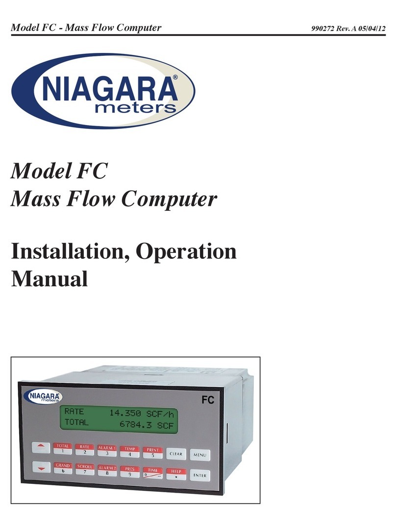
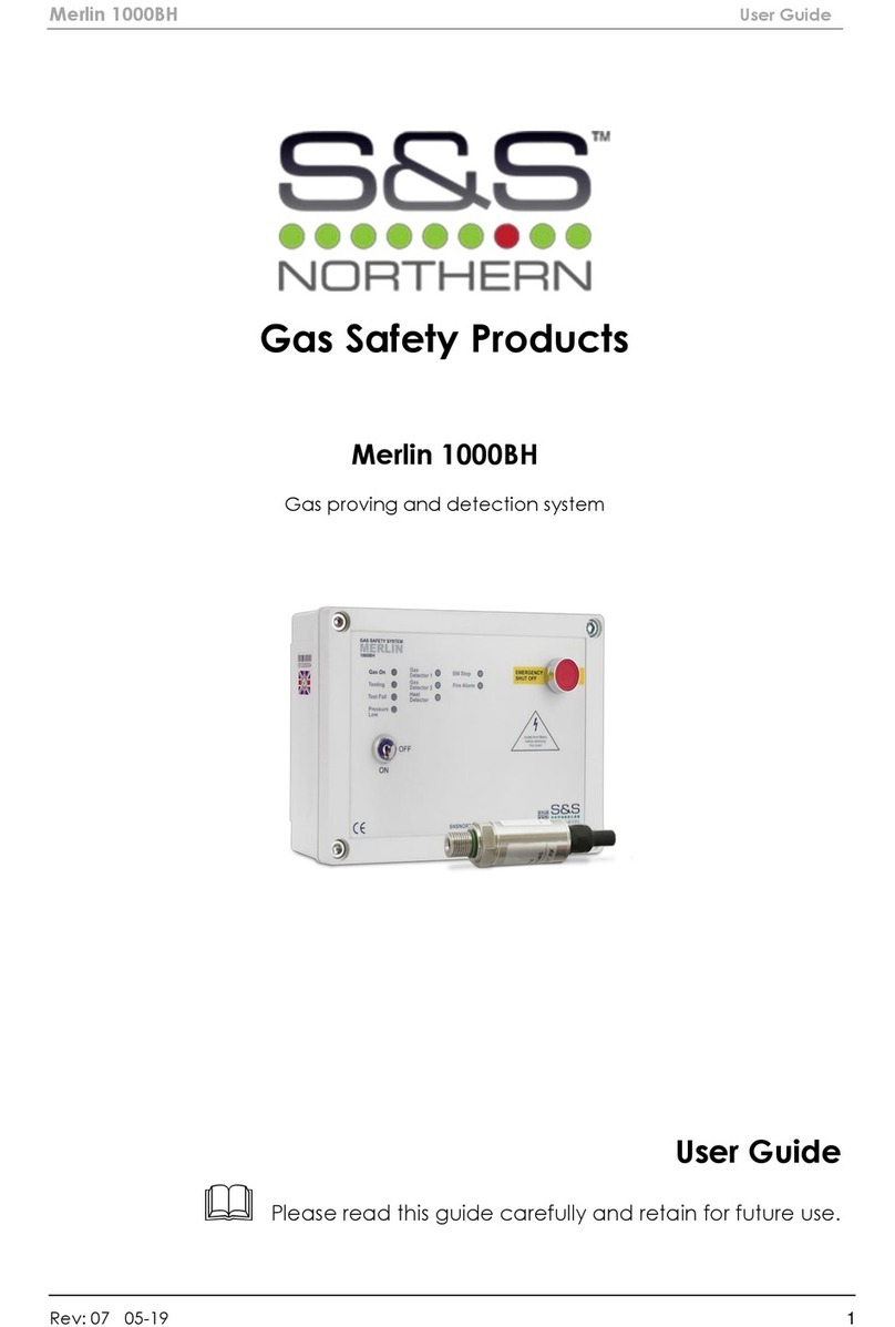
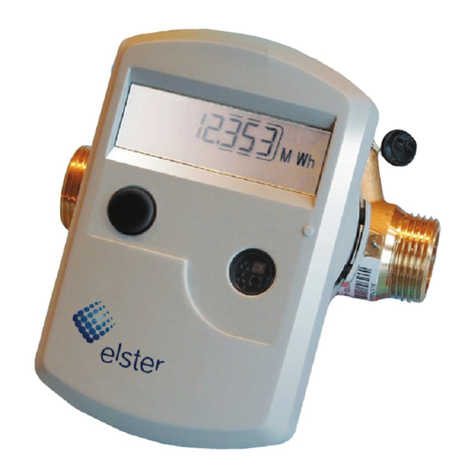
Niagara WPX Series Instruction manual

SeriesWPX
NIAGARA®
Series WPX
Models 210 and 222
Installation, Operation
& Maintenance Manual
M212
Rev.F
Model 210 – hot
Sizes 2”, 3”, and 4”
Sizes 6”, 8”, and 10”
(red)
Models 222 – cold
Sizes 2”, 3”, and 4”
Sizes 6”, 8”, and 10”
(darkgray)

SeriesWPX
Table of Contents
Model 210 – Hot Water
Installation & Operation ............................................................................... 1
General ....................................................................................................... 1
Installation ................................................................................................... 1
Operation..................................................................................................... 1
Options ........................................................................................................ 1
Model 210 Maintenance ............................................................................... 2
Register Removal ........................................................................................ 2
Removing Measuring Chamber ................................................................... 2
Installation of Measuring Chamber .............................................................. 2
Replacement Parts ...................................................................................... 3
Model 222 – Cold Water
Installation & Operation ............................................................................... 4
General ....................................................................................................... 4
Installation ................................................................................................... 4
Operation..................................................................................................... 4
Options ........................................................................................................ 4
Model 222 Maintenance ............................................................................... 5
Register Removal ........................................................................................ 5
Removing Measuring Chamber ................................................................... 5
Installation of Measuring Chamber .............................................................. 5
Replacement Parts ...................................................................................... 6
Models 210 and 222 Specifications ............................................................ 6

SeriesWPX
Model 210 – HotWater
Installation & Operation
GENERAL
The red Niagara Series WPX turbine flowmeters are ideal for the measure-
ment of water up to 250°Fin commercial and industrial applications.These
high performance meters are unsurpassed in the market place today.
INSTALLATION
The Niagara Series WPX turbine meter may be mounted in a horizontal or
vertical pipe, but never with the register on the bottom.
In order to have accurate measurement, the meter must have 5 pipe
diameters upstream and 3 pipe diameters downstream of straight uninter-
rupted pipe.
The WPX turbine must be placed in a pipeline free of scale, sediment, and
debris. If there is excessive sediment in the pipeline, protect the meter by
putting a strainer (20 mesh) upstream of the meter.
OPERATION
Air must be evacuated from the WPX turbine before operating. Slowly open
valve to let water into the meter. Gradually increase the flow rate to drive out
the air.If the meter is not filled slowly, the surge of water can damage the
measuring elements.
OPTIONS
Model 860
• Provides a high frequency pulse output for interface with Venture
Measurement instrumentation.
• Supply Voltage: 30 VDC max.
• Current Requirement: 15-20 mA.
• Output Signal: Non-symmetrical square pulse train (equal to
supply voltage).
• Wiring: Pigtail, 36”, 3-wire conductor.
• Max. Output Current: 20 mA.
Model 840
• Provides a calibrated contact closure.
• Contact Rating
Switching Voltage: 30 VDC max.
Current DC Resistive 0.2A max.
Wattage: 3 WDC max.
• Wiring: Pigtail, 36”, 22 gauge
1

SeriesWPX
Model 210 Maintenance
REGISTER REMOVAL
Model 210
Totalizer with Reed Switch and InfraredTransmitter
1. Remove strain relief nut and draw out washer and binding nut.
2.Remove screws from register cover.
3.Remove register cover.
4. Slide reed switch or infrared transmitter out of the dovetail slot in
the register.
5. Remove sealing wire out of sealing segment and working
clamp ring.
6. Pull sealing segment out of ring.
7.Turn working clamp ring and register 90 degrees to the left or the right and
lift off.
8.The register cannot be disassembled further. It is hermetically sealed and
must be replaced as a unit if damaged.
Straight Totalizer
1.Remove the fillister head screws from the register cover and lift
off cover.
2.Remove sealing wire.
3. Lift of sealing segment.
4.Turn clamp ring 90 degrees to the left or the right and lift it up with
the counter.
REMOVING MEASURING CHAMBER
Model 210 – Sizes 2”, 3”, 4”, 6”& 8”
1. Loosen sealing wire.
2. Remove hex head screws.
3. Lift out measuring chamber housing.
4. If measuring unit is stuck, loosen it by prying on the cast recesses with a
screw driver.
5. Check O-Ring for damage.Replace if necessary.
Model 210 – Size 10”
1. Loosen sealing wire.
2.Remove hex screws.
3. Grip measuring chamber housing by the two lifting eye bolts and
lift out.
4. Check O-Ring for damage and wear. Replace if necessary.
INSTALLATION OF MEASURING CHAMBER
Model 210
Install the Model 210 by following the reverse order of the removal instruc-
tions.The following items should be checked:
• O-rings and lip washers should be checked for damages before installation.
• Slightly lubricate O-rings and regulator shaft.
• The slot of regulator drive has to be in line with the regulator vane in the
starting position.
2

SeriesWPX
3
REPLACEMENT PARTS
• Measuring chamber complete
• Register assembly
Note: Part numbers are listed in the parts price book.
Model 210
1 strain relief nut
2 register cover screws
3 register cover
4 reed switch or infrared transmitter
5 sealing wire
6 sealing segment
7 working clamp ring
8 sealing wire
9 hex head screws
10 measuring chamber housing
11 o-ring

SeriesWPX
Models 222 – ColdWater
Installation & Operation
GENERAL
Theblue NiagaraSeriesWPX turbine flowmetersareideal forthe measurement
of water up to 120°F
in commercial and industrial applications.These high
performancemeters are unsurpassed in themarketplacetoday.
INSTALLATION
The Niagara Series WPX turbine meter may be mounted in a horizontal or
vertical pipe, but never with the register on the bottom.
In order to have accurate measurement, the meter must have 5 pipe
diameters upstream and 3 pipe diameters downstream of straight uninter-
rupted pipe.
The WPX turbine must be placed in a pipeline free of scale, sediment, and
debris. If there is excessive sediment in the pipeline, protect the meter by
putting a strainer (20 mesh) upstream of the meter.
OPERATION
Air must be evacuated from theWPX turbine before operating.Slowly open
valve to let water into the meter. Gradually increase the flow rate to drive out
the air.If the meter is not filled slowly, the surge of water can damage the
measuring elements.
OPTIONS
Model 573
• Provides a high frequency pulse output for interface with Venture
Measurement instrumentation.
• Supply Voltage: 24 VDC max.
• Current Requirement: 30 mA.
• Output Signal: Non-symmetrical square pulse
train (equal to supply voltage).
• Wiring: Pigtail, 36”, 3-wire conductor.
• Max. Output Current: 30 mA.
Model 840
•
Provides a calibrated contact closure.
• Contact Rating
Switching Voltage: 30 VDC max.
Current DC Resistive 0.2A max.
Wattage: 3 WDC max.
• Wiring: Pigtail, 36”, 22 gauge
4

SeriesWPX
Models 222 Maintenance
REGISTER REMOVAL
Model 222
1. Depress the tab in the register box below the hinge. Lift hinged side of
register and rotate forward to remove it from the meter.
2. Remove the sealing tape from the locking segment and register retaining
ring. Remove the locking segment from the retaining ring by prying straight
up on the locking segment with a flat screwdriver.
3. Spread the retaining ring to remove it from the slot on the top case and
remove it. Lift register off top case.
4. To re-assemble, reverse the order of the instructions above.
REMOVING MEASURING CHAMBER
Model 222 – Sizes 2”, 3”, 4”, 6”, 8”, & 10”
1. Remove the sealing wire from the case bolts. Loosen the case bolts and
removethem.
2. Lift top case and measuring chamber from the bottom casing.
3. Remove the rubber lip seal from the inlet side of the measuring chamber to
expose the 3rd screw.
4. Remove the 3 screws securing the measuring chamber to the top case.
5. To replace the measuring chamber, reverse the order of instructions above.
Note: The lip seal and casing O ring should be inspected before re-assembly.
Any worn or torn seals should be replaced.
5

SeriesWPX
Size 2” 3” 4” 6” 8” 10”
Flow Rate gpm 8-305 20-660 30-1100 45-1870 60-2860 80-4400
Pressure psi 227 227 227 227 227 227
Temperature 250°F 250°F 250°F 250°F 250°F 250°F
Accuracy ± 1% ± 1% ± 1% ± 1% ± 1% ± 1%
Registration* USG USG USG USG USG USG
Gallons per contact 10 100 100 100 100 1000
with 840 Switch or 100 or 1000 or 1000 or 1000 or 1000 or 10000
Full Scale Freq. Hz 50.8 22 36.67 31.15 47.7 14.67
with 860 Infra-Red Pulser
Pulses per Gallon* 10 2 2 1 1 .2
Models 210 (hot) Specifications
NIAGARA®
150 Venture Boulevard
Spartanburg, SC 29306
Phone: (800)778-9251, (864) 574-3327
Fax: (864) 574-8063
Internet: www.aaliant.com
M212 Rev. F 11/04
AProduct Line
REPLACEMENT PARTS
• Measuring chamber complete
• Register assembly
Note: Part numbers are listed in the parts price book.
Size 2” 3” 4” 6” 8” 10”
Flow Rate gpm 4.4-396 3.5-880 7.9-1321 17.6-1541 26.4-2862 88-5284
Pressure psi 227 227 227 227 227 227
Temperature 120°F 120°F 120°F 120°F 120°F 120°F
Accuracy ± 1% ± 1% ± 1% ± 1% ± 1% ± 1%
Registration* USG USG USG USG USG USG
Gallons per contact 10 100 100 100 100 1000
with 840 Switch or 100 or 1000 or 1000 or 1000 or 1000 or 10000
Full Scale Freq. Hz 66 14.7 22 26.7 47.7 8.8
with 573 Infra-Red Pulser
Pulses per Gallon* 10 1 1 1 1 .1
* Other units of registration available (consult factory). Hz = GPM x PPG PPG = Hz x 60
60 GPM
Wetted Material of Construction
Body: Cast Iron
Measuring Element: 120°F - Noryl
250°F - Polyethersulfone
Rotor: Polyamid
O-Ring Seals: EPDM
Models 222 (cold) Specifications
This manual suits for next models
2
Table of contents
Other Niagara Measuring Instrument manuals
