Safety information
This manual describes installation and service procedures
for implementation by specialists.
The manual must be left with the customer.
This appliance can be used by children
aged from 8 years and above and per-
sons with reduced physical, sensory or
mental capabilities or lack of experience
and knowledge if they have been given
supervision or instruction concerning use
of the appliance in a safe way and under-
stand the hazards involved. Children shall
not play with the appliance. Cleaning and
user maintenance shall not be made by
children without supervision.
This is an original manual. It may not be
translated without the approval of NIBE.
Rights to make any design or technical
modifications are reserved.
©NIBE 2023.
If the supply cable is damaged, only NIBE,
its service representative or similar author-
ised person may replace it to prevent any
danger and damage.
Symbols
Explanation of symbols that may be present in this manual.
NOTE
This symbol indicates danger to person or machine.
Caution
This symbol indicates important information about
what you should consider when installing or servi-
cing the installation.
TIP
This symbol indicates tips on how to facilitate us-
ing the product.
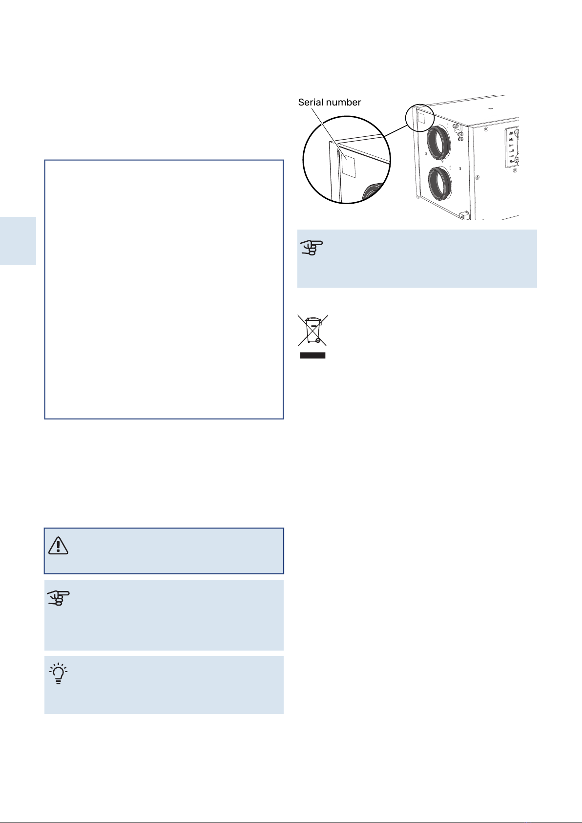
Serial number
The serial number can be found at the top, to the left of the
ventilation connection for exhaust air.
Caution
You need the product's serial number for servicing
and support.
Recovery
Leave the disposal of the packaging to the installer
who installed the product or to special waste sta-
tions.
When disposing of the product, its constituent ma-
terials and components, e.g. compressors, fans, circulation
pumps and circuit boards, must be disposed of at a special
waste station or dealer who provides this type of service.
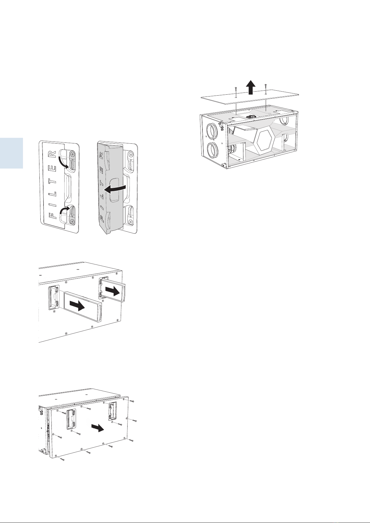
To access the separate components, refer to the section
that shows the construction of the product. No special tools
are required for access.
Improper disposal of the product by the user results in ad-
ministrative penalties in accordance with current legislation.
NIBE ERS 30-600Chapter 1 | Important information4
S
Important information