Yaesu FTDX 9000 Series User manual

FT
DX
9000D
Operation Manual


Page 1FTDX9000D OPERATION MANUAL
GENERAL DESCRIPTION
We wish to take this opportunity to thank you for your purchase of the FT DX 9000 Series Transceiver!
The FT DX 9000 is the culmination of a four-year design project. But it also is the product of our company’s fifty years of
engineering, design, and manufacturing know how. As pioneers in the development of SSB, we have led the technological
advances in Amateur Radio communications over the last half century. And now, with the introduction of the FT DX 9000
Series, we again lead the way with a no-compromise 21st-century design that will make your operating dreams come true.
More importantly, it is a radio that will let your skills and experience find expression, as you harness the excitement of HF
operating like you’ve never done before!
About This Manual. . .
The FT DX 9000 Series is a leading-edge transceiver with a number of new and exciting features, some of which may be
unfamiliar to you. In order to gain the most enjoyment and operating efficiency from your FT DX 9000, we recommend that
you read this manual in its entirety, and keep it handy for reference as you explore the many capabilities of your new
transceiver.
Before using your FT DX 9000, be sure to read and follow the instructions in the “Before You Begin” section of this manual.
Conventions Used in This Manual
Please note the conventions, described below, for operational commands and texts included in this manual.
(# )..... This refers to a switch or knob used for controlling a particular function. The name or number inside the
brackets designate the name of the switch/knob, or its reference number within this manual
.............. This is the name of a switch or knob.
[ ] .............. This indicates one of the [F1] ~ [F8] “Soft Keys” below the TFT display.
XX ........... In the texts, you may be advised to press a button momentarily, or press and hold it in for a time interval (such
as two seconds). Please be sure to observe the proper procedure when pressing a button.
OO ........... This indicates the pressing of a button when a “momentary” press is the only selection available.
Note ......................................... This is used for a note as to a particular point of interest.
Advice ..................................... This is used to amplify or expand on instructions, so as to recommend a way to gain
maximum benefit from a feature or function.
Example .................................. This is used to demonstrate an example of how a feature or function should work or be
programmed.
Quick Note /Quick Point This is used for a brief explanation of a particular aspect of operation.
Terminology ........................... An explanation of a term or expression used in this manual.
About the TFT Display
In the FT DX 9000 Series, a large 6.5” (800 x 480 dot) TFT is built into the FT DX 9000D version, and is optional on other
versions. Please see the separate TFT Operation Manual for details regarding TFT operation.
HThe TFT is a precision-designed, advanced display unit. You may observe, inside the TFT panel, a black point, or a
luminescent point or points; these are normal, and do not indicate a defective TFT. Please note.
HIf you turn on the FT DX 9000 (with the TFT) in a cold environment, or if the transceiver itself is very cold, it may
require several minutes for the TFT to warm up to full brilliance of color and full illumination. This is a normal condi-
tion, and does not indicate a breakdown.
HThere may be times when the TFT display illumination appears not to be uniform, but this is a normal condition.
This device is designed for Amateur Radio operation only. Operation on the Amateur Radio bands requires a license, in
accordance with the telecommunications statutes in your country. The discussions in this manual presume that you possess
the fundamental knowledge consistent with your status as a licensed Amateur Radio operator.

Page 2 FTDX9000D OPERATION MANUAL
TABLE OF CONTENTS
General Description ............................................. 1
About This Manual. . . ........................................................................ 1
Conventions Used in This Manual ...................................................... 1
About the TFT Display ........................................................................ 1
Before You Begin. . . ............................................ 4
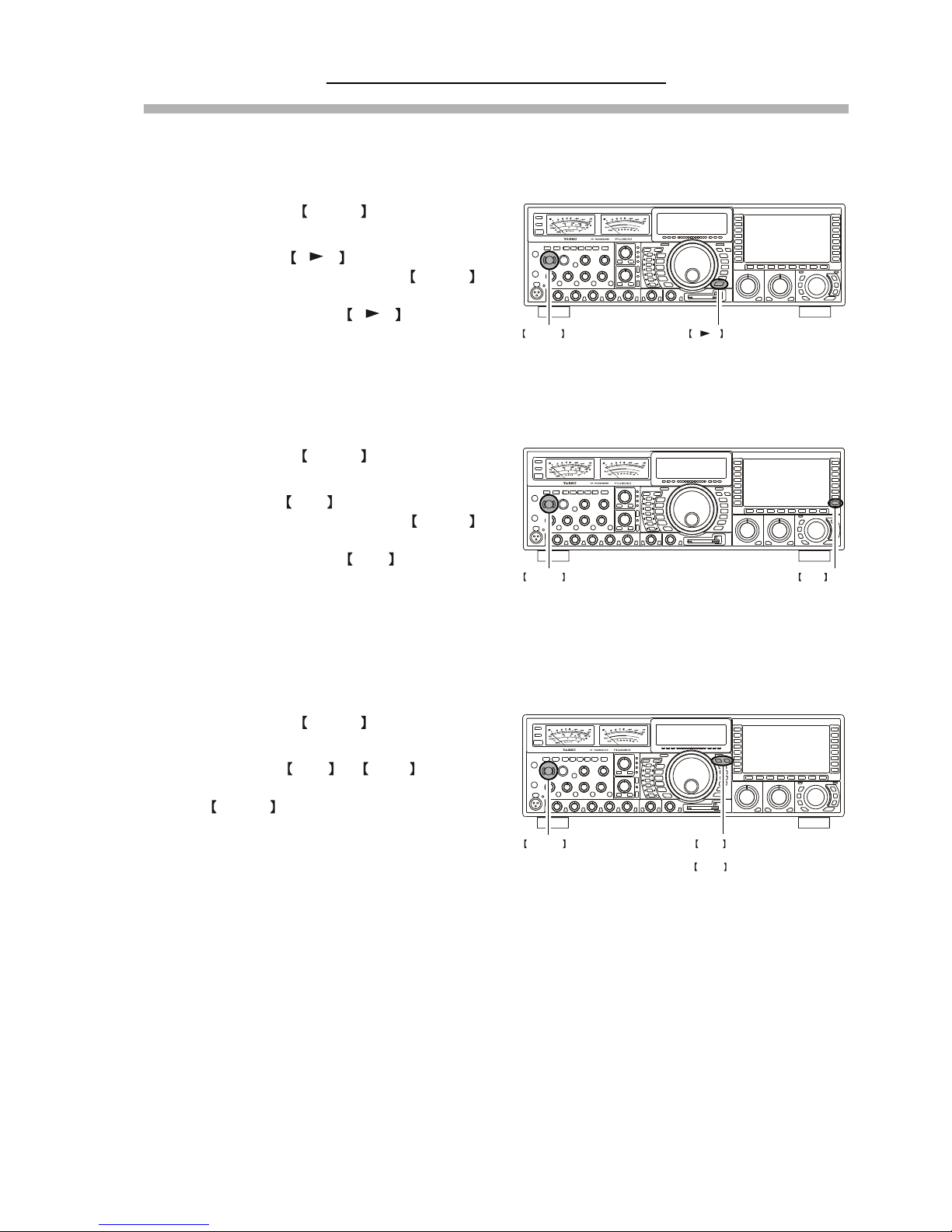
1. Connecting AC Power ..................................................................... 4
2. Setting Your Local Time ................................................................. 4
3. Configuring Your FT DX 9000 Using the Menu ............................ 4
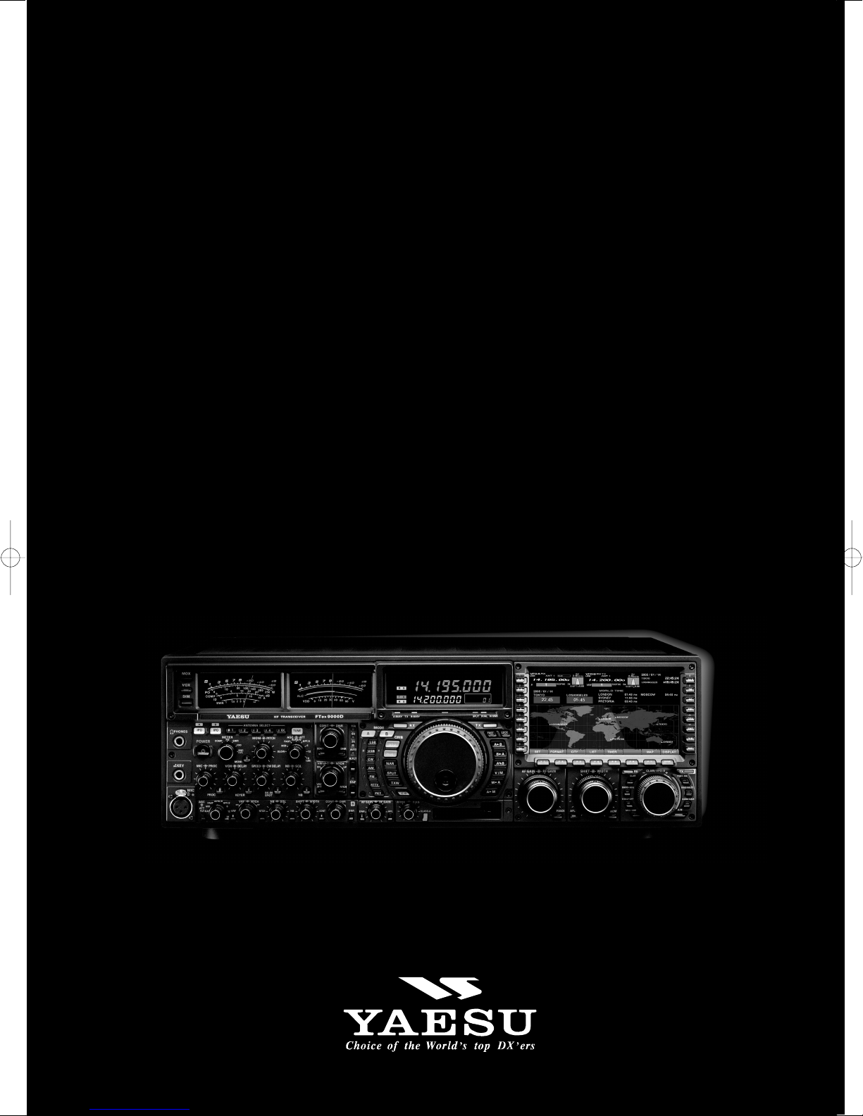
4. Connecting and Selecting the Microphone ..................................... 5
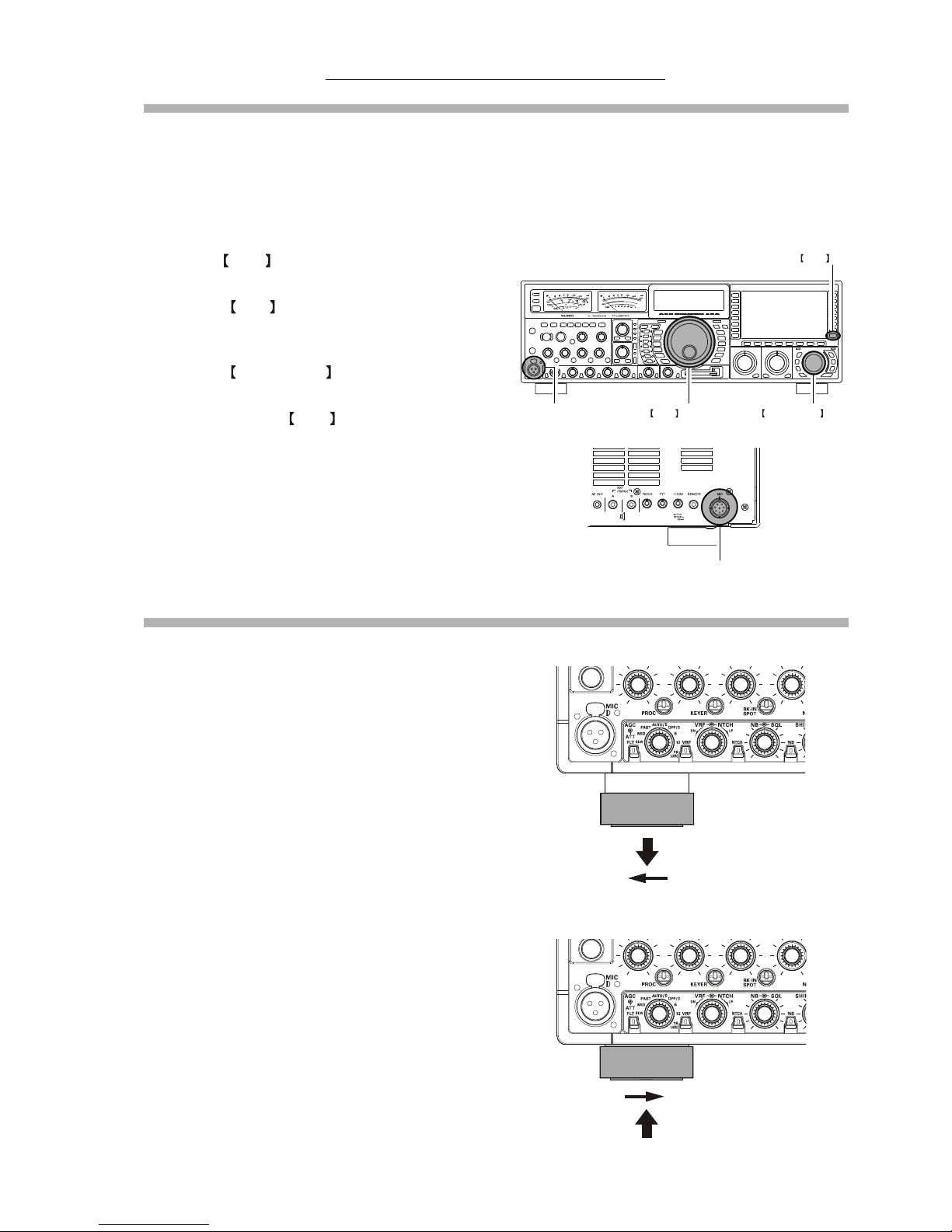
5. Extending the Front Feet ................................................................. 5
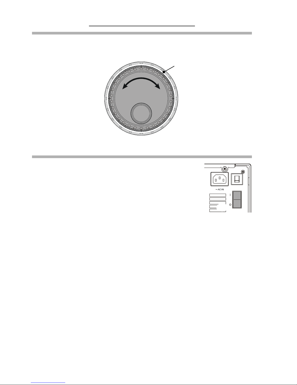
6. Adjusting the Main Dial Torque ..................................................... 6
7. Restarting Power after a Voltage Fluctuation .................................. 6
8. Resetting the Microprocessor .......................................................... 7
Resetting Memories (Only) .......................................................... 7
Menu Resetting ............................................................................ 7
Full Reset ...................................................................................... 7
Features ................................................................ 8
Accessories ........................................................ 10
Options ............................................................... 11
Installation and Interconnections..................... 12
Antenna Considerations .................................................................... 12
About Coaxial Cable ......................................................................... 12
Grounding .......................................................................................... 13
Connection of Antenna and Power Cables........................................ 14
Connection of Microphone,Headphones and
FH-2 Remote Control Keypad Connec ................... 15
Key, Keyer, and Computer-Driven Keying Interconnections ........... 16
VL-1000 Linear Amplifier Interconnections .................................... 17
Interfacing to Other Linear Amplifiers.............................................. 18
Plug/Connector Pinout Diagrams .................... 19
Front Panel Controls ......................................... 20
Rear Panel .......................................................... 36
Frequency Display ............................................. 39
TFT Feature/Control Details .............................. 40
FH-2 Operation ................................................... 41
Basic Operation:
Receiving on Amateur Bands .......... 42
Operation ........................................................................................... 43
Operation on 60-Meter (5 MHz) Band (U.S. version only) .............. 45
CLAR (Clarifier) Operation on Main (VFO-A) ................................ 46
LOCK ................................................................................................ 47
DIM ................................................................................................... 47
B-DISP OFF ...................................................................................... 47
Convenient Features ......................................... 48
Dual Receive ..................................................................................... 48
P.BACK (Audio Playback) from Main (VFO-A) Receiver .............. 52
"MY Bands" Operation ..................................................................... 53
Band Stack Operation ....................................................................... 54
Dial Swap Configuration (AF/RF GAIN controls) ........................... 55
C.S (Custom Switch) ......................................................................... 56
More Frequency Navigation Techniques .......................................... 57
ANTENNA SELECTION .................................................................. 58
Changing the Speaker Output Configuration ................................... 59
Receiver Operation (Front End Block Diagram) .............................. 60
IPO (Intercept Point Optimization) ................................................... 61
ATT .................................................................................................... 62
RF Gain (SSB/CW/AM Modes) ....................................................... 63
Advanced Interference
-Suppression Features ................... 64
Using the µ-Tune Feature .................................................................. 64
Using the VRF (Variable RF Front-end Filter) ................................. 66
Interference Rejection ....................................... 67
R.FLT (Roofing Filters) ..................................................................... 67
CONT (Contour) Control Operation ................................................. 68
IF SHIFT Operation (SSB/CW/RTTY/PKT/AM Modes) ................. 69
WIDTH (IF DSP Bandwidth) Tuning
(SSB/CW/RTTY/PKT Modes) ........................ 70
Using IF Shift and Width Together ............................................ 70
IF Notch Filter Operation (SSB/CW/RTTY/PKT/AM Modes) ........ 71
Digital Noise Reduction (DNR) Operation ....................................... 72
NARROW (NAR) One-Touch IF Filter Selection ............................ 73
Digital Notch Filter (DNF) Operation ............................................... 74
IF Noise Blanke (NB) Operation ...................................................... 74
Tools for Comfortable and
Effective Reception .................... 75
AGC (Automatic Gain Control) ........................................................ 75
SLOPED AGC Operation ........................................................... 76
Mute Feature Main (VFO-A) Band ................................................. 77
Audio Limiter (AFL) Feature ............................................................ 77
Adjacent Channel Monitor (ACM) CW Mode Only ...................... 78
SSB/AM Mode Transmission
(Let's Look at the Transmitter. . .) ........... 80
Phantom Voltage for Condenser Microphones ................................. 81
Using the Automatic Antenna Tuner ................ 82
ATU Operation .................................................................................. 82
About ATU Operation ....................................................................... 83
Lithium Battery Replacement ........................................................... 84
SSB/AM Mode Transmission ............................86
Using the Speech Processor - SSB, AM Mode - ............................ 86
Adjusting the SSB Transmitted Bandwidth ...................................... 87
Signal Quality Enhancement Using the
Parametric Microphone Equalizer ................................... 88
Low- Distortion CLASS-A Operation ............................................... 90
Voice Memory ................................................................................... 92
Convenient Transmitter Accessories ............... 94
VOX: Automatic TX/RX Switching using Voice Control
SSB/AM/FM Modes ............. 94
Using the MONITOR ........................................................................ 94
Split Operation Using the TX Clarifier (VFO-A Operation) ........... 95
Clarifier Offset Bar Indicator ..................................................... 95
Split-Frequency Operation ................................................................ 96
Quick Split Operation ................................................................ 97
Full Duplex Operation ....................................................................... 98

Page 3FTDX9000D OPERATION MANUAL
TABLE OF CONTENTS
CW Mode Operation ........................................ 100
Setup for Straight Key (and Straight Key emulation) Operation .... 100
Using the Built-in Electronic Keyer ................................................ 101
Full Break-in (QSK) Operation ....................................................... 101
Setting the Keyer Weight (Dot/Space:Dash ) Ratio ........................ 102
Selecting the Keyer Operating Mode .............................................. 102
CW Convenience Features ............................. 103
CW Spotting (Zero-Beating) ........................................................... 103
Using CW Reverse .......................................................................... 104
CW Delay Time Setting .................................................................. 105
CW Pitch Adjustment ...................................................................... 105
Contest Memory Keyer ................................................................... 106
Message Memory ..................................................................... 106
TEXT Memory ......................................................................... 108
FM Mode Operation ......................................... 110
Operation ................................................................... 110
Repeater Operation .................................................... 111
Convenient Memory functions ....................... 112
QMB (Quick Memory Bank) ............................ 113
QMB Channel Storage .................................................................... 113
QMB Channel Recall ...................................................................... 113
Memory Groups ............................................... 114
Memory Group Assignment ............................................................ 114
Choosing the Desired Memory Group ............................................ 114
Memory Operation ........................................... 115
Memory Storage .............................................................................. 115
Memory Channel Recall .................................................................. 115
Checking a Memory Channel’s Status ..................................... 116
Erasing Memory Channel Data ....................................................... 116
Moving Memory Data to the Main (VFO-A) Band ........................ 117
Memory Tune Operation .......................................................... 117
Operation on Alaska Emergency Frequency:
5167.5 kHz (U.S. Version Only) ............. 118
Operation on the 60-Meter Band (U.S. Version) ............................ 119
VFO and Memory Scanning ............................120
VFO Scanning ................................................................................. 120
Memory Scan .................................................................................. 120
PMS ................................................................... 121
Packet Operation ............................................. 122
RTTY (Radio TeleType) Operation .................. 123
Miscellaneous AFSK-based Data Modes ....... 124
Menu Mode ....................................................... 126
Using the Menu ............................................................................... 126
Menu Mode Reset .................................................................... 126
Menu Mode Setting Table ............................................................... 127
Menu Mode Setting ......................................................................... 131
Specifications ................................................... 148

Page 4 FTDX9000D OPERATION MANUAL
Before You Begin. . .
1. Connecting AC Power
There are two power switches on this transceiver, one each on the rear and front panels. If the rear panel’s Power switch is
not turned on, the front panel Power switch will not function.
ÌPush the rear panel’s Power
switch to the I position
to apply power from the
power supply to the OCXO
(Reference Crystal Oven)
and to enable the front panel
power switch.
ÌPress and hold in the front
panel Power switch for two
seconds to turn the trans-
ceiver on.
Note
The opening screen will appear on the TFT display, and
the self-check function of the CPU inside the radio will
begin. Then, the µ-Tuning circuitry will receive the data
from the CPU, and it will perform its own self-check, and
will preset itself to the proper settings for the current op-
erating frequency.
While the µ-Tuning circuitry is obtaining the data, the drive
mechanism will move from one end of its range to the
other end (fast), and this will cause a temporary “motor”
noise that can be heard; this, does not represent any trouble
or problem.
When the radio is turned on for the first time, it takes about
50 seconds (from turning the radio on to completing the
self- check) until the radio becomes ready to use; how-
ever, from the next time you turn it on, it will take around
10 seconds until the transceiver is ready for full opera-
tion.
2. Setting Your Local Time
When first turning on the FT DX 9000, be sure to set the local time to match your location's time zone. If you do not do this,
several functions will not work correctly, including the World Clock, Great Circle Map, etc.; please see the appropriate
section of the TFT Operating Manual for details on Local Time Setup.
3. Configuring Your FT DX 9000 Using the Menu
The FT DX 9000 is configured, at the factory, with its various functions set up in a manner typical for most operation. Via
the “Menu” system, you may change these settings to match the way you want your transceiver to operate.
Menu programming is enabled by pressing the MNU
(Menu) key momentarily. You may then rotate the Main
Tuning Dial to display the desired Menu item, in the menu
list, on the TFT. Each of the settings can be changed or
customized via the CLAR/VFO-B knob, as you like, in
this mode.
Once you have made a change to the configuration of a
Menu item or items, you must press and hold in the
MNU (Menu) key for two seconds to save the new set-
tings and exit to normal operation.
If you wish to cancel a change to a Menu item or items,
just press the MNU key momentarily. If you do not press
and hold in the MNU key in for two seconds, any changes
you have made will not be saved.
Main Tuning Dial
MNU key
CLAR/VFO-B Knob

Page 5FTDX9000D OPERATION MANUAL
4. Connecting and Selecting the Microphone
The FT DX 9000 comes equipped with two microphone connectors: the front panel includes a “Cannon” (XLR) three-pin
connector, while the rear panel provides an eight-pin (round) connector.
As shipped from the factory, the front panel XLR connector is engaged for operation, and the rear panel 8-pin microphone
jack is not connected. If you wish to enable the 8-pin connector instead of the XLR connector, use the Menu to accomplish
this. Note that you may leave microphones connected to both jacks, and may select the microphone you want for operation
on a particular operating mode (SSB, AM, FM, etc.), as well!
ÌPress the MNU (Menu) key momentarily to enter
the Menu Mode.
ÌRotate the Main Tuning Dial to select Menu Item
#69, located within the “MODE SSB” group: SSB MIC
SELECT.
ÌRotate the CLAR/VFO-B knob to change the set-
ting of Menu #69 from “FRONT” to “REAR.”
ÌPress and hold in the MNU (Menu) key for two sec-
onds to save the new setting and exit to normal opera-
tion.
ÌIn a similar manner, you may use Menu #40 (AM MIC
SEL) in the MODE-AM Menu Group to select the
microphone jack to be used during AM operation, and
Menu #59 (FM MIC SEL) in the MODE-FM Menu
Group to select the microphone to be used during FM
transmission.
5. Extending the Front Feet
In order to elevate the front panel for easy viewing, the front left and right feet of the bottom case may be extended.
ÌPull the front legs outward from the bottom panel.
ÌRotate the legs counter-clockwise to lock them in the
extended position. be sure the legs have locked securely
in place, because the transceiver is quite heavy and an
unlocked leg could result in damage, should the trans-
ceiver move suddenly.
Before You Begin. . .
“FRONT”
Cannon (XLR)
three-pin connector
“REAR”
8-pin microphone jack
Main Tuning Dial
MNU key
CLAR/VFO-B Knob
Retracting the Front Feet
ÌRotate the legs clockwise, and push them inward while
rotating to the right.
ÌThe front feel should now be locked in the retracted
position.
EXTEND
RETRACT

Page 6 FTDX9000D OPERATION MANUAL
6. Adjusting the Main Dial Torque
The torque (drag) of the Main Tuning Dial may be adjusted according to your preferences. Simply hold down the rear skirt
of the knob, and while holding it in place rotate the Main Dial itself to the right to reduce the drag, or to the left to increase
the drag.
Before You Begin. . .
7. Restarting Power after a Voltage Fluctuation
If your AC mains power should suffer a significant fluctuation or interruption, we recom-
mend that you go through a complete power-up cycle, in order to ensure that all circuits are
properly initialized. To do this, be sure the front panel Power switch is turned off, then set
the rear-panel Power switch to the “O” position. Now unplug the AC cable from the rear
panel of the transceiver, and wait ten seconds. Plug the AC cable back in, set the rear-panel
Power switch to “O,” and now press and hold in the front-panel Power switch for two
seconds to turn the transceiver on. After about 50 seconds, all circuits wil be initialized, and
normal operation may resume.
TIGHTEN TOOSEN
HOLDING THE SKIRT

Page 7FTDX9000D OPERATION MANUAL
Before You Begin. . .
8. Resetting the Microprocessor
ËResetting Memories (Only)
Use this procedure to reset (clear out) the Memory channels previously stored, without affecting any configuration changes
you may have made to the Menu settings.
1. Press the front panel’s POWER switch to turn the
transceiver off.
2. Press and hold in the A M switch; while holding
it in, press and hold in the front panel’s POWER
switch to turn the transceiver on. Once the transceiver
comes on, you may release the A M switch.
ËMenu Resetting
Use this procedure to restore the Menu settings to their factory defaults, without affecting the memories you have pro-
grammed.
1. Press the front panel’s POWER switch to turn the
transceiver off.
2. Press and hold in the MNU (Menu) key; while hold-
ing it in, press and hold in the front panel’s POWER
switch to turn the transceiver on. Once the transceiver
comes on, you may release the MNU (Menu) key.
ËFull Reset
Use thisd procedure to restore all Menu and Memory settings to their original factory defaults. All Memories will be cleared
out by this procedure.
1. Press the front panel’s POWER switch to turn the
transceiver off.
2. Press and hold in the FAST and LOCK switches;
while holding them in, press and hold in the front
panel’s POWER switch to turn the transceiver on.
Once the transceiver comes on, you may release the
other two switches.
A M switch
FAST switch
&
LOCK switch
POWER switch
POWER switch
POWER switch
MNU key

Page 8 FTDX9000D OPERATION MANUAL
FEATURES
Superior Visibility and Logical, Fatigue-reducing Panel Layout
The front panel layout is logically crafted, with the large-aperture main frequency display squarely in the middle of the front panel; the
two large S-meters to the left providing instant recognition of signal strength.
Just as in an aircraft cockpit, the panel meters and the TFT are canted slightly toward the center for maximum visibility.
Large, Multi-colored VFD Fluorescent Display
A proprietary, high-brightness VFD (fluorescent) display is incorporated in the FT DX 9000 Series, providing outstanding visibility
(superior even to the TFT) and easy reading of the important frequency information, whether in dim or bright lighting environments.
Functiona-Indicating LEDs
The many function status indications on the front panel are clearly identified by the operator, thanks to the innovative multi-color LEDs
incorporated in design. A Red LED indicates that a function is engaged on the Main Band, while an Orange LED shows that the function
is engaged on the Sub Band.
Indirect Illumination
For ease of nighttime operation, the controls on the front panel are indirectly illuminated, thanks to carefully-positioned lamps in the
frame underneath the meters and TFT (depending on model).
Aluminum-Die-Cast Oversized Main Tuning Dial
The Main Tuning Dial is a large-diameter (3.2”/81 mm) dial directly coupled to the magnetic rotary encoder which drives the HRDDS
via microprocessor control Its heavy weight (7 oz./200 g) and quality mounting and construction provide a smooth “flywheel” effect
during operation, ideal for quick cruising up and down a band.
Oversized Knobs for Most Important Functions
The concentric AF/RF Gain, SHIFT/WIDTH, and CLAR/VFO-B knobs are conveniently located right below the TFT, for ease of access
to these important controls.
World’s First 400 MHz HRDDS Local Oscillator
So as to optimize spurious-free dynamic range in a multi-signal environment, Yaesu’s engineers have introduced the world’s first
HRDDS (High Resolution Direct Digital Synthesizer) as the first local oscillator of the FT DX 9000. Dividing directly from this high
frequency, this local oscillator design ensures extraordinarily low noise, resulting in improved weak-signal reception even on a crowded
band during a weekend contest.
New-design Large-area OCXO Reference Oscillator
Serving as the master reference oscillator for the transceiver, the 10 MHz OCXO (Oven Controlled Crystal Oscillator) is a large-area (50
x 50 mm/2” x 2”) oven-stabilized oscillator operating at high temperature, for industry -leading frequency stability rated at 0.03 ppm
over the temperature range -10oto +60oC (-14oto +140oF).
Triple-conversion Design with Optimized Gain Distribution
Taking into account the most efficient transceiver design concept consistent with high performance we have adopted a triple-conversion IF
structure, utilizing a first IF at 40 MHz, a second IF at 455 kHz, and the third IF at 30 kHz (for FM, the 3rd IF is at 24 kHz). Gain distribution
through all stages is carefully optimized, for preservation of high system dynamic range.
Ultra-strong Receiver Front End
YAESU’s outstanding RF-stage filtering establishes a clean performance that allows the rest of the receiver to perform at a high level. By
reducing the ingress of energy from very strong sources like Shortwave Broadcast, local AM/FM/TV stations, and other signal sources,
the overall purity of the spectrum delivered to the RF Amplifier first mixer, and subsequent stages is maintained, and the system
Blocking Dynamic Range is also enhanced.
Large, Multi-function Color TFT Display
The 800 x 480 dot, 6.5” TFT display is loaded with information that enhances operation of your FT DX 9000D. Besides general status
information, the TFT includes an Audio Scope (both audio spectrum and “Waterfall” displays) and Oscilloscope page, an RF Spectrum
Scope, a Log Book, Swept-Frequency SWR along with PA Temperature, Bias Level, and Voltage, Memory Channel List, World Clock
with Grey Line display, and a Great Circle Map centered on your location, plus direction indicatin and control of Yaesu Rotators!
Compact Flash (CF) Card for Data Management
A Compact Flash card is supplied with every FT DX 9000D, for preservation of transceiver configuration settings along with Log Book
archival data.
Professional-Grade Cannon (XLR) Microphone Connector
The FT DX 9000 incorporates, for the first time ever in an Amateur Radio transceiver, a balanced-input “Cannon” (XLR) microphone connector on the
front panel, for use with studio-grade professional microphones. A round 8-pin microphone jack is also provided on the rear panel.
Two High-precision Analog Meters Page 29
The FT DX 9000 incorporates two large (3.4”/86 mm) high-precision analog meters, for the utmost accuracy in measuring transceiver
performance. Visibility is enhanced by the oversized meter scales, making the meters easy to read at all times.

Page 9FTDX9000D OPERATION MANUAL
FEATURES
Separated Clarifier Display Pages 46, 95
A clearly-separated display window within the main frequency display area contains receiver and/or transmitter frequency offset ("Clari-
fier") data, for quick comprehension by the operator.
YAESU Custom-designed 32-Bit Floating Point IF DSP Page 60
The new IF DSP system, utilizing a TI TMS320C6711 device, is a high-speed 32-bit floating point circuit designed with a unique
objective: to do away with the “digital” sound of many DSP filtering systems, and emulate the “Analog Sound” so familiar and comfort-
able to HF DX and Contest operators. The result is a leading-edge receiver that has the "feel" of a traditional analog receiver, but with
the flexibility and superb filtering capability of a modern digital filtering system.
New Mu (µ) Narrow-bandwidth High-Q RF Filters Using Large-Diameter (28 mm) Coils Page 64
On the 14 MHz and lower Amateur bands, Yaesu’s breakthrough “µ-Tuning” RF preselector filters provide the greatest level of RF
protection ever incorporated into an Amateur Radio transceiver. Utilizing a 1.1” (28 mm) ferrite core stack, driven through a coil
structure, µ-Tuning provides greatly improved RF selectivity, even compared to our VRF (Variable RF Filter) preselector, resulting in an
ultra-strong front end. Insertion of the µ-Tuning filter improves the 3rd-Order Intercept Point by at least 4 dB, and you can operate on
a very crowded band with the utmost confidence in your receiver.
VRF (Variable RF Filter) Preselector Filter Page 66
On the 18 MHz and higher Amateur bands, and on 1.8 - 50 MHz on the Sub (VFO-B) band, Yaesu’s robust VRF (Variable RF Filter)
preselector provides a relay-selected RF selectivity much tighter than that afforded by traditional bandpass filter networks. Sealed relays
select heavy-duty inductors and capacitors, providing a tracking RF filter that protects the RF amplifier and following stages from strong
out-of-band energy.
First IF 3 kHz Roofing Filter Page 25, 67
In the 40 MHz 1st IF, three selectable roofing filters are provided, in bandwidths of 3 kHz, 6 kHz, and 15 kHz, to protect the following
stages from strong signals that could degrade dynamic range in the first IF amplifier and subsequent stages. The roofing filters are
automatically assigned according to the operating mode, but the operator may override the automatic selections on the fly.
CONTOUR Filter Enhances “Analog Feeling” of DSP Filters Page 25, 68
The DSP-based Contour system is a unique five-band filter that may be used to roll off or peak the IF response. It is chiefly useful for
modifying the response of the ultra-sharp DSP filters, allowing you to roll off (or emphasize) certain frequency components. Oftentimes,
the result is that a difficult-to-understand signal suddenly will pop out of the background noise as solid copy.
SLOPED AGC Circuitry Page 76
In traditional AGC systems, all signals rising above a certain RF level are then clamped together at the same audio output, so as to
prevent distortion throughout the IF and AF stages. In the FT DX 9000, however, you can engage the “Sloped” AGC capability to
provide an AGC response whereby ever-increasing signal strength results in a slightly-louder audio response, still without accompany-
ing distortion. This lets you use your brain to sort out weak signals from strong ones more effectively.
Receiver AF Limiter Circuit Page 33, 77
Occasionally a noise burst or a sudden transmission from a loud station may startle you if you have the AF Gain turned up, and may even
damage your hearing temporarily. The FT DX 9000 provides an AF Limiter (AFL) circuit which, once engaged, clamps an upper limit on
the available audio output power, much like the AGC circuit does in the RF and IF stages.
“Adjacent Channel Encroachment” S-Meter Monitor Page 33, 78
When operating CW in a narrow bandwidth like 300 Hz, you may not be aware of the presense of strong stations that may be making it
difficult for others to hear you. In these situations, the “ACM” (Adjacent Channel Monitor) will take over the Sub Receiver, center it on
the Main Receiver frequency, and display ± 1.2 kHz of signal activity on the Sub Receiver’s S-meter (without feeding the interfering
audio through). This alerts you to the situation, and you can QSY or ask the other station to QSY.
Rugged, High-Output Final Amplifier Design Page 91
The final amplifier stage of the FT DX 9000D utilizes push-pull SD2931 MOS FET devices in a conservative, high-stability design. The
large-area die-cast aluminum heat sink is monitored thermostatically, and a quiet cooling fan will engage when the heat sink temperature
rises during long periods of high-power transmission.
Ultra-linear Class-A Operation Capability Page 90
The FT DX 9000D’s Class-A capability provides ultra-linear amplifier operation at 75 Watts of power output. Typically, 3rd-order IMD
products are suppressed more than 50 dB, while 5th- and higher-order distortion products are at least 70 dB down during Class-A
operation.
Parametric Microphone Equalizer Circuit Page 88
For unmatched flexibility in tailoring your microphone’s audio to match your voice, Yaesu’s engineers have incorporated the industry’s
first Three-Band Parametric Microphone Equalizer, which allows you to enhance or suppress frequency components in three different
audio bands. Equalization may be applied independently to microphones attached to the front and rear panel microphone jacks.

Page 10 FTDX9000D OPERATION MANUAL
ACCESSORIES
SUPPLIED ACCESSORIES
The various plug details
FH-2
Remote Control Keypad
CF Card
(64 MB: Q9000838)
AC Power Cord
Microphone Extend Cable
Piugs
RCA Plug (P0091365)
6 pcs
Items are shown for illustrative purposes only, and may vary slightly in appearance.
1 AC Power Cord
USA: T9017882
Europe: T9013285
Australia: T9013283A
UK: T9013285
2 The microphone cable is for use with the optional
MD-200A8X, MD-100A8X, or MH-31B8 micro-
phones.
3.5 mm 2-contact Plug
(P0090034)
2 pcs
3.5 mm 3-contact Plug
(P0091046)
1 pc
1/4-inch 3-contact Plug
(P0090008)
2 pcs
4-pin DIN Plug (P0091004) 1 pc
5-pin DIN Plug (P0091006) 1 pc
7-pin DIN Plug (P0091419) 1 pc
8-pin DIN Plug (P0090651) 1 pc
HOperating Manual
HWarranty Card
This manual suits for next models
1
Table of contents
Other Yaesu Transceiver manuals

Yaesu
Yaesu FT-857 series User manual

Yaesu
Yaesu FTDX5000 CAT BOOK Service manual

Yaesu
Yaesu FT-450 User manual

Yaesu
Yaesu FT-690RII User manual

Yaesu
Yaesu FT-470 Manual

Yaesu
Yaesu FT-209R Manual

Yaesu
Yaesu FT-950 Technical manual

Yaesu
Yaesu FT-817ND User manual

Yaesu
Yaesu FT-11R User manual

Yaesu
Yaesu FTDX101D User manual

Yaesu
Yaesu FT-1900E User manual

Yaesu
Yaesu FT-101ZD User manual

Yaesu
Yaesu FTM-10R Manual

Yaesu
Yaesu FT-767GX User manual

Yaesu
Yaesu FT-950 Technical manual

Yaesu
Yaesu FTA-750L User manual

Yaesu
Yaesu FTM-3200DR User manual

Yaesu
Yaesu FT-8800 Owner's manual

Yaesu
Yaesu FT-857D User manual

Yaesu
Yaesu FT-2000 - MENU MODE LIST User manual