Nicol Scales & Measurement LoadRunner Series Supplement

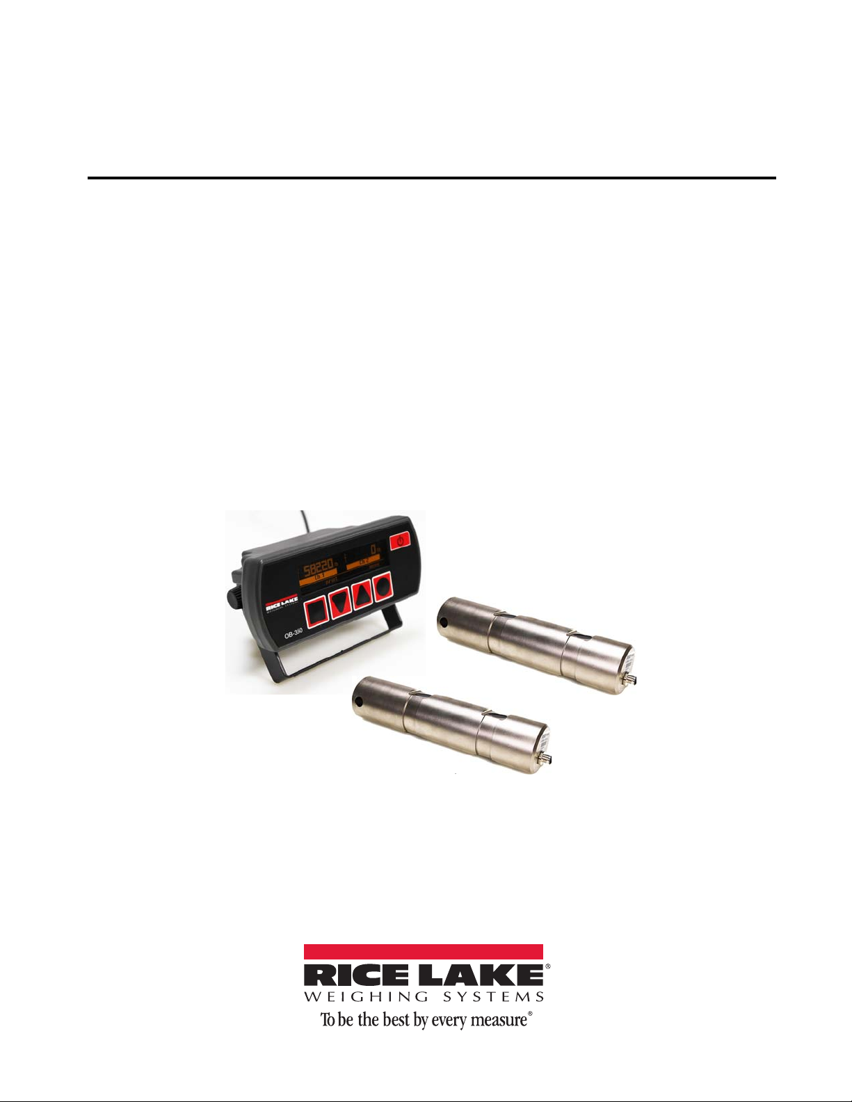
LoadRunner™Series
OnBoard Weighing System for Roll Off Trucks
Installation & Service
Manual
160913


i
Technical training seminars are available through Rice Lake Weighing Systems.
Course descriptions and dates can be viewed at www.ricelake.com/training
or obtained by calling 715-234-9171 and asking for the training department.
Content
Introduction.............................................................................................................................................. 1
Safety ....................................................................................................................................................... 1
1.0 Considerations Before Installation .............................................................................................. 2
1.1 Welding Specifications . . . . . . . . . . . . . . . . . . . . . . . . . . . . . . . . . . . . . . . . . . . . . . . . . . . . . . . . . . . . 2
2.0 Load Pin and Transducer Specification ...................................................................................... 3
2.1 Onboard Roll Off Kit Parts . . . . . . . . . . . . . . . . . . . . . . . . . . . . . . . . . . . . . . . . . . . . . . . . . . . . . . . . . 3
2.2 Load Pins . . . . . . . . . . . . . . . . . . . . . . . . . . . . . . . . . . . . . . . . . . . . . . . . . . . . . . . . . . . . . . . . . . . . . . 4
2.3 Pressure Transducer . . . . . . . . . . . . . . . . . . . . . . . . . . . . . . . . . . . . . . . . . . . . . . . . . . . . . . . . . . . . . 5
2.4 Roll Off Collar . . . . . . . . . . . . . . . . . . . . . . . . . . . . . . . . . . . . . . . . . . . . . . . . . . . . . . . . . . . . . . . . . . . 5
3.0 Roll Off Load Pin Installation ....................................................................................................... 6
3.1 Installing the Load Pins. . . . . . . . . . . . . . . . . . . . . . . . . . . . . . . . . . . . . . . . . . . . . . . . . . . . . . . . . . . . 6
3.2 Installing the Inclinometer . . . . . . . . . . . . . . . . . . . . . . . . . . . . . . . . . . . . . . . . . . . . . . . . . . . . . . . . . . 9
3.3 Power Cable Connection to Battery . . . . . . . . . . . . . . . . . . . . . . . . . . . . . . . . . . . . . . . . . . . . . . . . . 10
3.4 Hydraulic Pressure Transducer. . . . . . . . . . . . . . . . . . . . . . . . . . . . . . . . . . . . . . . . . . . . . . . . . . . . . 10
3.5 Routing Wiring . . . . . . . . . . . . . . . . . . . . . . . . . . . . . . . . . . . . . . . . . . . . . . . . . . . . . . . . . . . . . . . . . 11
3.6 Install the Indicator . . . . . . . . . . . . . . . . . . . . . . . . . . . . . . . . . . . . . . . . . . . . . . . . . . . . . . . . . . . . . . 12
3.6.1 Electrical Wiring and Data Connections . . . . . . . . . . . . . . . . . . . . . . . . . . . . . . . . . . . . . . . . . . . . . . . . 13
3.7 Final Installation . . . . . . . . . . . . . . . . . . . . . . . . . . . . . . . . . . . . . . . . . . . . . . . . . . . . . . . . . . . . . . . . 13
4.0 Configuration and Calibration ................................................................................................... 14
4.1 User and Setup Menu . . . . . . . . . . . . . . . . . . . . . . . . . . . . . . . . . . . . . . . . . . . . . . . . . . . . . . . . . . . 14
4.2 Initial Setup of the OB-350 Indicator . . . . . . . . . . . . . . . . . . . . . . . . . . . . . . . . . . . . . . . . . . . . . . . . . 15
4.2.1 Initial Password Entry and Clock Setup . . . . . . . . . . . . . . . . . . . . . . . . . . . . . . . . . . . . . . . . . . . . . . . . 16
4.2.2 Configuration of Input Channels . . . . . . . . . . . . . . . . . . . . . . . . . . . . . . . . . . . . . . . . . . . . . . . . . . . . . 16
4.3 Configuration of Count By . . . . . . . . . . . . . . . . . . . . . . . . . . . . . . . . . . . . . . . . . . . . . . . . . . . . . . . . 17
4.4 Configuration of Zero Function . . . . . . . . . . . . . . . . . . . . . . . . . . . . . . . . . . . . . . . . . . . . . . . . . . . . . 17
4.5 Configuration of Inclinometer Calibration . . . . . . . . . . . . . . . . . . . . . . . . . . . . . . . . . . . . . . . . . . . . . 17
4.6 Configuration of Modes . . . . . . . . . . . . . . . . . . . . . . . . . . . . . . . . . . . . . . . . . . . . . . . . . . . . . . . . . . 18
4.7 Calibration . . . . . . . . . . . . . . . . . . . . . . . . . . . . . . . . . . . . . . . . . . . . . . . . . . . . . . . . . . . . . . . . . . . . 18
4.7.1 Calculating the SPAN (Net Weight) . . . . . . . . . . . . . . . . . . . . . . . . . . . . . . . . . . . . . . . . . . . . . . . . . . . 18
4.7.2 Enter Tare Weight . . . . . . . . . . . . . . . . . . . . . . . . . . . . . . . . . . . . . . . . . . . . . . . . . . . . . . . . . . . . . . . . 19
4.7.3 Set Zero Calibration . . . . . . . . . . . . . . . . . . . . . . . . . . . . . . . . . . . . . . . . . . . . . . . . . . . . . . . . . . . . . . 19
4.7.4 Full Span (Net Load) Calibration . . . . . . . . . . . . . . . . . . . . . . . . . . . . . . . . . . . . . . . . . . . . . . . . . . . . . 20
5.0 Service and Troubleshooting..................................................................................................... 21
5.1 System Maintenance . . . . . . . . . . . . . . . . . . . . . . . . . . . . . . . . . . . . . . . . . . . . . . . . . . . . . . . . . . . . 21
5.2 Calibration . . . . . . . . . . . . . . . . . . . . . . . . . . . . . . . . . . . . . . . . . . . . . . . . . . . . . . . . . . . . . . . . . . . . 21
5.3 Sensor Maintenance. . . . . . . . . . . . . . . . . . . . . . . . . . . . . . . . . . . . . . . . . . . . . . . . . . . . . . . . . . . . . 21
5.3.1 Load Pins . . . . . . . . . . . . . . . . . . . . . . . . . . . . . . . . . . . . . . . . . . . . . . . . . . . . . . . . . . . . . . . . . . . . . . 21
5.3.2 Visual Inspection . . . . . . . . . . . . . . . . . . . . . . . . . . . . . . . . . . . . . . . . . . . . . . . . . . . . . . . . . . . . . . . . . 21
5.4 Cables and Connectors . . . . . . . . . . . . . . . . . . . . . . . . . . . . . . . . . . . . . . . . . . . . . . . . . . . . . . . . . . 22
5.4.1 Cables. . . . . . . . . . . . . . . . . . . . . . . . . . . . . . . . . . . . . . . . . . . . . . . . . . . . . . . . . . . . . . . . . . . . . . . . . 22
5.4.2 Connections . . . . . . . . . . . . . . . . . . . . . . . . . . . . . . . . . . . . . . . . . . . . . . . . . . . . . . . . . . . . . . . . . . . . 22
Hardware Warranty Statement .............................................................................................................. 23
© Rice Lake Weighing Systems. All rights reserved. Printed in the United States of America.
Specifications subject to change without notice.
Rice Lake Weighing Systems is an ISO 9001 registered company.
Version 1.0, April 16, 2014

ii On-Board Weighing Installation & Service Manual
Rice Lake continually offers web-based video training on a growing selection
of product-related topics at no cost. Visit www.ricelake.com/webinars.

1
Introduction
This manual is intended for use by technicians responsible for installing and servicing LoadRunner Series Onboard
Weighing Systems.
This manual contains instructions for installing various types of Onboard Weighing Systems (non Legal-for-Trade
systems). For straight trucks, this manual includes rigid under-body mounting instructions in four and six point
configurations, as well as under-body load pin installation instructions for tipping bodies and hoist chassis. Tipping
body installations can be either Lift-to-Weigh or Live-Weigh system types.
Authorized distributors and their employees can view or download this manual from the Rice Lake
Weighing Systems distributor site at www.ricelake.com.
Safety
Safety Symbol Definitions:
Important
CAUTION
WARNING
DANGER
Indicates an imminently hazardous situation that, if not avoided, will result in death or serious injury.
Indicates a potentially hazardous situation that, if not avoided, could result in serious injury or death, and
includes hazards that are exposed when guards are removed.
Indicates a potentially hazardous situation that, if not avoided, may result in minor or moderate injury.
Indicates information about procedures that, if not observed, could result in damage to equipment or
corruption to and loss of data.
General Safety
WARNING
Do not operate or work on this equipment unless you have read and understand the instructions and
warnings in this manual. Failure to follow the instructions or heed the warnings could result in injury or
death. Contact any Rice Lake Weighing Systems dealer for replacement manuals.
Proper care is your responsibility.
Failure to heed may result in serious injury or death.
DO NOT allow minors (children) or inexperienced persons to operate this unit.
DO NOT operate without all shields and guards in place.
DO NOT jump on the scale.
DO NOT use for purposes other than weight taking.
DO NOT place fingers into slots or possible pinch points.
DO NOT use any load bearing component that is worn beyond 5% of the original dimension.
DO NOT use this product if any of the components are cracked.
DO NOT exceed the rated load limit of the unit.
DO NOT make alterations or modifications to the unit.
DO NOT remove or obscure warning labels.
Keep hands, feet and loose clothing away from moving parts.

2LoadRunner™ Series Installation & Service Manual
1.0 Considerations Before Installation
WARNING
Failure to observe these recommendations and instructions could result in a hazardous
operating condition.
This manual is intended to provide information for the mounting of Onboard Weighing Systems sensors in a
variety of applications. In applying the installation procedures, which follow, some fundamental precautions and
recommendations must be observed by the installer:
• Rice Lake Weighing Systems’ Onboard Scales are designed for applications covering a broad range of
vehicle types. Things to take into consideration are:
- Significant variations in mountings
- Variations in load sensor models
- Specifications
- System configurations
• Installation procedures are similar for both new vehicle mountings and retro-fit mountings. When doing a
retro-fit mounting, ensure that all vehicle structures are free from cracks, excessive wear, corrosion,
alignment problems, etc. that could affect safety and scale performance.
• Load cells, load cell bearing plates, mounting brackets and load cell hardware should be painted upon
installation to help protect the installation from corrosion. Industry appropriate, quality enamel paint is
recommended.
- For environments where high concentrations of salts are used on road surfaces, under-body coating is
recommended (3M™ Underseal™ part number 3M-8883 Universal Rubberized Undercoating).
- Load cells, bearing plates, brackets and hardware should be periodically inspected for any evidence of
rust or corrosion. If areas of corrosion are present, they should be cleaned with a wire brush and
re-painted or undercoated.
- Load cell connectors must be connected or capped during painting or undercoating.
• The instructions outlined herein are designed to ensure that a correct installation will provide maximum
safety, optimum system performance and accuracy, a long operating life, and reasonable installation costs. It
is required that the installer comply with all guidelines and material specifications outlined in this manual,
with special emphasis on detail and inspection of work.
• Installation must comply with appropriate regulations of the U.S. Department of Transportation (DOT), state
and local regulations, the recommended standards and practices of the Society of Automotive Engineers
(SAE), standards of the American Welding Society (AWS), and the recommendations of the truck, trailer and
body, hoist and/or suspension manufacturer.
1.1 Welding Specifications
Welding, metalworking and assembly should only be performed by qualified personnel experienced in welding on
vehicle body structures and sub frames. Only welding equipment of the highest quality should be used in the
welding of load cell bearing plates. When welding, use procedures that ensure high quality welds. Over-welding
may result in distortion and damage, while under welding may not develop adequate strength.
Important
Rice Lake Weighing Systems recommends removal of load cell after tack welding bearing plates in
position so that final welding is performed without load cell being subjected to excessive heat, weld
current, or cable damage.
If welding with load cells in position, the installer must ensure that electrical current cannot flow through the load
cell. All load cell terminals must be shorted together. Attach the ground strap directly to the vehicle frame member
to which the bearing plates will be welded. Never weld directly to a load cell.
WARNING
Always disconnect battery terminals before performing any welding.

Load Pin and Transducer Specification 3
2.0 Load Pin and Transducer Specification
The Rice Lake Roll Off and Dump Truck kits are typically LIFT-TO-WEIGH KITS. This means that with the hoist
in the relaxed state (on the chassis), no weight reading is available. The hoist needs to be elevated to a position
showing the correct angle on the in-cab digital display unit, approximately 4 degrees, for the weight reading
degrees to be valid and accurate.
2.1 Onboard Roll Off Kit Parts
1, 2
3, 9
7
Battery
4
5
6
8
10
Figure 2-1. Onboard System – Roll-Off Kit Illustration
Table 2-1. Onboard System – Roll-Off Kit Parts List
Item No. Part No. Description Qty
1131204 Pin, Load Roll Off 2
2153104 Assy, Roll Off Kit 1
153098 Ring, Roll Off 4 OD x 2
153116 Nut, Top Lock 1/2-20 NF 2
153117 Screw, Cap 1/2-20NF x 5” 2
3131222 Inclinometer, Onboard 1
4131200 Transducer, Hydraulic 1
5131219 Indicator, OB3502 Channel 1
6131221 Cable Assembly Fuse 1
7131226 Splitter, Cable Y-Splitter 1
8131228 Cable Assembly 15’ (5M) 1
9158196 Bracket, Onboard Inclinometer 1
10 131800 Cable Assembly 6’ 3
4LoadRunner™ Series Installation & Service Manual
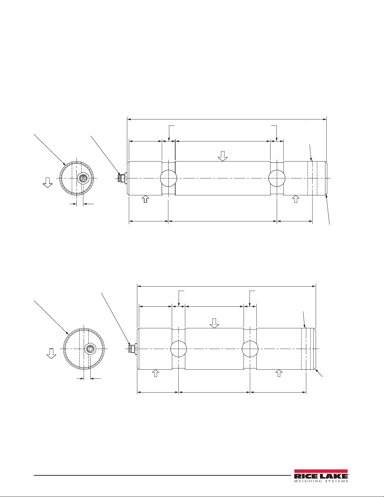
2.2 Load Pins
Hinge pivot and lift cylinder load pins built by Rice Lake Weighing Systems are available in two sizes:
• 2 inch diameter (see Figure 2-2) Dump Truck
• 2.5 inch diameter (see Figure 2-3) Roll Off
Full length hinge bars are also available as direct replacements for tipping bodies with hinge bars (contact a Rice
Lake Weighing Systems dealer or the factory). All load pins are supplied with collars and bolts with locknuts to
secure pin position. The installer must ensure that all load pin installations can receive required initial and periodic
lubrication.
Electrical
Connector
Double shear load pin
made from heat treated alloy steel
nickel plated for corrosion resistance
fitted with an M12 commercial vehicle class connector
11.8" (300 mm)
2"
(49 mm)
0.79"
(20 mm)
5.5"
(142 mm)
0.79"
(20 mm) 0.5 Ø (14 mm )
Orientation and
Anti-rotation
Reaction
Force
Reaction Force
2.4"
(62 mm)
6.4"
(162 mm)
2"
(53 mm) Chamfer
0.12"
(3 mm) x 45°
Both Ends
0.4"
(10 mm)
Ø 2" d10 Ø 50.70
50.58
Direction of Load
Direction
of Load
Figure 2-2. 2 Inch Diameter Load Pin (PN 131207)
0.4"
(10 mm)
2.5" Ø d10 Ø 63.40
63.28
Electrical
Connector
10.8" (275 mm)
2"
(51 mm)
0.79"
(20 mm)
3.5"
(90 mm)
0.79"
(20 mm)
Direction of Load
0.5 Ø (14 mm ) Hole
Orientation and
Anti-rotation
Reaction ForceReaction Force
2.5"
(64 mm)
4.3"
(110 mm)
3.3"
(86 mm)
Chamfer
0.12"
(3 mm) x 45°
Both Ends
Double shear load pin
made from heat treated alloy steel
nickel plated for corrosion resistance
fitted with an M12 commercial vehicle class connector
Direction
of Load
Figure 2-3. 2.5 Inch Diameter Load Pin (PN 131204)

Load Pin and Transducer Specification 5
2.3 Pressure Transducer
1.2" A/F
(30 mm) 0.25" (6 mm)
0.31"
(8 mm)
2" (50 mm)
1" Ø
(26 mm)
9/16"-18 SAE
1.2" Ø
(33 mm)
16' (5 M) if four core cable
with a M12 fully moulded male connector
Material: Stainless Steel
Sealing: Fully welded to IP68
Figure 2-4. Oil Pressure Transducer (PN 131211)
2.4 Roll Off Collar
Ø 4.00" (102 mm)
Ø 2.625" (66.675 mm) 1.50"
(38 mm) 0.625"
(16 mm)
Ø 0.530"
(13.5 mm)
Figure 2-5. Roll Off Collar (PN 153098)

6LoadRunner™ Series Installation & Service Manual
3.0 Roll Off Load Pin Installation
Load pins supplied are custom sized to fit the specific hinge and ram brackets of the vehicle. The LoadRunner Roll
Off system is compatible with Galbreath, Accurate and Ruddco. Installation requires removal of existing pins, and
replacements of these pins with Rice Lake load pins and collars.
Important
All load pin installations require lubrication facilities. Normally lubrication is provided through the central
pivot area.
OEM Roll Off pivots typically have existing lubrication fittings included in their pivots. Rice
Lake pivots are furnished with drilled and tapped holes for the insertion of a standard lube zirk which
must be supplied and installed by the system installer.
Load
Pins
Inclinometer
Y Cable
Battery
Transduce r
Indicator
Power Cable
Homerun Cable
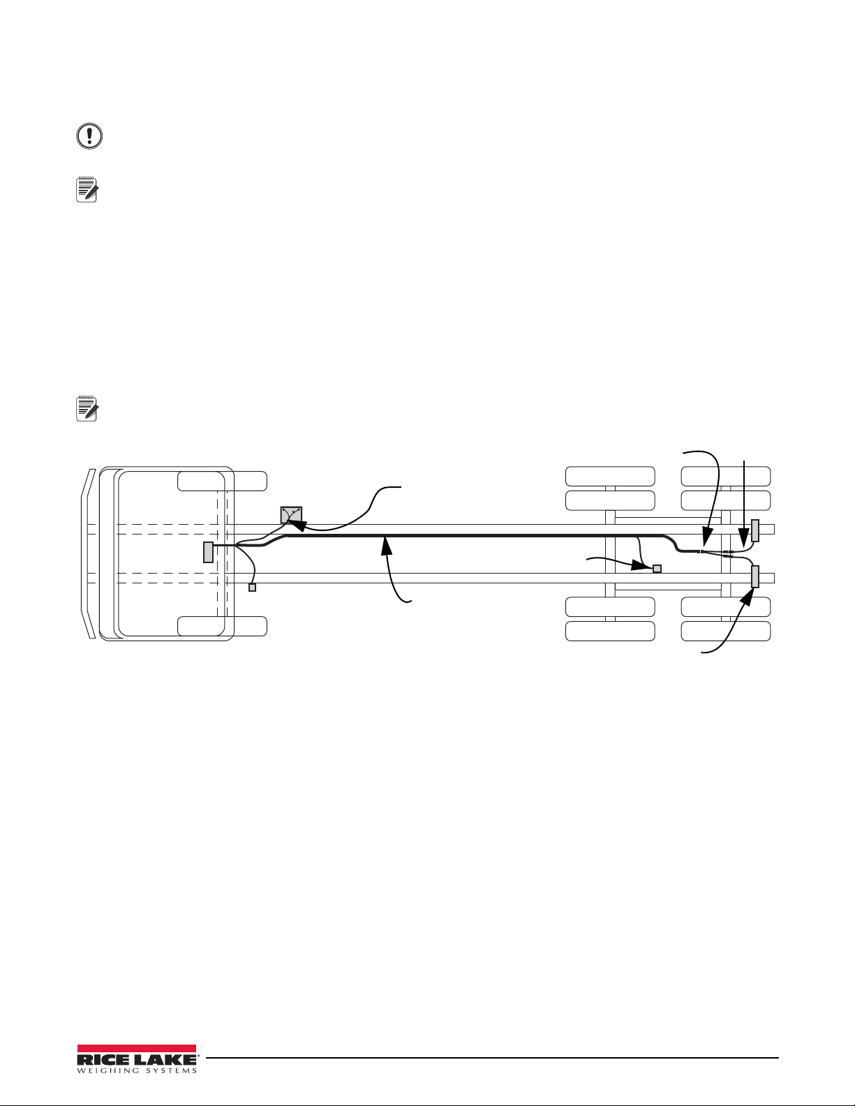
Figure 3-1. LoadRunner System Layout
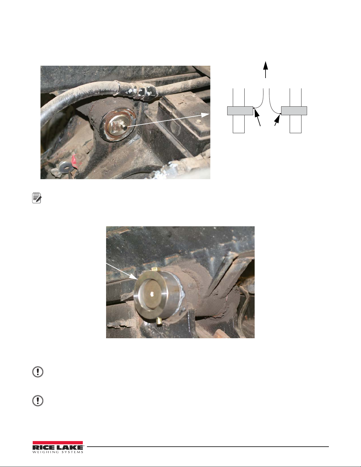
3.1 Installing the Load Pins
1. Remove the rear fenders from the truck, if required, to gain free and clear access to the pivots.
2. Use jacks or a forklift to support therear of the hoist chassis and maintain its position/alignment while the
pivot pins are being replaced.
3. Remove the bolt and washer from the outer collar on the pivot.
Note
Removing pivot pins on some vehicles may be difficult if rust is present or if the hoist chassis pivot and the truck
chassis supports are out of alignment. If rust is an issue, use a penetrating lubricant and appropriate tools for
tapping the pivot pin out. Use a pry bar as a lever to assist with any misalignment problems to remove the
existing pivot pins.
4. Push the pivot pins into the frame and out the other side, removing the inside collar as well.
5. Remove the outer collar if still attached to the frame.
6. Using a power grinder or a wire brush, clean around thehole where the pivot was located, both sides of the
frame.
7. Grind the frame smooth to ensure a clean weld at load cell installation.
8. Remove any debris that is inside and around the holes of the chassis supports and the pivots.
Remove existing pin and
prepare surface for load
pin installation
Figure 3-2. Remove Existing Pin
Roll Off Load Pin Installation 7
9. Using grease, lubricate the hole and insert the load pin into the frame ensuring the strain gauge seals are
facing toward the front of the truck. The load pins have arrows indicating the downward force, or direction
of load applied to register a positive weight value.
The load pin should extrude from the outside of the frame 4 inches.
Left Rear – Connector should face toward cab.
Right Rear – Connector should face away from
cab
Cab of Truck
Load Pins
Connectors
Figure 3-3. Install Load Pin
Note
See Figure 2-2 and 2-3 for load pin specifications and load direction.
10. To install the collar kit, place collar on the load pin aligning the holes and secure with bolt. Pin should go in
from the top and be vertical. Use a small square to ensure the bolt is precisely vertical.
Collar and bolt
Figure 3-4. Install Collar and Bolt
11. Tack weld the collar to the frame to hold in place.
Important
Important
DO NOT overheat the load pin when tack welding. This may damage the load pin. Do not exceed 140° F.
12. Remove the load pin from the frame.
Load pin should be easily removed by hand. If not, use a wood block (or similar material) to cushion the
load pin, and tap lightly to remove.
Do NOT strike the load pin directly, it may cause damage to the load pin.
13. Skip-weld the collar to frame with four welds of 1 inch each, is adequate. However if the installer prefers,
the entire collar can be welded in place. Allow collar to cool before proceeding to next step. Ensure there
are no weld remnants inside the collar or pivots. Remove any such residuals.

Skip weld collar to frame
Note
8LoadRunner™ Series Installation & Service Manual
Leave access to easily install the bolt and nut that secures the load cell.
Figure 3-5. Skip Weld Collar to Frame
14. Apply grease to each center pivot using existing lubrication points.
15. Reinstall the load pin, lining up the bolt hole with the hole in the collar.
1/2-20 x 5”
Screw
Load Pin
Important
Do NOT strike the load cell directly, as it may cause damage to the load cell. Use a wood block (or similar
material) to cushion the load cell, and tap lightly. If the load pin does not go in by hand, or with moderate
tapping, the holes need to be aligned better, or opened up with a grinder.
16. Insert bolt through the top of the collar and secure with nut at the bottom.
Figure 3-6. Insert Load Pin
17. Repeat steps 3through 16 for the other side of truck.

Roll Off Load Pin Installation 9
3.2 Installing the Inclinometer
Inclinometer should be installed on the hoist as close as possible to the load pins. Grind off any paint or rough areas
of the frame.
Inclinometer Bracket
Hoist Frame
Inclinometer
Important
The inclinometer should be installed on a flat surface that will not interfere with any moving parts on the
frame. It must be installed as level to the frame as possible.
Figure 3-7. Install Inclinometer
Note
Rice Lake Weighing Systems recommends one of the following mounting options, dependant on the type of
truck frame the unit is being mounted to.
Mounting Bracket Option 1
1. Align the mounting bracket to the frame and mark the holes.
2. Set the bracket aside and drill holes in the frame where marked.
3. Align the bracket with the holes and secure with bolts, washer and nuts.
Mounting Bracket Option 2
1. Align the mounting bracket to the frame and mark the holes.
2. Weld mounting studs tot he frame where marked.
3. Place the bracket on the mounting studs and secure with washers and nuts.
Mounting Bracket Option 3
1. Align the mounting bracket to be level with the frame.
2. Weld around the bracket to secure to frame.
Installing Inclinometer
1. Install the inclinometer to the bracket using the hardware included. The cable connection should be at the
bottom.
10 LoadRunner™ Series Installation & Service Manual
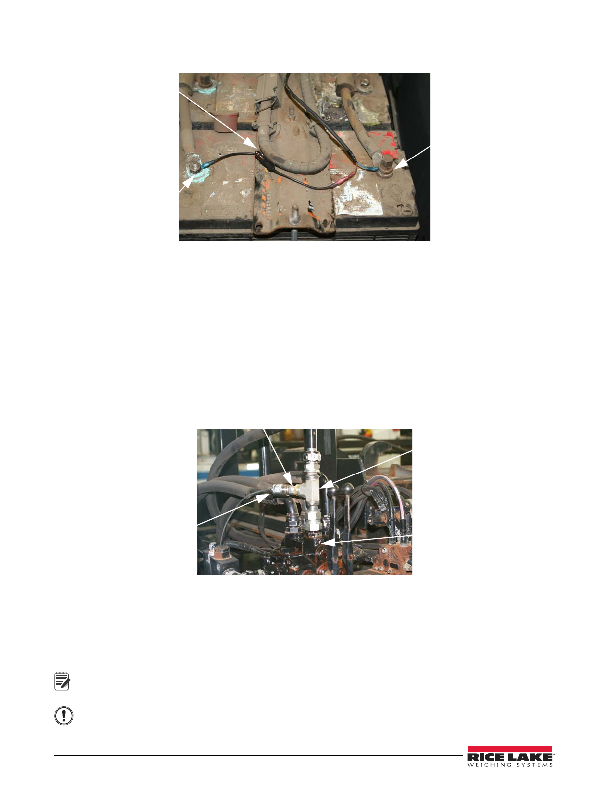
3.3 Power Cable Connection to Battery
Brown wire to positive
Fuse
Blue wire to negative
Figure 3-8. Power Connection to Battery
1. Wire the fuse (5A) to the brown wire.
2. Connect the power cable to the battery.
- Brown wire connects to positive terminal.
- Blue wire connects to ground.
3.4 Hydraulic Pressure Transducer
The hydraulic pressure transducer should be installed at the hydraulic control valve.
Tee Fitting
Reducing Fitting
Transducer
Hydraulic Valve
Figure 3-9. Install Hydraulic Pressure Transducer
1. Remove the hose where the transducer is to be installed.
2. Install a tee fitting to connect the hose to the hydraulic valve.
3. Insert a reducer if required (9/16”straight thread with O-ring is required to fit the Rice Lake pressure
transducer) to the opening in the tee where the transducer is to be installed.
4. Run the cable along the frame to the cable access hole in the cab. Wire-tie the cable to the frame.
Important
Note
Allow for slack when fitting and securing hydraulic hose lines as these move during normal operation.
Plan a transducer cabling route that has little or no risk of pinching, stretching or melting the cables.
Use split loom on all exposed cable to protect in areas where damage could be an issue.
Roll Off Load Pin Installation 11
3.5 Routing Wiring
Because each truck is different, cable routing will be specific to the truck the system will be installed on.
Important
Plan a route that has little or no risk of pinching, stretching or melting the cables.
Use split loom on all exposed cable to protect in areas where damage could be an issue.
Wire tie any excess cable to the frame.
Note
For cab-over type truck cabs, all scale system cabling must run around the main pivot point of the cab-over
hinge. For conventional cabs, look for cab access grommets in the flooring near the driver seat area.
For ease of connection, label the cables used in installation prior to threading through the hole into the cab.
1. Connect 6’ cables to the load pins.
2. Connect the load pin cables to the Y cable.
3. Connect 15’ cable and 3’ cable (if necessary) to the Y cable.
4. Route the 15’ cable along frame to the indicator through access hole in the cab.
5. Wire tie the cable to the frame approximately every 18 inches.
6. Follow the same route with the inclinometer cable.
7. Route the power cable from the battery to the indicator location.
Load
Pins
Inclinometer
Y Cable
Battery
Transduce r
Indicator
Power Cable
15’ Cable
6’ Cable
Note
Connecting wiring to the indicator is shown in Section 3.6.
Figure 3-10. Wiring Diagram
12 LoadRunner™ Series Installation & Service Manual
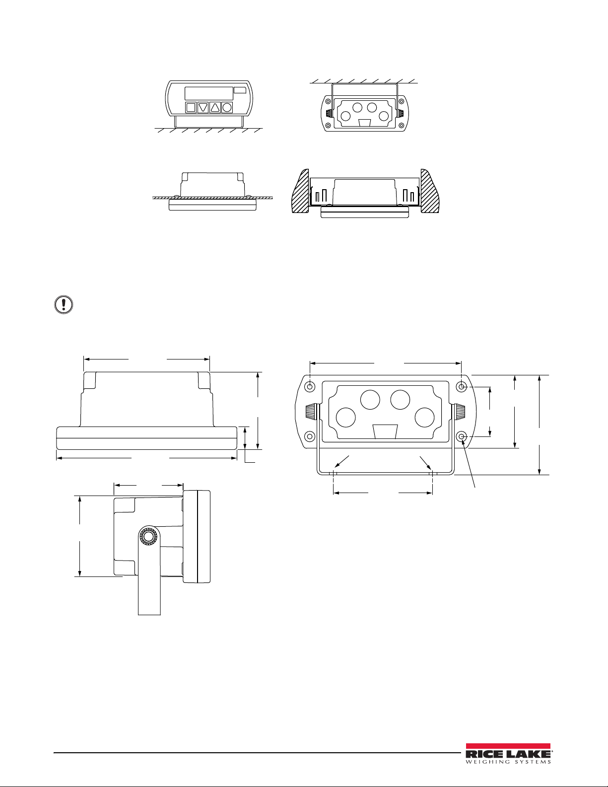
3.6 Install the Indicator
Panel mount
Roof/under dash mount
Dash mount
Optional Radio DIN mount
Figure 3-11. Indicator Mounting Options
If the indicator will be installed in the cab, choose an area that is easily visible to the driver. A mounting bracket is
provided.
0.71 in
(18 mm)
4.00 in
(100.5 mm)
2.50 in
(62.5 mm)
5.71 in
(145 mm)
1.73 in
(44 mm)
5.71 in
(145 mm)
4.80 in
(122 mm)
1.57 in
(40 mm)
2.32 in
(59 mm)
3.54 in
(90 mm)
3.54 in
(90 mm)
Ø 0.25 in (6.5 mm)
holes for u-brackets
0.157 in (4 mm) self taper
0.137 in (3.5 mm) deep
Panel mount holes
Important
When running cable to the indicator, use existing access hole if available, if not, a hole will need to be
drilled in the cab. Insert a grommet to protect wiring.
Do not allow cable jacket to contact bare metal edges.
Figure 3-12. Indicator Dimensions
Roll Off Load Pin Installation 13
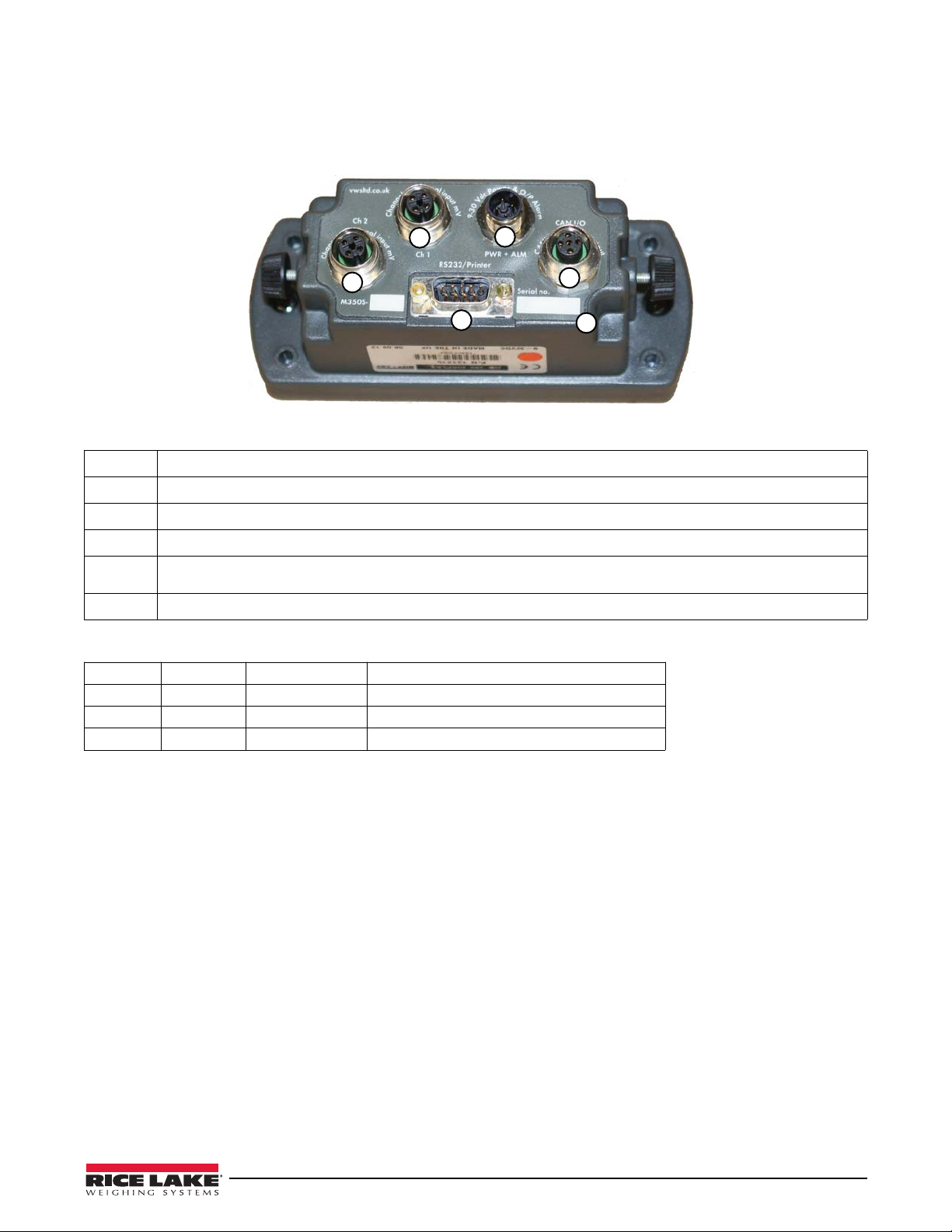
3.6.1 Electrical Wiring and Data Connections
The indicator is fitted with one Power and one Input Channel connector as standard. CANbus, Channel 2 and RS-232 are optional.
Full connector options are shown below.
13
24
56
12B1D4FB
T
Figure 3-13. Rear Panel Identification and Bulkhead Connectors
1Input Channel 1, Max +/-39.0625 milli-Volts (Hydraulic Pressure Transducer)
2Input Channel 2, Max +/-39.0625 milli-Volts (Load Pin Connection)
3Power Input
4CANbus digital input & output (Inclinometer Connection)
5
RS-232 output for printers and data capture devices (pin 9 = vehicle volts, pin 5 = ground, pin = 2 transmit, pin 3 =
receive)
6Alpha-numeric unique indicator serial number, also appears on power-on
POWER & ALARM, socket is MALE – CON 1 on PCB
Pin 1 BROWN Vehicle voltage Supply 12V (LCV) or 24V (MCV & HGV)
Pin 2 WHITE Output 1 12V or 24V
Pin 3 BLUE Ground Ground 0 Volts (common)
Pin 4 BLACK Output 2 12V or 24V
3.7 Final Installation
1. Reinstall the fenders.
2. Test the hoist to make sure none of the cables at risk of being pinched, stretched or cut when it is raised and
lowered.
3. Test the hoist to make sure the scale reads positively with applied weight. If positive weight is not
displayed, it is possible that the load pins or a load pin are not in the correct position and reading
backwards. Pin position can be changed by rotating 180 degrees.
14 LoadRunner™ Series Installation & Service Manual
4.0 Configuration and Calibration
4.1 User and Setup Menu
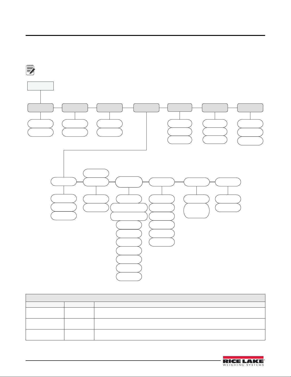
The menu structure has two levels of security: an open user menu for driver operators and a password setup menu
for calibrations and options for making changes to the user menu.
Note
OptionsAlarms
Alarm 1
Alarm 2
Cells
CAN
Diagnostics
Menu
OLED
Info
Display
Split
Input 2
Input 1
Configuration
Span
Zero
Tare
Calibration
Modes RS-232
PRINTER Count
1 lb
10 lb
20 lb
50 lb
100 lb
200 lb
INC
ON
OFF
System
PUK
Pin
Clock
Net
Gross
Net & Gross
ON
OFF
Chan
Load
Z/Func
Keyboard
Inhibit
Keyboard
Printer
Printer CSV Data
Printer G PVWS
None
Format 1-4
Scoreboard
Net 4
Gross 4-5
G PVWS
BA4840
The default password is 0350. Keep this for your records.
Figure 4-1. User and Setup Menu – Electrical Wiring and Data Connections
User and Setup Menu
Parameter Choices Description
Display OLED
Info
Adjust the brightness of the display; High, Med or Low.
Firmware version and serial number display.
Diagnostics Cells
CAN
To display mV/V for load cells or transducers on seperate channels.
To display CANbus diagnostics (not used).
Alarms Alarm 1
Alarm 2
Allows configuration of audible alarms.
Table 4-1. User and Setup Menu – Electrical Wiring and Data Connections

Configuration and Calibration 15
The following configuration and calibration instructions require symbols to make selections. When selecting a
symbol, press the corresponding key below the symbol. See Figure 4-2.
(OK)
Symbols
Keys
Figure 4-2. Symbol Keys
4.2 Initial Setup of the OB-350 Indicator
The system password allows access modification of the options: Configuration, Calibration and System Setup
menus. When in the configuration and setup menus, the function keys will perform the following functions:
M
E
N
U
(OK)
Diagnostics
Alarms
Options
Configuration
Calibration
System
A B C D
E
Figure 4-3. Setup Mode
AAccept or Enter key - enters data
BDown arrow key - scrolls down within the menu selection
CUp arrow key - scrolls up within the menu selection
D
Carriage Return/Circle - Previous screen or back function
When in a menu function (password) and OK is not visible, use this key as the enter and accept.
ESelectable MENU options
Options Modes Select weighing mode to be displayed - Net. Gross or Net & Gross. See Section 4.6.
Load/Chan Load function gives the option to accumulate the amount of load (weight) delivered or
collected from site.
Channel Function - Split screen function is added to the MENU screen.
RS-232 Select or change RS-232 output option.
Count Select count by in kg - 1, 2, 5, 10, 20, 50, 100, 200,
Z/Func Allows operator access to Zero/Tare function on the display.
Inc For use with roll off systems and dump trucks, turn on to calibrate zero degrees of
inclinometer.
Configuration Input 1(F)
Input 2 (R)
Split
CAN
Air/Oil pressure transducer or load cell setting on truck type.
Air/Oil pressure transducer or load cell setting on truck type.
Setting varies depending on input 1/input 2 values.
Not Used
Calibration Tare
Zero
Span
Entry of empty vehicle weight for gross weight calculation.
No load zero calibration.
Entry of load for span calibration.
System Pin
PUK
Clock
Enter a password.
Not Used.
Change system time and date.
User and Setup Menu
Parameter Choices Description
Table 4-1. User and Setup Menu – Electrical Wiring and Data Connections
Table of contents


