4
Verwenden Sie engmaschig geschirmte Leitungen mit
Querschnitt 0,75 mm2, z.B. Typ Ölflex 415 CP3 X 0.75.
Die Messköpfe können im 3-Drahtanschluss oder im
5-Drahtanschluss betrieben werden.
3-Drahtanschluss: Bei Leitungslängen bis 750 m
und geringen Temperaturschwankungen. Der
Spannungsabfall an der Leitung kann durch die Wahl
eines Betriebsprogrammes mit höherer Versorgungs-
spannung ausgeglichen werden. Messen Sie die
Versorgungsspannung am Messkopf an den Klemmen 2
(+) und 4 (-). Ist die gemessene Spannung um mehr als
0,1 V niedriger als in der Programmliste angegebenen,
stellen Sie am Control Modul ein Betriebsprogramm mit
einer entsprechend höheren Versorgungsspannung ein.
Prüfen Sie am Messkopf noch einmal die Versorgungs-
spannung auf den richtigen Wert.
Ist kein geeignetes Programm verfügbar, wechseln Sie
auf 5-Drahtanschluss.
5-Drahtanschluss: Bei Leitungslängen über 750 m
oder großen Schwankungen der Umgebungstemperatur.
Mit den beiden zusätzlichen Senseleitungen kompensiert
das Control Modul alle leitungs- und temperaturbedingten
Schwankungen der Messkopfversorgung selbstständig.
Die maximale Leitungslänge beträgt 3000 m.
Achtung:
Beachten Sie unbedingt die Bedienungsanleitung des
Control Moduls bei der Inbetriebnahme!
Wählen Sie vor dem Anschluss des Messkopfes das
entsprechende Betriebsprogramm. Ein falsch einge-
stelltes Betriebsprogramm kann zur Zerstörung des
Sensors führen!
Legen Sie den Schirm der Leitung nur einseitig auf!
Nach dem Anschluss muss eine Justierung mit
Prüfgas durchgeführt werden (siehe Kapitel 5).
Diese kann entfallen, wenn eine werksseitige
Linienkalibrierung bestellt wurde. Die Komponenten
sind dann entsprechend gekennzeichnet.
Der Messkopf darf nicht mit Konstantstrom betrieben
Werden. Dies kann zur Zerstörung des Sensors führen!
Use shielded cable with wire cross section 0,75 mm2, e.g.
type Oelflex 415 CP3 X 0.75. The sensor heads can be
operated in a three or a five - wire mode.
3-wire mode: for cable lengths up to 750 m and little
variations of ambient temperature. The voltage drop in the
cable can be compensated by selecting a program with
higher sensor supply voltage. Measure the supply voltage
at terminals 2 (+) and 4 (-). If the measured voltage is
more than 0.1 V lower than specified in the program list,
select a program with a sensor supply voltage, which is
higher than the active program. To determine the new
program add the value of the voltage drop to the existing
voltage and select a new program corresponding to the
resulting value (see program list of control module). Check
the sensor supply voltage again.
If no appropriate program is available, change to 5-wire
mode.
5-wire mode: in case of cable length above 750 m or
significant variations of ambient temperature.
Two additional sense wires measure the actual sensor
supply voltage. The control module will compensate supply
voltage variations automatically if required.
The maximum cable length is 3000 m.
Attention:
To start up, we recommend to observe the operating
instructions of the control module!
First select the appropriate operating program.
Selecting the wrong program may destroy the sensor!
Connect the cable shield to one side only in order to avoid
ground loops!
After the installation the sensor head must be
calibrated with span gas (see chapter 5) as far as it
has no ex-works line calibration. Ex-works-calibrated
components have labels with all relevant information on
them.
Never operate the sensor head in the constant current
mode. This may damage the sensor.
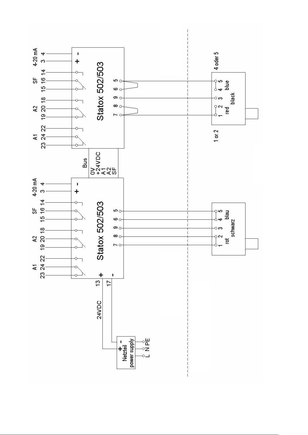
Anschluss an Statox 502/503 Control Module
Connection to a Statox 502/503 Control Module
Wählen Sie das entsprechende Betriebsprogramm am
Statox 502 oder Statox 503 Control Modul. Beachten Sie
dazu die Bedienungsanleitung des Control Moduls und die
dazugehörige Programmliste.
Messkopf HRC: Prog. Nr. 12
Messkopf ARE: Prog. Nr. 6
Messkopf LCIR: Prog. Nr. 12
Messkopf MCIR: Prog. Nr. 12
Messkopf für 0-10 Vol% CO2: Prog. Nr. 70
Messkopf für 0-100 Vol% CO2: Prog. Nr. 71
Schließen Sie nun den Messkopf an (siehe Bild 2).
Select the relevant program at the Statox 502 or Statox 503
control module. Observe the operating instructions of the
control module and the corresponding program list.
Sensor head HRC: prog. no. 12
Sensor head ARE: prog. no. 6
Sensor head LCIR: prog. no. 12
Sensor head MCIR: prog. no. 12
Sensor head CO20-10 % Vol.: prog. no. 70
Sensor head CO20-100 % Vol.: prog. no. 71
Then connect the sensor head (see pct.2).