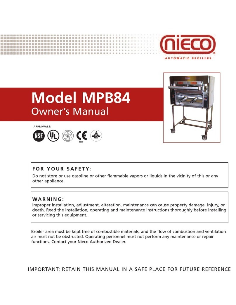
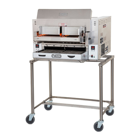
Nieco MPB94 Operating manual

Nieco MPB94 Gas
Preventative Maintenance
Guide
May 16, 2017
Final

Procedures
Preventative Maintenance should be performed every 12 months
PM should be scheduled either after closing or prior to opening
1. Inspect power supply cord and cap. Check cap for signs of overheating. Check cord for cracks and
breaks.
2. Inspect gas hose and connections for cracks and leaks
3. Inspect all four wheels/casters. Replace any that are bent or not turning properly. Tighten any that
are loose.
4. Remove all the daily, weekly and monthly parts from the broiler and inspect. Make note of any
broken or abused parts. Straighten any bent sheet metal parts.
5. Inspect all the PTFE bearings and replace if needed
6. Inspect flame arrestors for breaks and warping from heat.
7. Inspect lower and upper burners for cracks and plugged burner ports.
8. If equipped, Inspect the Incendalyst for damage and cleaning. Clean with water only.
9. Inspect high temperature wires for cracking and breaking at element connections
10. Inspect high temperature wires for burning at relay and contactor connections
11. Fill out PM inspection form.
Required Maintenance
1. Lubricate drive and feeder chains
2. Replace both feeder clutch plastic bushings
3. Replace hot surface igniter
4. Replace flame sensor and wire
5. Remove all mounting clips from upper heating elements if present
6. Replace all main burner orifices
7. Replace all pilot orifices, including zip tube orifice
8. Adjust all gas pressures
9. Calibrate broiler

Inspection Sheet
Restaurant Number ____________ Date: ______________________
Serial Number ________________
Inspected and good condition
Needs follow up service
Needs Immediate service or replacement
Service or replacement completed
COMPONENT CHECK
1 Inspect Power cord and plug
2 Inspect Casters, make sure they are tight to frame, no flat spots and roll properly
3 Inspect Panels and all other removable parts
4 Inspect Gas hose and supply. Check hose for gas leaks with bubbles
5 Inspect restraining cable and fastenings
6 Inspect broiler frame (cross rods & supports)
7 Remove and Inspect lower burners
8 Inspect flame arrestors
9 Inspect Incendalyst (Catalyst)
10
Remove and inspect upper burners
11
Inspect all wiring connections in control box, tighten all high voltage connections
12
Inspect control box for grease or water (clean if needed)
13
Inspect and adjust both feeders
14
Inspect all high temperature wires and connections at elements
15
Remove all heating element retaining clips if present
16
Flex side heating elements total amps _____________
17
Main side heating elements total amps _____________

Assembly

Assembly

White PTFE Bearings
FEED END DISCHARGE END
P/N 6047 P/N 6046
P/N 6049 P/N 6049
1. Inspect all 4 PTFE Bearings and replace if worn
Example

Flame Arrestors
Old Style
This is a one piece design and the
entire arrestor must be replace if
there are any holes or excessive
warping. Replace with the new
style flame arrestor
New Style
This Flame Arrestor is a frame
assembly and two replaceable
arrestor screens. With this design
you replace only the defective
screen.
Old style Flame Arrestor
P/N 16202
New style Flame Arrestor
P/N 19970
Replaceable Arrestor
screens
P/N 19980

Lubricate all Drive Chains
1. Remove cover and lubricate Drive Chains. (2 chains)(We suggest using high
temperature grease)
2. Remove cover and lubricate Feeder Chains. (Main and Flex sides) (We suggest using
high temperature grease)
3. Remove feeder drive and replace white shoulder bushing
4. Install feeder assembly and align pin with feeder
Shoulder Bushing
Feeder Chain
Drive Chains (2)

Replace Ignition Parts
Hot Surface Igniter
Flame Sensor
1. Replace the Hot Surface Igniter
2. Replace the Flame Sensor
Hot Surface Igniter Flame Sensor
Note: Broilers built in 2006 require
snap in flame sensor and separate
spark wire.

Elements
1. If present, remove all the mounting clips for the upper heating elements on both the main
and flex side of the broiler and discard.
2. Inspect all elements for cracks, bowing and excessive corrosion.
Element
Mounting Clip

Replace Pilot Burners
Upper Pilot Burner
P/N 2180
Lower Pilot Burner
P/N 2179

Orifice Replacement
Note: Orifices sizes are
for non CE broilers
3 1 3
1 2 4 6 3 3
Orifices Natural Gas
#
Description Part # Qty
1
Orifice, Pilot #3225
2182 2
2
Orifice, Zip Tube #75
2185 1
3
Orifice, Main Burner, #42
16590 4
4
Orifice, Main Burner, #46
2051 1
5
Orifice, Main Burner, #45
14045 1
Orifices LP Gas
#
Description Part # Qty
1
Orifice, Pilot #4214
17276 2
2
Orifice, Zip Tube #80
2186 1
3
Orifice, Main Burner, #54
2065 4
4
Orifice, Main Burner, #56
2064 1
5
Orifice, Main Burner, #56
2064 1

Set Gas Pressures
Dungs Valve Adjustment
Setting the pressures and calibration
1. Assemble the broiler and connect power and gas
2. Attach Manometer to the Gas Test Port on the main gas valve
3. Turn on the broiler and set the load sensor control to 800F
4. Reoe the high gas adjustet sre oer ad set the high gas pressure to . WCI .WCI for LPG
5. Change the load sensor control to 250F
6. Usig the Lo Gas Adjustet, set the lo gas pressure to WCI 8 WCI for LPG
7. Move the manometer to the test port located on the main gas manifold
8. Change the load sensor control to 800F
9. Reoe the gas regulator sre oer ad adjust the pressure to WCI 8 WCI for LPG
10. Calibrate the broiler
High Gas Adjustment Low Gas Adjustment Gas Test Port
Gas Regulator
Manifold Test Port

Set Gas Pressures
Honeywell Gas Valve adjustment
Setting the pressures and calibration
1. Assemble the broiler and connect power and gas
2. Attach Manometer to the output test port on the main gas valve
3. Turn on the broiler and set the load sensor control to 800F
4. Usig the High Gas Adjustet, set the high gas pressure to . WCI .WCI for LPG
5. Change the load sensor control to 250F
6. Usig the Lo Gas Adjustet, set the lo gas pressure to WCI 8 WCI for LPG
7. Move the manometer to the test port located on the main gas manifold
8. Change the load sensor control to 800F
9. Usig the gas regulator, adjust the pressure to WCI 8 WCI for LPG
10. Calibrate the broiler
Gas Regulator
Manifold Test Port
Low Gas
Adjustment
High Gas
Adjustment
Test Port
Shut off
Valve

Calibrate Broiler
Automatic
calibration
Display will show
60 minute
countdown
Automatic Calibration
A. Before turning the broiler on, press
and hold the load sensing control
knob/button in
B. Turn the main power switch to
position 2 and continue to hold the load
sensing control knob/button in for 5
seconds.
C. After 5 seconds, release the
knob/button. The control will display a
countdown of 60 minutes. After the
countdown the control will display
rdy ad the roiler ill e alirated.
DO NOT COOK DURING CALIBRATION

Parts Required
Description Part # Qty
Shoulder Bushing
14896 2
Igniter, Hot Surface
10291 1
Sensor, Flame (snap in)
16857 1
Machines built in 2006
Sensor, Flame
W/wire 25957 1
Machines built after 2006
Burner, Pilot
2180 1
Burner, Pilot
2179 1
PTFE Bushing
6049 2
PTFE Bushing
6046 1
PTFE Bushing
6047 1
Orifices Natural Gas
Description Part # Qty
Orifice, Pilot #3225
2182 2
Orifice, Zip Tube #75
2185 1
Orifice, Main Burner, #42
16590 4
Orifice, Main Burner, #46
2051 1
Orifice, Main Burner, #45
14045 1
Orifices LP Gas
Description Part # Qty
Orifice, Pilot #4214
17276 2
Orifice, Zip Tube #80
2186 1
Orifice, Main Burner, #54
2065 4
Orifice, Main Burner, #56
2064 2
Other manuals for MPB94
2
Table of contents
Other Nieco Commercial Food Equipment manuals