Nielsen 1000-1161 Series Technical Document

CONFIDENTIAL AND PROPRIETARY INFORMATION Copyright © 2014 The Nielsen Company. All rights reserved.
Equipment Manual:
Encoder 1000-1161
Date: June 2014
Document #: 1050-1475
Revision: F
For Nielsen Audio Encoder Model:
1000-1161-xx 1U SGE Digital Encoder, ROHS Compliant
Distribution of this document outside of Nielsen is subject to Non-Disclosure Agreement.
NIELSEN CONFIDENTIAL AND PROPRIETARY INFORMATION
Copyright © 2014 The Nielsen Company. All rights reserved. This equipment manual is intended for
use only by authorized Nielsen customers. Should you receive a copy of this equipment manual in
error, contact the Nielsen Legal department as indicated on page 8. This equipment manual may not
be reproduced or referenced, in whole or part, without the express written consent of Nielsen. Posting
to any website or FTP site requires the express written consent of Nielsen. This equipment manual
and the information contained within is intended for Nielsen customers or authorized recipients only;
any reference or its use, in whole or part, for any other purpose without express written permission
from Nielsen is expressly prohibited. Nielsen Audio Encoders are covered by one or more U.S. Patent
Numbers and their corresponding international patents, and other patents may be pending. This
equipment manual includes proprietary and technical information which is the intellectual property of
Nielsen. Nielsen and the Nielsen logo are trademarks or registered trademarks of CZT/ACN
Trademarks, L.L.C. Patents: http://www.arbitron.com/home/patents.htm
Any brand names, product names, or titles used or referenced herein are trademarks, trade names
and/or copyrights of their respective holders. All images are used for purposes of demonstration only,
and the entities associated with the products shown in those images are not affiliated with Nielsen in
any way, nor have they provided endorsements of any kind. No permission is given to make use of
any of the above, and such use may constitute an infringement of the holder’s rights.

Equipment Manual: Encoder 1000-1161
Document #: 1050-1475
Revision: F
CONFIDENTIAL AND PROPRIETARY INFORMATION
Copyright © 2014 The Nielsen Company. All rights reserved.
2
Table of Contents
Nielsen Audio Trademarks Included 6
Contacts 8
Disclaimer and Limitation of Liability 9
Notices 10
1. Introduction 11
1.1. Suggested Placement in Audio Chain 12
2. Installation 13
3. Operations 17
3.1. Initiating Encoding 17
3.2. Immediately After Placing the Encoder On-Air 17
3.3. Bypass Features 17
3.3.1. Power-Off Bypass 18
3.3.2. Master Bypass 18
3.3.3. Bypass Mode Remote Monitor 18
3.3.4. Bypass Mode Remote Control 19
3.4. Alarm Status Remote Monitoring 20
3.5. Theory of Operation for the Status and Control Relays 21
3.6. Using the LCD Menu 23
3.7. Encoder Overheat Behavior 24
4. Audio Input Specification 25
5. Digital SGE Specifications 25
5.1. Digital I/O Interface, XLR 25
5.1.1. Input Data Format and Transmission Standards 25
5.1.2. Connectors 25
5.1.3. Input Characteristics 25
5.1.4. Minimum Input Working Voltage 25
5.1.5. Maximum Input Working Voltage 25
5.1.6. Maximum Absolute Input Voltage 25
5.1.7. Sampling Frequency of Data 25
5.1.8. Range of Input Frequency 25
5.1.9. Output Characteristics 26
5.1.10. Minimum Output Voltage into 11026
5.1.11. Maximum Rise/Fall Time 26
5.1.12. Output Jitter 26
5.1.13. Input to Output Delay 26
5.1.14. Maximum Cable Length 26

Equipment Manual: Encoder 1000-1161
Document #: 1050-1475
Revision: F
CONFIDENTIAL AND PROPRIETARY INFORMATION
Copyright © 2014 The Nielsen Company. All rights reserved.
3
5.2. Digital I/O Interface, BNC 27
5.2.1. Input Data Format 27
5.2.2. Transmission Standard 27
5.2.3. Connectors 27
5.2.4. Input Characteristics 27
5.2.5. Minimum Input Working Voltage 27
5.2.6. Maximum Input Working Voltage 27
5.2.7. Maximum Absolute Input Voltage 27
5.2.8. Sampling Frequency of Data 27
5.2.9. Range of Input Frequency 27
5.2.10. Output Characteristics 27
5.2.11. Output Voltage into 7527
5.2.12. Range of Rise/Fall Time 27
5.2.13. Output Jitter 28
5.2.14. Input to Output Delay 28
5.2.15. Maximum Cable Length 28
5.3. Alarm (relay) Specifications 28
5.3.1. Absolute Maximum Voltage Input 28
5.3.2. Absolute Maximum Current Input 28
5.4. Power Specifications 29
5.4.1. Voltage 29
5.4.2. Current 29
5.4.3. Frequency 29
5.4.4. Connector Type 29
6. General Specifications 30
6.1. Physical Specifications 30
6.1.1. Dimensions 30
6.1.2. Weight 30
6.1.3. BTU Output 30
6.2. Environmental Specifications 30
6.2.1. Temperature Ranges 30
6.3. Date/Time Clock Accuracy 30
Appendix A. Using the Optional Time Decoder Input 31
FCC Disclaimer 38

Equipment Manual: Encoder 1000-1161
Document #: 1050-1475
Revision: F
CONFIDENTIAL AND PROPRIETARY INFORMATION
Copyright © 2014 The Nielsen Company. All rights reserved.
4
Tables
Table 1: DB9 Pinouts for Remote Monitoring of Encode/Bypass Status .....................................16
Table 2: DB9 Pinouts for Remote Control of Encode/Bypass Status ...........................................19
Table 3: DB9 Pinouts for Remote Monitoring of Alarm Status......................................................20
Table 4: Encoder Overheat Behavior ...............................................................................................24

Equipment Manual: Encoder 1000-1161
Document #: 1050-1475
Revision: F
CONFIDENTIAL AND PROPRIETARY INFORMATION
Copyright © 2014 The Nielsen Company. All rights reserved.
5
Figures
Figure 1: Front Panel of Nielsen Audio RoHS Compliant Digital SGE..........................................11
Figure 2: Placement of Nielsen Audio SGE within the Audio Chain.............................................12
Figure 3: Rear Panel of Nielsen Audio RoHS Compliant Digital SGE (with Time Decoder
options installed)................................................................................................................................13
Figure 4: XLR Connection Pinouts ...................................................................................................14
Figure 5: BNC Connectors.................................................................................................................15
Figure 6: DB9 Pinouts for Remote Bypass Monitoring ..................................................................16
Figure 7: DB9 Pinouts for Remote Bypass Control ........................................................................19
Figure 8: DB9 Pinouts for Remote Alarm Status Monitoring.........................................................20
Figure 9: Status and Control Relay Connection Scheme...............................................................22
Figure 10: Rear Panel of Nielsen Audio RoHS Compliant Digital SGE with Time Decoder Option
..............................................................................................................................................................32

Equipment Manual: Encoder 1000-1161
Document #: 1050-1475
Revision: F
CONFIDENTIAL AND PROPRIETARY INFORMATION
Copyright © 2014 The Nielsen Company. All rights reserved.
6
Nielsen Audio Trademarks Included
Arbitron®and third-party trademarks that may appear in this document are included by reference and
can be found at the following website: http://www.arbitron.com/legal/trademark.htm#arb
The following Arbitron®Trademarks are further included in this document by this list:
Mark
Type
ARB-TV™
TM
Arbitron iBoard™
TM
Arbitron Internet Board™
TM
Arbitron® Logo
®
ArbitrendsSM
SM
Arbitron®
®
Arbitron Data ExpressSM (ADE)
SM
Arbitron eBookSM
SM
Arbitron Mobile™
TM
Arbitron Mobile Index™
TM
Arbitron Mobile Trends Panels™
TM
Arbitron On Demand™
TM
Arbitron PPM®
®
Custom CoverageSM
SM
Corporate Roll-UpSM
SM
Get-a-GRiP®
®
LocalMotion®
®
Management Reporter™
TM
Maximi$er®
®
Maximi$er® Plus
®
MaxQualitativeSM
SM
MEDIAMASTERSM
SM
Media Professional® Logo
®
Media ProfessionalSM
SM
Media Professional PlusSM
SM
MusicTesterSM
SM
Next Generation Electronic RatingsSM
SM
PD Advantage®
®

Equipment Manual: Encoder 1000-1161
Document #: 1050-1475
Revision: F
CONFIDENTIAL AND PROPRIETARY INFORMATION
Copyright © 2014 The Nielsen Company. All rights reserved.
7
Mark
Type
PD Advantage® Web
®
Portable People Meter™
TM
PPM®
®
PPM Analysis ToolSM
SM
PPM 360™
TM
PPM WeekliesSM
SM
PrintPlus®
®
PRINTSCANSM
SM
PROSPECTORSM
SM
QUALITAPSM
SM
QualiZip®
®
RADAR®
®
RADAR® Logo
®
Radio County Coverage™
TM
Report DesignerSM
SM
Represent™
TM
Represent. Be Heard. Be Rewarded.™
TM
Represent your community™
TM
REQUESTOR™
TM
RetailDirect®
®
Retail Profiling SystemSM
SM
RETAIL SPENDING POWERSM (RSP)
SM
Schedule-ItSM
SM
SmartPlus®
®
SmartReportsSM
SM
SmartPlus Web™
TM
SuperPanelSM
SM
TapMedia®
®
TrafficLink®
®
You Can’t Spell Radio Without R.O.I.SM
SM
You Count in the Ratings™
TM

Equipment Manual: Encoder 1000-1161
Document #: 1050-1475
Revision: F
CONFIDENTIAL AND PROPRIETARY INFORMATION
Copyright © 2014 The Nielsen Company. All rights reserved.
8
Contacts
If you need assistance or have any questions, please contact or call:
United States
For any questions regarding this equipment manual, please contact Nielsen as indicated below:
For Radio:
Email: EncodingOperations@Nielsen.com
Call: 410.312.8123
For Other Media:
Email: USEncoding@Nielsen.com
Call: 410.312.8199
For any URGENT Encoding Equipment Issues, please contact our 24/7 Encoding Issues
Hotline: 800.537.4872
Nielsen
9705 Patuxent Woods Drive
Columbia MD 21046-1572
Outside the United States
For any questions regarding this equipment manual, please contact Nielsen as indicated below:
Nielsen
9705 Patuxent Woods Drive
Columbia MD 21046-1572
Legal
For any legal questions regarding this equipment manual, please contact Nielsen as indicated below:
Nielsen
c/o James Derry, Associate General Counsel and Chief Intellectual Property Officer
9705 Patuxent Woods Drive
Columbia MD 21046-1572
Phone inquiries should be directed to +1.410.312.8680

Equipment Manual: Encoder 1000-1161
Document #: 1050-1475
Revision: F
CONFIDENTIAL AND PROPRIETARY INFORMATION
Copyright © 2014 The Nielsen Company. All rights reserved.
9
Disclaimer and Limitation of Liability
BY YOUR USE, RECEIPT, AND/OR INSTALLATION OF THE NIELSEN AUDIO ENCODER, YOU
EXPRESSLY ACKNOWLEDGE AND AGREE TO THE FOREGOING:
Disclaimer of Warranties. YOU EXPRESSLY ACKNOWLEDGE AND AGREE THAT USE OF THE
NIELSEN AUDIO ENCODER AND THIS EQUIPMENT MANUAL IS AT YOUR SOLE RISK AND
THAT THE ENTIRE RISK AS TO SATISFACTORY QUALITY, PERFORMANCE, ACCURACY AND
EFFORT IS WITH YOU. TO THE MAXIMUM EXTENT PERMITTED BY APPLICABLE LAW, THE
NIELSEN AUDIO ENCODER AND THIS EQUIPMENT MANUAL ARE PROVIDED ON AN “AS IS”
AND “WHERE IS” BASIS, WITH ALL FAULTS AND WITHOUT ANY WARRANTIES, PROMISES,
OR REPRESENTATIONS OF ANY KIND, AND NIELSEN HEREBY DISCLAIMS ALL PROMISES,
REPRESENTATIONS, WARRANTIES AND CONDITIONS, EITHER EXPRESS, IMPLIED, OR
STATUTORY, INCLUDING, BUT NOT LIMITED TO, THE IMPLIED WARRANTIES AND/OR
CONDITIONS OF MERCHANTABILITY, OF SATISFACTORY QUALITY, OF FITNESS FOR A
PARTICULAR PURPOSE, OF ACCURACY, OF QUIET ENJOYMENT, TITLE, AND NON-
INFRINGEMENT. NIELSEN ALSO DISCLAIMS AND MAKES NO REPRESENTATIONS,
WARRANTIES, OR PROMISES, EXPRESS OR IMPLIED, TO YOU AS TO THE SUCCESS OF
YOUR EFFORTS PURSUANT TO THIS EQUIPMENT MANUAL, OR THE EXERCISE AND USE OF
THE NIELSEN AUDIO ENCODER.
Limitation of Liability. TO THE EXTENT NOT PROHIBITED BY LAW, IN NO EVENT SHALL
NIELSEN BE LIABLE FOR PERSONAL INJURY, OR ANY INCIDENTAL, SPECIAL, INDIRECT, OR
CONSEQUENTIAL DAMAGES WHATSOEVER, INCLUDING, WITHOUT LIMITATION, DAMAGES
FOR LOSS OF PROFITS, LOSS OF DATA, BUSINESS INTERRUPTION OR ANY OTHER
COMMERCIAL DAMAGES OR LOSSES, ARISING OUT OF OR RELATED TO YOUR USE OR
INABILITY TO USE THE NIELSEN AUDIO ENCODER AND/OR THIS EQUIPMENT MANUAL,
HOWEVER CAUSED, REGARDLESS OF THE THEORY OF LIABILITY (CONTRACT, TORT OR
OTHERWISE) AND EVEN IF NIELSEN HAS BEEN ADVISED OF THE POSSIBILITY OF SUCH
DAMAGES. IN NO EVENT SHALL NIELSEN'S TOTAL LIABILITY TO YOU FOR ALL DAMAGES
(OTHER THAN AS MAY BE REQUIRED BY APPLICABLE LAW IN CASES INVOLVING PERSONAL
INJURY) EXCEED THE AMOUNT OF ONE HUNDRED DOLLARS ($100.00) IN THE AGGREGATE.
IN ADDITION, NIELSEN SHALL NOT BE SUBJECT TO INJUNCTIVE RELIEF WITH RESPECT TO
THIS EQUIPMENT MANUAL OR NIELSEN AUDIO ENCODER.
YOU EXPRESSLY AGREE THAT THE LIMITATIONS OF LIABILITY SET FORTH HEREIN WILL
APPLY EVEN IF ANY LIMITED REMEDY SPECIFIED IN THIS EQUIPMENT MANUAL IS FOUND
TO HAVE FAILED OF ITS ESSENTIAL PURPOSE.

Equipment Manual: Encoder 1000-1161
Document #: 1050-1475
Revision: F
CONFIDENTIAL AND PROPRIETARY INFORMATION
Copyright © 2014 The Nielsen Company. All rights reserved.
10
Notices
To Ensure Proper Operation:
DO NOT expose this unit to rain or moisture. ONLY Nielsen Audio authorized service personnel shall
gain access to the inside of the Encoder. DO NOT disconnect the earth ground from the power cord
since this is a very important safety feature. The Encoder should be mounted securely in a rack. The
sides must be free of obstructions to provide adequate airflow through the instrument.
The Encoder contains a lithium battery backup to maintain its internal clock. Specialized tools are
required to replace this part. Under no circumstances should anyone other than Nielsen Audio
authorized service personnel attempt to replace this part.
FAILURE TO INSTALL THE ENCODER IN ACCORDANCE WITH THE SPECIFICATION IN THIS
MANUAL AND/OR FAILURE TO MAINTAIN BROADCAST SIGNALS IN ACCORDANCE WITH
GENERAL INDUSTRY STANDARDS AND SPECIFICATIONS MAY RESULT IN THE ENCODER
NOT OPERATING PROPERLY.
Equipment Manual: Encoder 1000-1161
Document #: 1050-1475
Revision: F
CONFIDENTIAL AND PROPRIETARY INFORMATION
Copyright © 2014 The Nielsen Company. All rights reserved.
11
1. Introduction
The Studio Grade Encoder (SGE) is a device that inserts inaudible symbols into the audio stream of
broadcasts according to the Critical Band Encoding Technology (CBET) algorithms. The symbols are
easily received and recorded by a Portable People Meter (PPM) when exposed to the encoded
broadcasts.
Nielsen Audio provides a number of different interface models for the SGE. This manual references
models that provide the interface to a digital (AES/EBU) audio chain using industry standard XLR or
BNC connectors.
The Nielsen Audio Encoder listed on the title page of this manual has been designed to meet the
requirements of the European Union's directive 2002/95/EC, commonly known as RoHS (Restriction
of Hazardous Substances) Compliance. This directive restricts the use of certain hazardous
substances in electrical and electronic equipment. RoHS seeks to reduce the amount of hazardous
materials entering electronic products.
2 4 5 6 7 831
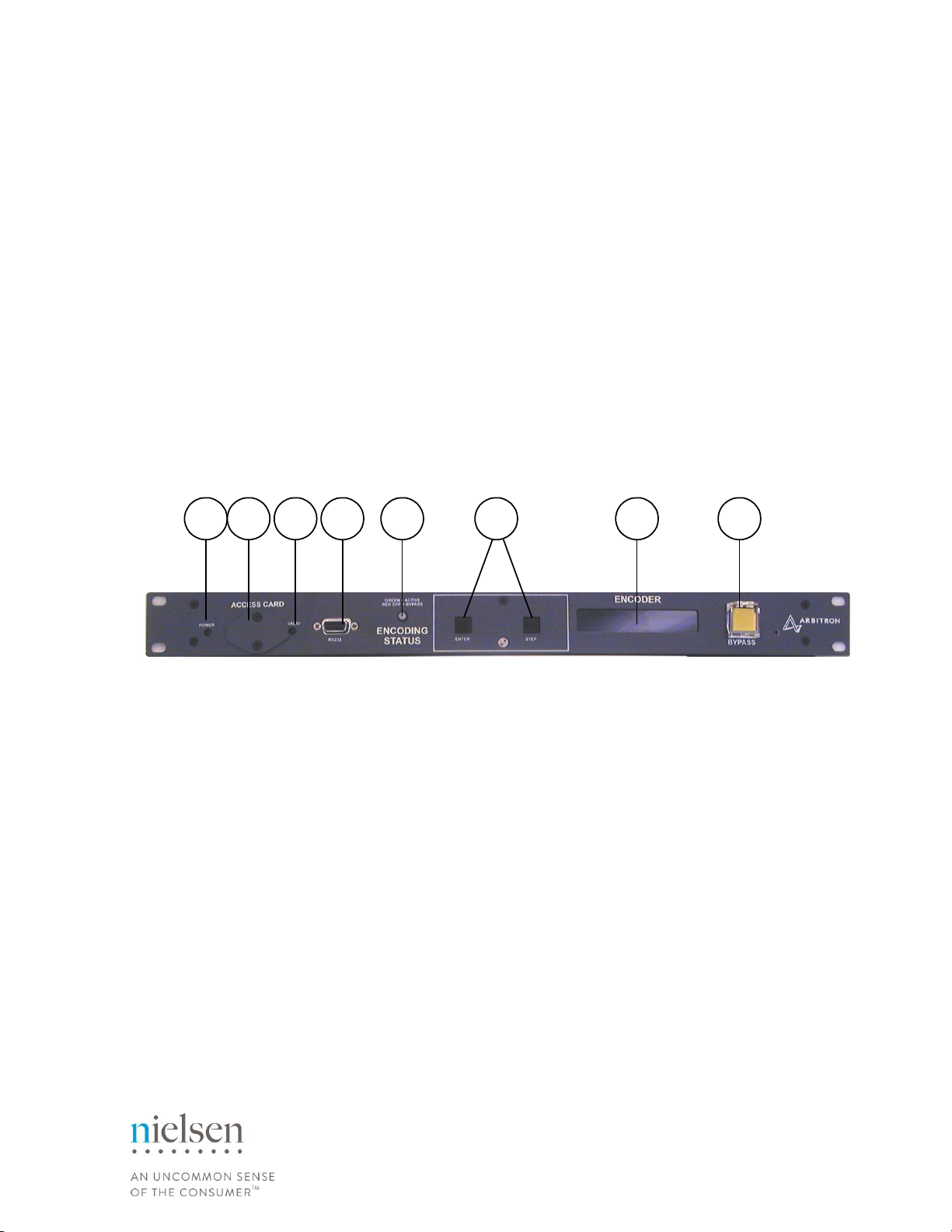
Figure 1: Front Panel of Nielsen Audio RoHS Compliant Digital SGE
The front panel of the SGE is pictured in Figure 1, and the front panel features are described below;
1. LED for power status
2. Smart Media Memory Card Interface dust cover. Behind this cover is the Smart Media
Memory Card Interface, which is used for software upgrades.
3. LED for Smart Media Status (Green indicates a valid card is detected)
4. Service Port
5. LED for Encoding Status
6. Two switch controls (primarily for LCD menu screen controls)
7. LCD (Displays operation status)
8. Enable/Bypass dual action push button
Equipment Manual: Encoder 1000-1161
Document #: 1050-1475
Revision: F
CONFIDENTIAL AND PROPRIETARY INFORMATION
Copyright © 2014 The Nielsen Company. All rights reserved.
12
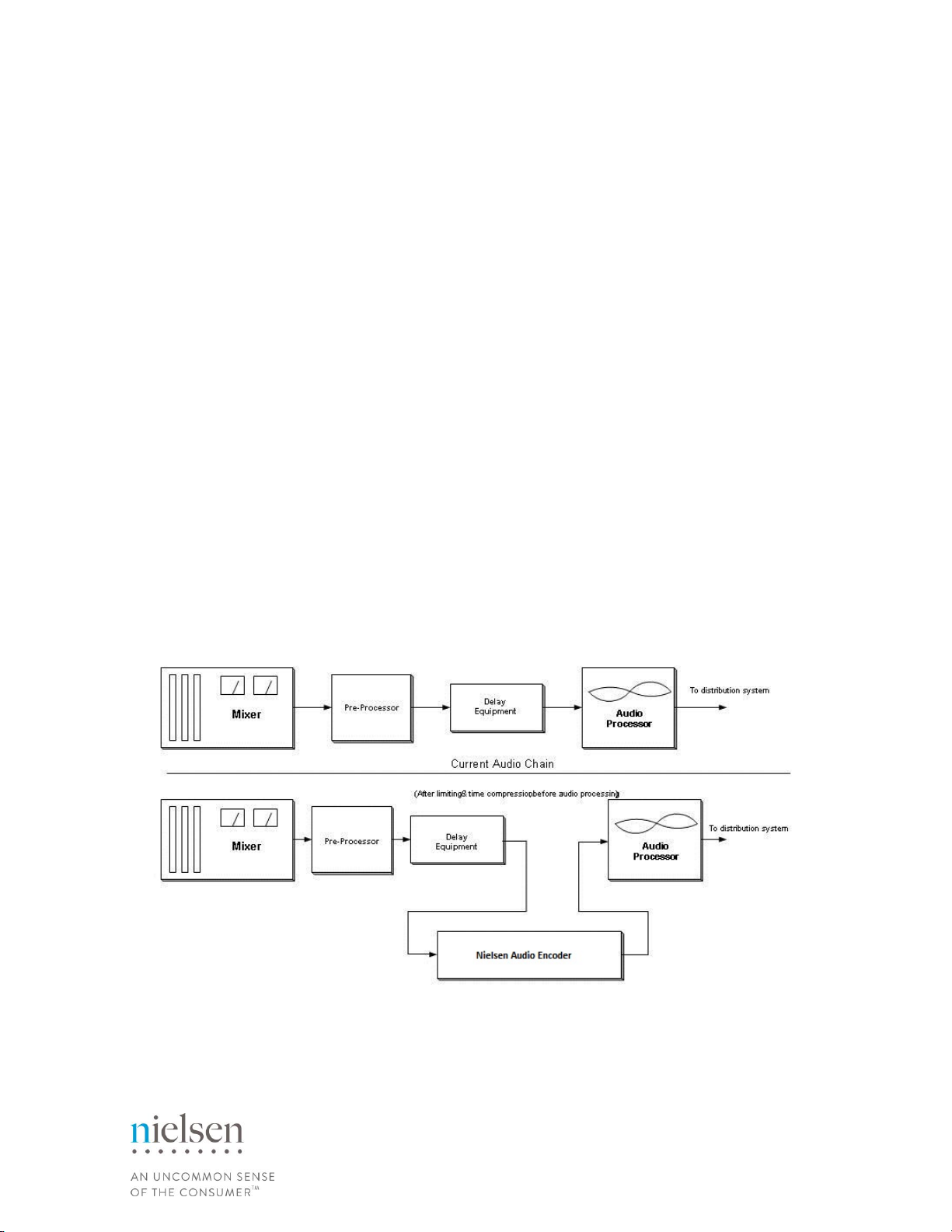
1.1. Suggested Placement in Audio Chain
Nielsen Audio has worked closely with numerous broadcast entities, including radio, TV and cable,
and has developed recommendations for the Encoder’s optimal operation within your audio chain.
Ultimately, however, decisions regarding placement of the Nielsen Audio Encoder within the audio
chain are the responsibility of each individual broadcast facility.
In AM radio stations, Nielsen Audio recommends that the Encoder is installed after the final audio
processor (i.e. Orban Optimod, Telos Systems’ Omnia, or others) to take advantage of the more
consistent audio leveling found at this point in the broadcast chain. In FM stations, Nielsen Audio
recommends that the Encoder be installed after a pre-processor and before the final audio processor
(i.e. Orban Optimod, Telos Systems’ Omnia, or others). This is because the Encoder cannot operate
on composite audio format output typical of stereo generators. When placing the Encoder after the
audio processor in the signal stream, you should be aware that the signal will undergo an increase in
amplitude roughly equal to 4% modulation. Figure 2 depicts an example of the Encoder placed in the
program audio chain.
The minimum average input level to the Encoder is -20 dBFS (ten percent of Full Scale).
Figure 2: Placement of Nielsen Audio SGE within the Audio Chain
Equipment Manual: Encoder 1000-1161
Document #: 1050-1475
Revision: F
CONFIDENTIAL AND PROPRIETARY INFORMATION
Copyright © 2014 The Nielsen Company. All rights reserved.
13
2. Installation
Follow these steps to add the SGE to your equipment chain. Throughout the installation process,
ensure that all plugs are firmly attached to their corresponding sockets.
1. Place the SGE into a 19” rack in an indoor climate controlled environment. Nielsen Audio
recommends allowing ½” of rack space above and below the Encoder to allow for adequate
ventilation and reduce the chances of overheating. DO NOT block or otherwise impede
airflow through the sides of the instrument.
2. Secure the SGE using screws in each of the four front panel corners.
3. Confirm that the Enable/Bypass push button on the front panel is in the ‘out’ position to put
the Encoder into bypass mode. (See Figure 1)
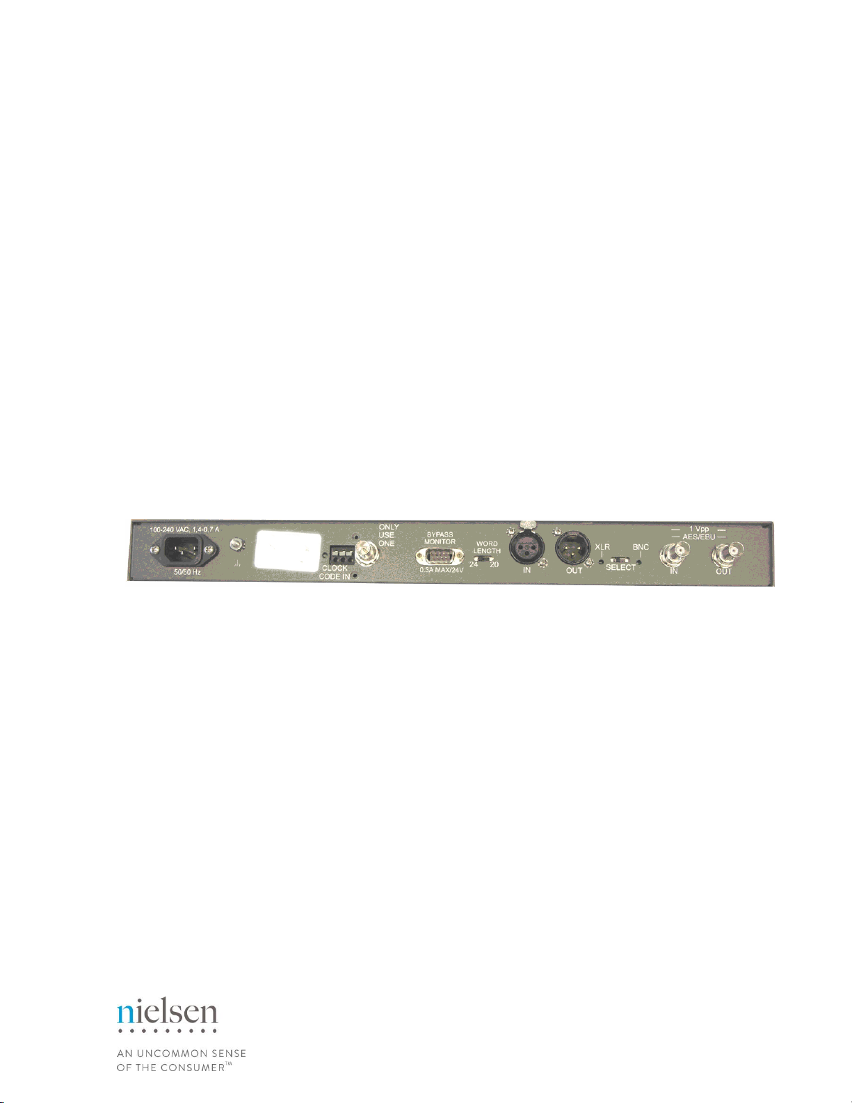
4. To use the balanced XLR connectors, slide the Select switch on the rear panel to XLR.
To use the unbalanced BNC connectors, slide the Select switch on the rear panel to BNC.
5. Balanced XLR inputs on the SGE are female; thus, the mating XLR cable is required to be
male. The gender for output connections is the reverse of input, as shown in Figure 3.
Figure 3: Rear Panel of Nielsen Audio RoHS Compliant Digital SGE
(with Time Decoder options installed)
Equipment Manual: Encoder 1000-1161
Document #: 1050-1475
Revision: F
CONFIDENTIAL AND PROPRIETARY INFORMATION
Copyright © 2014 The Nielsen Company. All rights reserved.
14
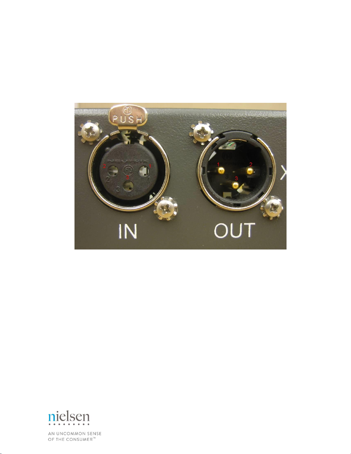
Balanced XLR pinouts for the Nielsen Audio SGE are as follows (See Figure 4):
Pin 1- Shell or ground
Pin 2- High
Pin 3- Low
Figure 4: XLR Connection Pinouts
Equipment Manual: Encoder 1000-1161
Document #: 1050-1475
Revision: F
CONFIDENTIAL AND PROPRIETARY INFORMATION
Copyright © 2014 The Nielsen Company. All rights reserved.
15
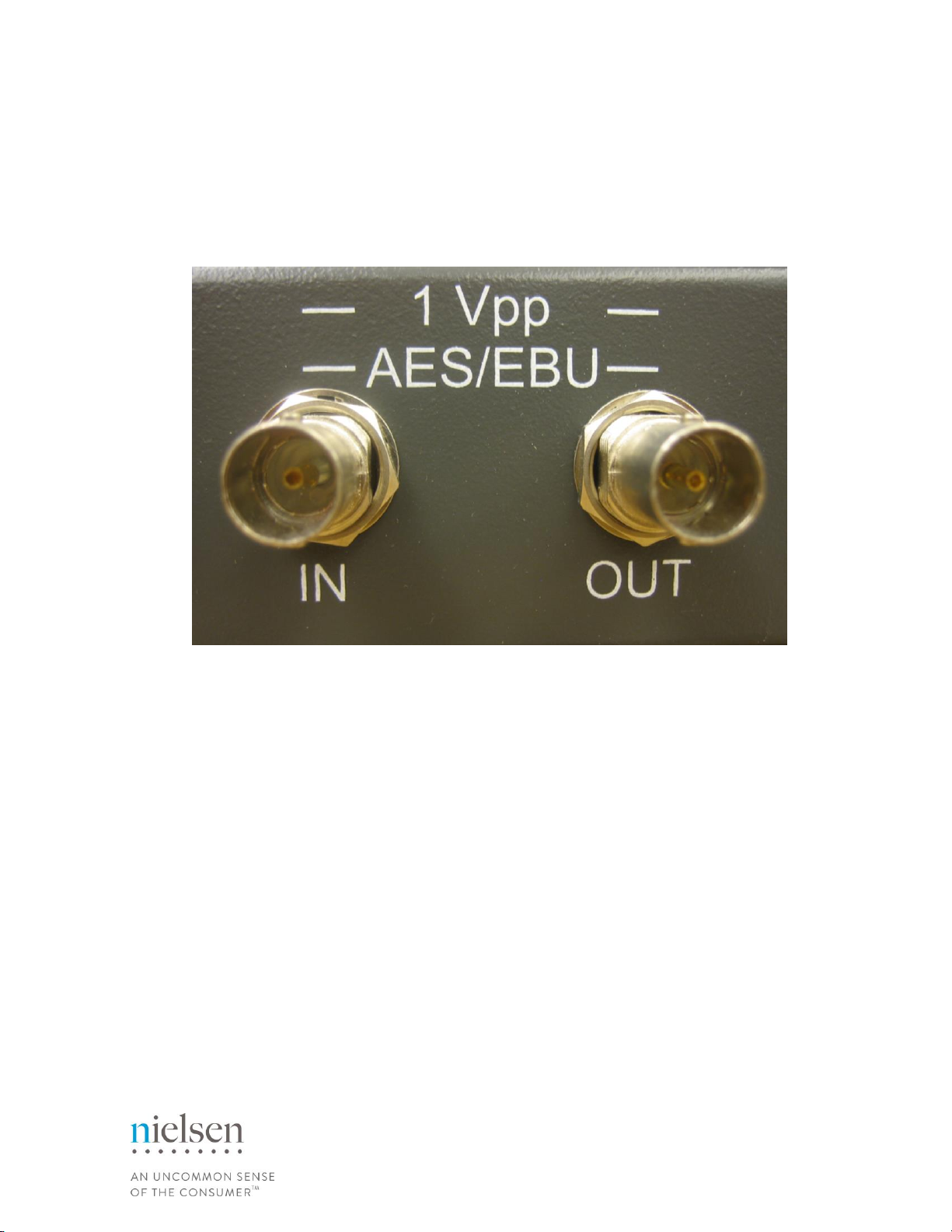
The unbalanced BNC connections, (input and output) are female BNC connectors, as shown in
Figure 5.
Figure 5: BNC Connectors
6. IF USING XLR: Connect the male end of an XLR cable to the connector marked IN on the
back of the SGE. Connect the female end of this same cable to the output connector on the
device currently outputting the program material to be encoded.
IF USING BNC: Connect the male end of a BNC cable to the BNC connector marked IN on
the back of the SGE. Connect the other end of this same cable to the output connector on the
device currently outputting the program material to be encoded.
7. IF USING XLR: Connect the female end of an XLR cable to the connector marked OUT on
the back of the SGE. Connect the male end of this same cable to the input connector on the
device to receive the encoded program material.
IF USING BNC: Connect the male end of a BNC cable to the BNC connector marked OUT on
the back of the SGE. Connect the other end of this same cable to the input connector on the
device to receive the encoded program material.
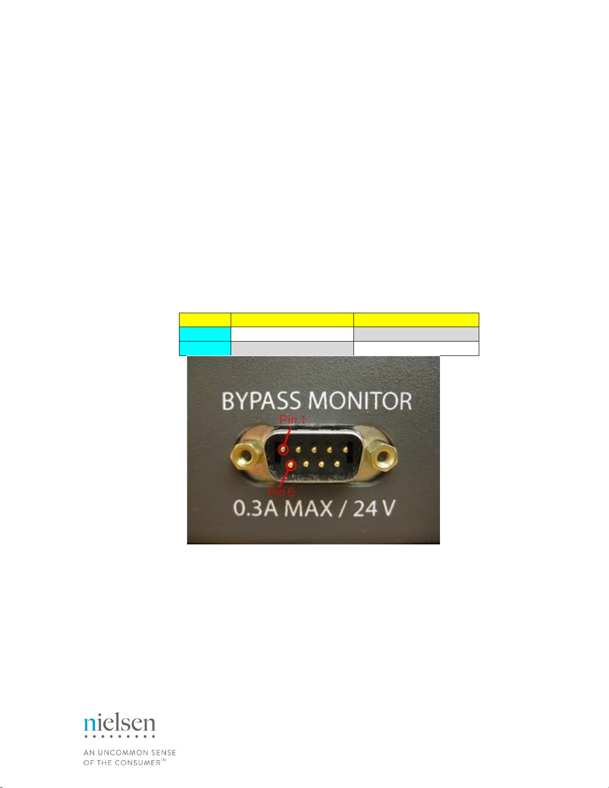
8. Optional: To allow remote monitoring of this Encoder’s bypass and encode modes, use a
DB9 cable to connect a remote bypass device to the male DB9 connector at the back of the
Encoder labeled BYPASS MONITOR. The pinouts on this connector are detailed below:
Pin 3 –Common connection
Pin 4 –Bypass mode (pins 3+4 shorted, 3+7 open)
Pin 7 –Encode mode (pins 3+7 shorted, 3+4 open)

Equipment Manual: Encoder 1000-1161
Document #: 1050-1475
Revision: F
CONFIDENTIAL AND PROPRIETARY INFORMATION
Copyright © 2014 The Nielsen Company. All rights reserved.
16
Table 1: DB9 Pinouts for Remote Monitoring of Encode/Bypass Status
Status = ENCODE
Status = BYPASS
Pin 4
Open to pin 3
Shorted to pin 3
Pin 7
Shorted to pin 3
Open to pin 3
Figure 6: DB9 Pinouts for Remote Bypass Monitoring
The pins are connected to an internal relay of the Encoder. The relay contacts are rated at 0.3A
max, 24VDC.
This outlet also provides access to a bypass mode remote control functionality and an alarm
status remote monitoring functionality. For more information on these features, see Section 3.3.4
and Section 3.4.
9. If the optional Time Decoder Input is enabled: To ensure that the Encoder will synchronize
to the station clock upon boot-up, one of the supported time code sources must be properly
connected to the SGE time code input. For more information, see Appendix “Using the
Optional Time Decoder Input.”
10. Connect the power cord to the SGE to the same plug strip that supplies power to the
instruments that will be connected to the input and output connectors of the SGE. The SGE
will turn on when power is supplied via the power cord.
11. The SGE is shipped with the Enable/Bypass push button on the front panel set in the ‘out’
position to put the Encoder into bypass mode. At initial power-on, the LCD will display
“Bypass Mode Encoder Disabled”. When in bypass mode, the Encoder does not encode
incoming signals, but allows them to pass through to the output unchanged. For more
information, see Section 3.3.2
12. To start encoding, see the instructions in Section 3.1

Equipment Manual: Encoder 1000-1161
Document #: 1050-1475
Revision: F
CONFIDENTIAL AND PROPRIETARY INFORMATION
Copyright © 2014 The Nielsen Company. All rights reserved.
17
3. Operations
3.1. Initiating Encoding
Once the Encoder is connected as described in Section 2, follow these instructions to begin
encoding:
1. Push the Enable/Bypass push button on the front panel to the ‘in’ position to enable Encoding
mode.
2. The LCD will then display “Encoding:” and a station specific message (station information).
3. The Encoding Status LED will display an unblinking green light to indicate normal operation,
and the relays will switch from bypass mode to encoding mode. An audible click may be
heard.
The SGE can be removed from the signal path and put into Bypass mode by pushing the
Enable/Bypass push button on the front panel to the ‘out’ position. This connects the input connectors
directly to their respective output connectors. See Section 3.3.2 for more information.
3.2. Immediately After Placing the Encoder On-Air
IMPORTANT: Before the installation of this Encoder is considered complete, Nielsen Audio requires
that a quality analysis check be performed on the encoded audio. The time required per Encoder is
minimal. Please call your Nielsen Audio contact to arrange this test.
3.3. Bypass Features
In bypass mode, signals input to the SGE pass through the device unchanged. The SGE provides
bypass modes for different circumstances as described in the three sections below.

Equipment Manual: Encoder 1000-1161
Document #: 1050-1475
Revision: F
CONFIDENTIAL AND PROPRIETARY INFORMATION
Copyright © 2014 The Nielsen Company. All rights reserved.
18
3.3.1. Power-Off Bypass
If there is no power applied to the SGE, an internal relay automatically routes the audio input
connectors directly to their respective output connectors, and all input signals pass through the SGE
unchanged.
3.3.2. Master Bypass
While the SGE is powered, pushing the front panel Bypass/Enable push button to the ‘out’ position
causes the SGE to bypass encoding. This effectively routes the audio input connectors to their
corresponding output connectors.
Certain software diagnostic fault detections (including a high temperature warning) can cause the unit
to place itself in bypass mode automatically. In this case, the LCD displays a message describing the
nature of the problem, and the Encoding Status LED on the front panel will change depending on the
nature of the problem.
When the SGE is in bypass mode with no errors, the Encoding Status LED on the front panel remains
dark, and the LCD displays “Bypass Mode Encoder Disabled.”
3.3.3. Bypass Mode Remote Monitor
In addition to providing status information via the front panel LCD display and encoding status LED
indicator, the Encoder provides a means to enable remote monitoring of its status. This is provided
via the DB9 connector on the rear panel of the Encoder. The 3-wire connection will allow another
device to monitor both bypass mode conditions (power off, Enable/Bypass push button position, error
condition) and encoding conditions (normal power-up, bypass mode, enable mode). See Step 8 in
Section 2 for pin-out information.
Equipment Manual: Encoder 1000-1161
Document #: 1050-1475
Revision: F
CONFIDENTIAL AND PROPRIETARY INFORMATION
Copyright © 2014 The Nielsen Company. All rights reserved.
19
3.3.4. Bypass Mode Remote Control
The Encoder provides the means to remotely control whether it is in bypass or enable mode. This is
provided via the DB9 connector on the rear panel labeled BYPASS MONITOR—the same connector
that provides the remote monitor capability. (See Step 8 in Section 2) To use this feature, connect a
5-20V DC positive terminal to pin 1 and a negative terminal to pin 6 of the rear panel DB9 connector.
Do not exceed 24V across pins 1 and 6.
The pinouts that support the bypass remote control are detailed below.
Table 2: DB9 Pinouts for Remote Control of Encode/Bypass Status
BYPASS
ENABLE
Pin 1
DC (5-20V) positive
DC (0 V) positive
Pin 6
DC negative
DC negative
Figure 7: DB9 Pinouts for Remote Bypass Control

Equipment Manual: Encoder 1000-1161
Document #: 1050-1475
Revision: F
CONFIDENTIAL AND PROPRIETARY INFORMATION
Copyright © 2014 The Nielsen Company. All rights reserved.
20
3.4. Alarm Status Remote Monitoring
The Encoder provides the means to remotely monitor its error status. This is provided via the DB9
connector on the rear panel labeled BYPASS MONITOR—the same connector that provides the
remote monitor capability. (See Step 8 in Section 2)
The pinouts that support remote alarm status monitoring are detailed below.
Table 3: DB9 Pinouts for Remote Monitoring of Alarm Status
Status = NORMAL
Status = ALARM
Pin 5
Open to pin 8
Shorted to pin 8
Pin 9
Shorted to pin 8
Open to pin 8
Figure 8: DB9 Pinouts for Remote Alarm Status Monitoring
Table of contents
Other Nielsen Media Converter manuals


