Norsat ATOM Ku GaN 20W BUC User manual

Operator Manual
ATOM Ku GaN 20/40/80W BUC&SSPA

© Norsat International Inc. (“Norsat”) All Rights Reserved
2021-09-02 052910 Rev E 2
Operator’s Manual
The information in this document has been fully reviewed and is believed to be entirely reliable. However,
Norsat International Inc., hereinafter referred to as Norsat, reserves the right to modify any products to
improve reliability, function, or design. Norsat does not assume any liability arising out of the application or
use of any product or circuit described herein. Norsat does not convey any license under its patent rights
or the rights of others.
Technical Support
This manual provides engineers with information necessary to operate the applicable system. Technical
support is available from Norsat.
Norsat International Inc.
Attn: Technical Support
110 –4020 Viking Way
Richmond, BC
Main: 1 (604) 821-2800
Support: 1 800 644 4562

© Norsat International Inc. (“Norsat”) All Rights Reserved
2021-09-02 052910 Rev E 3
TABLE OF CONTENTS
1.1 OVERVIEW.............................................................................................................. 5
1.2 FEATURES.............................................................................................................. 6
1.3 Cautions and Warnings............................................................................................ 7
2.1 Introduction .............................................................................................................. 8
2.2 J1 –IF/RF Inputs.....................................................................................................10
2.3 J2 –Monitor and Control Interface...........................................................................10
2.4 J3 –Ethernet Port ...................................................................................................13
2.5 Performing firmware update ....................................................................................14
2.6 J4 –DC Power........................................................................................................24
2.7 Serial Port Software Interface..................................................................................25
2.8 Ethernet Interface (ATOMControl™ Web Interface & ATOM SNMP Agent).............30
2.9 J5 –RF output.........................................................................................................36
2.10 Ground Connection..............................................................................................36
2.11 Fault Indicator / LED............................................................................................36
3.1 ATOM Installation....................................................................................................37
3.2 Fans & Baseplate Cooling.......................................................................................37
3.3 Accessories.............................................................................................................37
3.4 General Specifications.............................................................................................38
3.5 Standard Warranty..................................................................................................38

© Norsat International Inc. (“Norsat”) All Rights Reserved
2021-09-02 052910 Rev E 4
List of Figures
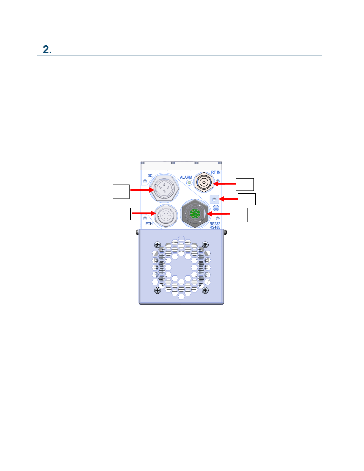
Figure 2-1: Input Connections for ATOM Ku GaN BUC Unit (N-Type Jack Shown).................... 8
Figure 2-2: Standard Waveguide WR75 Output for ATOM Ku GaN Unit.................................... 9
Figure 2-3: J2 M&C Connector Pin Arrangement......................................................................10
Figure 2-4: J3 Ethernet Connector Pin Arrangement.................................................................13
Figure 2-5: Tera Term Client for Firmware Image Upload .........................................................14
Figure 2-6: Configuring a New Kermit Target for Tera Term Client............................................15
Figure 2-7: Configuring Host, Port, and Service for Tera Term Client........................................15
Figure 2-8: Initiate Kermit File Send to the Target ATOM Device..............................................16
Figure 2-9: Selecting ATOM Firmware Image File for Upload to the Target ATOM Device........17
Figure 2-10: Kermit File Transfer in Progress............................................................................18
Figure 2-11: Firmware Version from ATOMControl FW Update Tab .........................................19
Figure 2-12: FW Image Browse Function..................................................................................19
Figure 2-13: Image File Selection Dialog...................................................................................20
Figure 2-14: Image File Confirmation and Start Update Function..............................................21
Figure 2-15: Progress Bar Indicates Firmware Update Progress...............................................22
Figure 2-16: Confirmation of Updated Firmware Version...........................................................23
Figure 2-17: DC Unit J4 Connector Pinout................................................................................24
Figure 2-18: Setup Serial Port...................................................................................................25
Figure 2-19: The Mute Logic Diagram.......................................................................................29
Figure A-1: 20-40-80W Ku GaN BUC/SSPA, Fan Cooled.........................................................39
Figure A-2: 20-40-80W Ku GaN BUC/SSPA, Baseplate Cooled ...............................................40
List of Tables
Table 1-1: Input and Outputs...................................................................................................... 6
Table 2-1: J2 Pinouts for ATOM Configurations........................................................................11
Table 2-2: ATOM Mute Control Behavior ..................................................................................11
Table 2-3: J3 Pinouts for Ethernet Port.....................................................................................13
Table 2-4: DC Unit J4 Connector Pinout ...................................................................................24
Table 2-5: Command Summary................................................................................................28
Table 3-1: General 20-40-80W ATOM Ku GaN Specifications..................................................38

© Norsat International Inc. (“Norsat”) All Rights Reserved
2021-09-02 052910 Rev E 5
Introduction
1.1 OVERVIEW
This operator’s manual applies to all ATOM SSPAs and BUCs with the following marketing numbers:
ATOMBKUGxxx (020/040/080W)
ATOMSKUGxxx (020/040/080W)
BUC - Block Up Converter and Amplifier
If this unit is a BUC, the IF input signal is upconverted to Ku-Band RF frequencies and then amplified to the
specified power.
SSPA –Solid State Power Amplifier
If this unit is a SSPA, the RF input signal is amplified to the specified power.

© Norsat International Inc. (“Norsat”) All Rights Reserved
2021-09-02 052910 Rev E 6
1.2 FEATURES
Inputs and Outputs
Table 1-1: Input and Outputs
20W / 40W / 80W
Input Type
Female N-Type Connector (BUC)
Output Type
Waveguide WR75 (Standard)
Waveguide WR62 (Wide Band Option)
Adaptors are available to convert output type to SMA, TNC, or N-Type connectors. Please
contact Norsat for more information.)
Electrical Interface
•M&C Connector –a ten-pin connector is used to interface with a host computer. See Section 2.3
J2 –Monitor and Control Interface for detailed description of the pinouts.
•Ethernet Connector –a six-pin connector is used to update the firmware and communicate with the
BUC/SSPA through the web-based ATOMControl interface. See Section 2.4 J3 –Ethernet port for
detailed description of pinouts.
•Power Connector –DC Units use a four-pin connector to provide power to the ATOM. See Section
2.6 J4 –DC Power for detailed description of pinouts.
•Ground Terminal –a #10-32 screw is used to ground the chassis during use.

© Norsat International Inc. (“Norsat”) All Rights Reserved
2021-09-02 052910 Rev E 7
1.3 Cautions and Warnings
W A R N I N G
Leakage Current
The ATOM may exhibit high leakage current during use. Ensure
that the ground terminal is grounded according to local
electrical codes prior to powering on the ATOM.
W A R N I N G
RF Radiation Hazard
The ATOM emits high power RF energy which is harmful to the
human body. Do not operate ATOM unless the RF output flange
is either terminated in an RF load (100W min) or connected to
the feed of a terminal.
Do not obstruct the RF output or feed output with any body part.
W A R N I N G
Do not allow equipment to be standing in water.
While the BUC/SSPA is designed to be used outdoors, the
equipment is not designed to operate in standing water. Failure
to follow this precaution could result in electric shock and injury
to persons.
C A U T I O N
Do not allow any items to fall into the unit from the waveguide
opening.
C A U T I O N
Apply voltage to the AC/DC input connector only as specified in
the original configuration of this unit. Application of a voltage
outside the specified range may cause the unit to become
damaged or non-functional.

© Norsat International Inc. (“Norsat”) All Rights Reserved
2021-09-02 052910 Rev E 8
Interface Control
2.1 Introduction
The unit has four connectors on the input side of the housing and one waveguide port on the output side.
The interface for these connectors is detailed in this document.
On the input side, there are the following connectors:
•J1 –IF or RF Input; N-Type Jack
•J2 –Ten-pin circular shell size 12 Amphenol connector for M&C (RS232/RS485)
•J3 –Six-pin circular shell size 10 Amphenol connector for Ethernet
•J4 –Four-pin circular shell size 12 Amphenol DC power connector
•J6 –Ground terminal
Figure 2-1: Input Connections for ATOM Ku GaN BUC Unit
(N-Type Jack Shown)
J2
J1
J3
J4
J6

© Norsat International Inc. (“Norsat”) All Rights Reserved
2021-09-02 052910 Rev E 9
On the output side, there is one connector:
•J5 –WR75 waveguide RF output
•J5 Option: WR62 waveguide RF output for wide band
J5
Figure 2-2: Standard Waveguide WR75 Output for ATOM Ku GaN Unit

© Norsat International Inc. (“Norsat”) All Rights Reserved
2021-09-02 052910 Rev E 10
2.2 J1 –IF/RF Inputs
BUC
The IF input is a 50 ohm type-N connector. The input is to be applied here (950-1700 MHz for Extended
Band; 950-1450 MHz for Standard Band). Also, the 10 MHz signal input is diplexed onto this line. Therefore,
the IF signal and 10 MHz reference are both traveling on this line. The connector is DC-blocked. Do not
exceed +/- 50VDC on this port.
The 10-MHz signal should be accurate within +/- 1ppm, otherwise the BUC may have difficulty phase
locking to it. The 10-MHz should be free of sideband spurs, particularly close-in (under 100 kHz), as these
may also cause failure to lock. Power level of the 10 MHz reference signal should be +/-5 dBm.
SSPA
In the SSPA-only configuration, this is the RF input. It is a precision type-N connector, with performance to
18GHz. No 10 MHz reference is required for SSPA-only operation.
2.3 J2 –Monitor and Control Interface
The M&C interface is used to control the unit with a host computer. All on-board sensors are accessed
through this interface. Use of this connection is optional. Each ATOM is supplied with a mating connector
for the M&C interface.
Monitor and Control Interface Pinout
The M&C interface is a ten-pin miniature circular connector. This connector is a MIL-C-26482 Series 1
receptacle, shell size 12, 10 pin (Amphenol® part number 93-533723-10P). A mating connector is
Amphenol® part number PT06E-12-10S-476. A range of compatible part numbers for the mating connector
may be used to add options to the plug such as right-angle, stress relief clamp, metal color/finish, etc.
Please contact the connector manufacturer for more information and/or refer to Amphenol® catalog 12-
070.
Figure 2-3: J2 M&C Connector Pin Arrangement

© Norsat International Inc. (“Norsat”) All Rights Reserved
2021-09-02 052910 Rev E 11
Table 2-1 summarizes the various pinout for the 20-40-80W ATOM Ku GaN.
Table 2-1: J2 Pinouts for ATOM Configurations
Connector
Pin
Standard
Configuration
Connector
Pin
Standard
Configuration
A
RS-485 Rx-
F
RS-232 Rx
B
RS-485 Rx+
G
GND
C
RS-485 Tx+
H
Open
D
Mute
J
RS-485 Tx-
E
RS-232 Tx
K
Open
Ground Pin(s): Pin G
Ground/shield for Ethernet, RS-485, RS-232 & Mute signals. This is internally connected to the case
ground. Do not exceed 100mA.
Mute Control: Pin D
This pin controls the hardware mute state of the ATOM. When muted, the power transistors are turned off,
reducing power consumption and providing an RF output noise close to the thermal noise floor.
The operation of this pin is fully configurable through the M&C Interface. Pin D can be biased with either
an internal Pull-Down (to 0V) or an internal Pull-Up (to 4V). Pin D is also configurable to be either active
high (3-5V on Pin D will mute the unit) or active low (0-0.8V on Pin D will mute the unit). All voltages are
relative to Pin G or the Case Ground.
Because of the configurable pull-down / pull-up resistor, the unit can be configured to be active (i.e. not
muted) when Pin D is left floating. Therefore, it is possible to operate the unit with no connection pin D.
The ATOM mute control behavior is shown below in Table 2-2. Note that the ATOM may be factory ordered
with alternate configurations, so the Default configuration shown in the table is not reflective of all ATOM
units. Table 2-2: ATOM Mute Control Behavior
Configuration
Mute Line
Polarity
Mute Line
Bias
Sample
Input 1
Sample Mute
State 1
Sample
Input 2
Sample Mute
State 2
Sample
Input 3
Sample Mute
State 3
Default
0V = Unmute
Pull-Down
0V
Unmuted
5V
Muted
Floating
Unmuted
Sample 1
0V = Unmute
Pull-Up
0V
Unmuted
5V
Muted
Floating
Muted
Sample 2
5V = Unmute
Pull-Down
0V
Muted
5V
Unmuted
Floating
Muted
Sample 3
5V = Unmute
Pull-Up
0V
Muted
5V
Unmuted
Floating
Unmuted
Note that the ATOM mute state can also be controlled through the M&C interface. The software
mute setting takes priority over the hardware pin. Refer to Section 2.7 for details.

© Norsat International Inc. (“Norsat”) All Rights Reserved
2021-09-02 052910 Rev E 12
RS-485 Port: Pins A, B, C, J, G
These five pins form a standard four-wire RS-485 serial port, with Rx+, Rx-, Tx+, Tx-, and serial port ground.
Since communication with the ATOM is only half duplex, it is possible to deploy the ATOM on a two-wire
RS-485 network by connecting the Tx+ & Rx+ and Tx- & Rx- wires together.
Tx+ and Tx- are the differential pair which carries a signal from the host computer to the unit. Rx+ and Rx-
are the differential pair which carries a signal from the unit to the host computer. Connect these to the host
computer RS-485 port accordingly.
RS-232 Port: Pins E, F, & G
These pins form a standard RS-232 serial port. Pin F carries a signal from the host computer to the unit
and Pin E carries a signal from the unit to the host computer. Pin G must be connected to the ground pin
on the host computer.

© Norsat International Inc. (“Norsat”) All Rights Reserved
2021-09-02 052910 Rev E 13
2.4 J3 –Ethernet Port
ETHERNET PORT PINOUT
The Ethernet port is a six-pin circular connector. The connector is a MIL-C-26482 Series1 receptable, shell
size 10, 6 pin (Amphenol® part number 93-533722-06P). A mating connector is Amphenol® part number
PT06E-10-6S-476. A range of compatible part numbers for the mating connector may be used to add
options to the plug such as right-angle, stress relief clamp, metal color/finish, etc. Please contact the
connector manufacturer for more information and/or refer to Amphenol® catalog 12-070.
Figure 2-4: J3 Ethernet Connector Pin Arrangement
Table 2-3: J3 Pinouts for Ethernet Port
Connector Pin
Standard Configuration
A
Ethernet Tx-
B
Ethernet Tx+
C
Open
D
Ethernet Rx+
E
Ground
F
Ethernet Rx-

© Norsat International Inc. (“Norsat”) All Rights Reserved
2021-09-02 052910 Rev E 14
2.5 Performing firmware update
Performing firmware update using Kermit client by Ethernet interface is recommended for firmware versions
2.0.0 or later. For firmware versions older than 2.0.0, use serial port connection with ATOMControl
software.
ATOMControl is a program designed for monitoring and controlling Norsat’s ATOM Series of BUCs and
SSPAs. This software and user manual are available on the Norsat ATOM Series website.
Caution: Always back up the settings of the BUC or SSPA before updating firmware using the latest
version of ATOMControl software. Refer to ATOMControl User Manual for how to back up and restore
device settings to and from an ATOM configuration file.
Firmware Update Using Kermit Client by Ethernet
Firmware version 2.0.0 and later running on the BUC or SSPA support firmware update by Ethernet
interface using Kermit client software. Tera Term and HyperTerminal are recommended as clients for
updating firmware on the BUC or SSPA.
The following illustrates how to configure Tera Term for firmware image upload. Configuring and operating
other Kermit clients are similar.
Figure 2-5: Tera Term Client for Firmware Image Upload

© Norsat International Inc. (“Norsat”) All Rights Reserved
2021-09-02 052910 Rev E 15
Run the Tera Term software. Select New Connection from the menu to configure the target for uploading
files.
Figure 2-6: Configuring a New Kermit Target for Tera Term Client
The New Connection dialog appears. Select TCP/IP, fill in Host IP and TCP Port# as 1649, and select Other
for Service. Proceed with OK.
Figure 2-7: Configuring Host, Port, and Service for Tera Term Client

© Norsat International Inc. (“Norsat”) All Rights Reserved
2021-09-02 052910 Rev E 16
Tera Term is now ready for transferring firmware file to the BUC or SSPA. In the menu, select Transfer,
Kermit and Send.
Figure 2-8: Initiate Kermit File Send to the Target ATOM Device
A file selection dialog appears. Locate an official version of ATOM firmware image file. Official ATOM
firmware image file name has the format ATOM_KUGAN_FW_APPL_<version>.fwa.
Caution! Uploading a file that is not an official ATOM firmware image will render the ATOM device
inoperable on power cycle! Ensure to select an official ATOM firmware image file with <.fwa>
extension before sending. Always select an image file for a newer version of ATOM firmware.
Contact customer service if you wish to downgrade firmware version.

© Norsat International Inc. (“Norsat”) All Rights Reserved
2021-09-02 052910 Rev E 17
Figure 2-9: Selecting ATOM Firmware Image File for Upload to the Target ATOM Device
Select the Open or Send button. Tera Term will proceed with the firmware image upload to the ATOM
device.

© Norsat International Inc. (“Norsat”) All Rights Reserved
2021-09-02 052910 Rev E 18
Figure 2-10: Kermit File Transfer in Progress
The transfer dialog closes when the transfer has completed. Power cycle the BUC or SSPA and wait 10
seconds for the new firmware to initiate and start. Verify the firmware version and restore the device
setting using the latest version of ATOMControl software.

© Norsat International Inc. (“Norsat”) All Rights Reserved
2021-09-02 052910 Rev E 19
Firmware Update Using ATOMControl by Serial Port
When supported by the firmware on the BUC or SSPA, through the M&C interface or Ethernet port, the FW
update tab contains controls for performing a firmware update. All the firmware versions will be displayed
once the BUC is communicated with ATOMControl and being initialized.
Figure 2-11: Firmware Version from ATOMControl FW Update Tab
Click the Browse button to show the find the Image File Selection Dialog.
Figure 2-12: FW Image Browse Function

© Norsat International Inc. (“Norsat”) All Rights Reserved
2021-09-02 052910 Rev E 20
Select the firmware image file from the Image File Selection Dialog for updating on the ATOM Ku GaN
device. Click Open to confirm the selection.
Figure 2-13: Image File Selection Dialog
This manual suits for next models
5
Table of contents
Other Norsat Media Converter manuals