NIEWIADOW Predom 126 D Guide
T H E C A R A V A N P R E D O M
DESIGNS & MANUAL FOR USE
P r e d o m 126 D / E / ET
P r e d o m 126 N / NT / NTL
Fabr ka Prz czep
NIEWIADOW Sp.z.o.o.
Poland
97-225 Ujazd
tel. +48 44 719 20 00
fax. +48 44 719 21 61

CONTENTS.
1. Technical data
2. Towing car for preparation for caravanning
3. Function and service
3.1. Ball tow hook
3.2. Braking s stem
3.3. Folded support
3.4. Wiring s stem 12 V
3.5. Wiring s stem 220 V AC
3.6. Gas s stem
3.7. Water piping s stem
3.8. T res
4. The caravan to use
4.1. Load arrangement and protection
4.2. Caravan preparation for a night rest
4.3. Natural ventilation
5. Recommended activities and handling before departure
6. Chassis maintenance
7. Care and small repairs
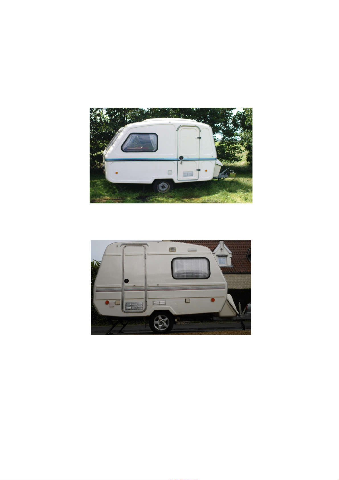
Dear Customer – Buying our Design N-126d or N-126e – you have gained an advantage of famous
caravan. Familiarity with this manual will ma e you enjoy your caravan and its outstanding properties
as well as will give you satisfaction and nowledge about properly use of all offered functions.
Thoroughly reading, understanding and following up all instructions of the manual allows you properly
and easy maintenance and to avoid surprises and unnecessary repairs. We are hopeful that this
purchase will give you a lot of happy hours. We wish you ' Good luc ' and wonderful leisure time.
“ Predom – Prespol “
1. Technical date.
N126d N126e
Total length 3900 mm 3900 mm
Total width 1940 mm 1940 mm
Total height 2180 mm 2180 mm
The construction and living space – length 2700 mm 2700 mm
– width 1840 mm 1840 mm
– height 1850 mm 1850 mm
Wheel trac 1500 mm 1500 mm
Sleeping places 2 + 1 2 + 2
Sleeping place dimension – front 1840 x 560 mm 1480 x 930 mm
– bac 1840 x 1210 mm 1810 x 1210 mm
Dead weight of the caravan 550 g 550 g
Allowed useful load 100 g 100 g
Ball diameter 50 mm 50 mm
Vertical load of the coupler 35-45 daN 35-45 daN
2. Towing car preparation for caravanning.
The car prepared to travel with a trailer towed should be equipped with properly coupler (tow hoo ),
two properly extended rear views and two electricity connectors. Ball diameter of the tow hoo is
50 mm and the distance between the centre of the tow ball and the ground will be between 350 and
450 mm. Both electricity connectors are seven polar 12 V plug-in soc ets. Signalling electricity
connection soc ets should be in accordance with the standard ISO 1724-1980 and connection soc et
for living space lighting should be in accordance with the standard ISO 3732-1976.
3. Function and service.
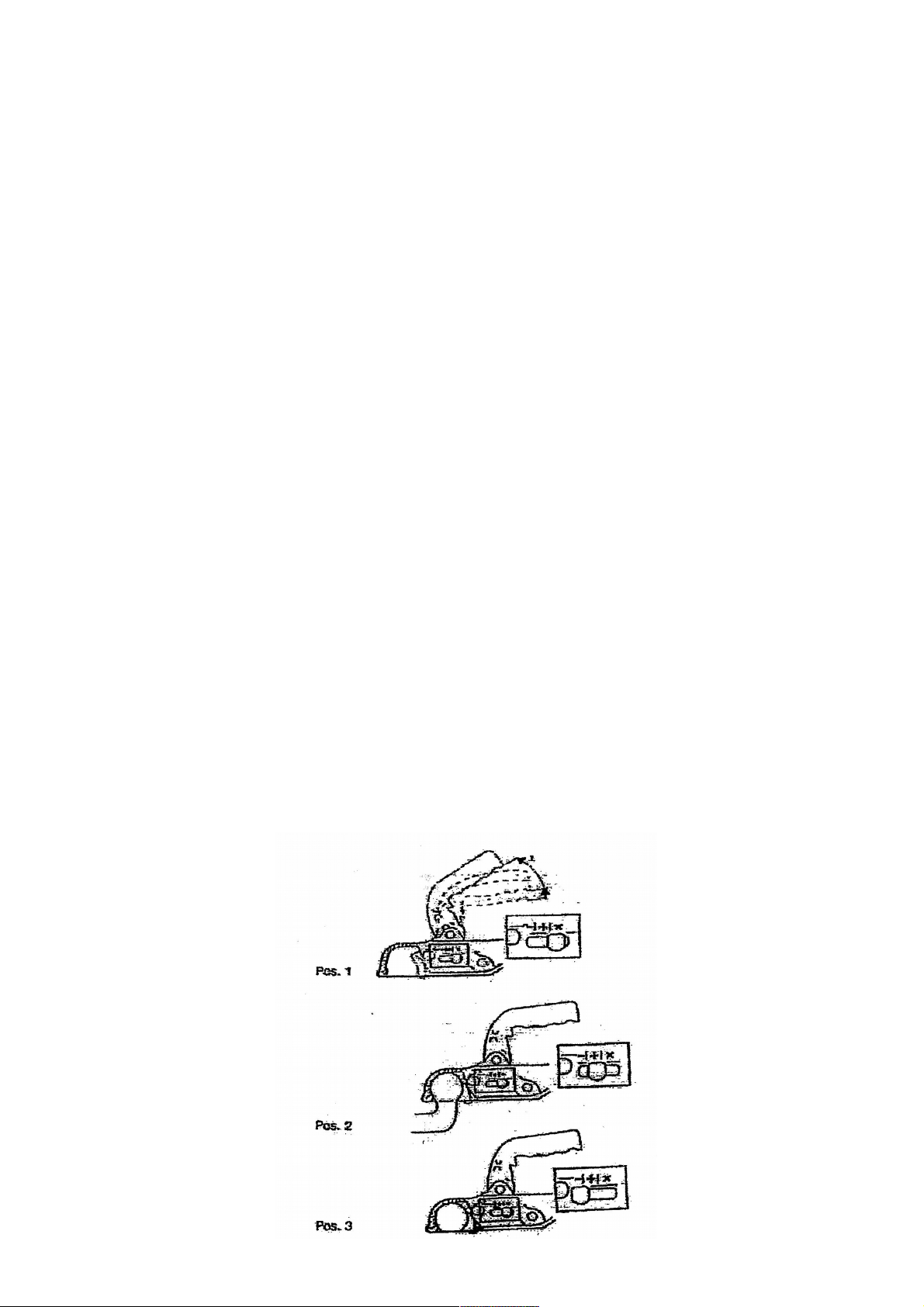
3.1. Ball tow hook.
Preparation: the lever (1) put up and point it towards front side (2)
Chec ing the clamping safety – using the safety indicator:
– the coupler is right and firmly connected when the indicator is located within the field “+”
– the coupler is wrong connected or partly worn out when the indicator is within the field “-”
– the worn out coupler should be changed immediately
Figure 1 : The lever

3.2. Braking s stem.
The caravan is equipped with an overrunning bra e which is automatically out of operation during the
car travelling bac . There is an additional hand operated bra e effective with both travel directions.
Bra e adjustment (see fig.2 and 3).
Bra e system adjustment range includes the gap between bra e shoes and a drum adjustment as well
as actuating rod adjustment.
Activities with the gap between the bra e shoes and the drum adjustment (see fig.2):
– till the caravan up unreel the wheels free rotation ability
– chec the bra e actuating line which should be hanged down freely, if not, decrease its tension
– remove a covering cap of the gap adjustment system protection
– using a screw-driver turn the pin on until you reach the drum rotation bloc age in forwarding direction
– turn the pin on in reverse direction until you reach the drum free rotation without any friction
Figure 2 : The gap between bra e shoes and drum adjustment.
Turning the pin on according an arrow which is mar ed on a brac et, effects in decreased gap between
the bra e shoes and the drum. Adjustment of actuating rod follows usually the successful adjustment
of the gap between the bra es shoes and the drum.
There is following action operated lever of the bra e:
– loose the manual operated lever of the bra e
– chec tension of the bra e actuating line and adjust it at stable adjusted transition, in this purpose,
turn the adjusting nuts (6) and (7), located on the line end (4), until you reach a right angle between
a cross piece (5) and an actuating rod (1)
– adjust on overrunning device (detail A fig.3) both nuts (3) of the actuating rod (1) until you reach the
gap of 1 mm between front surface of the nut and a thrust plate of the spring, located in the cylinder
inside.
Under properly bra e and with hand lever pointed on the second step of the ratchet, both wheels
should be bra ed with the same sensed moderate force. With loose handler completely the wheels
must be rotated freely without notice resistant.
Figure 3 : Overrunning bra e.

Trouble of the bra e system and its remedies:
Malfunctioned or insufficient bra ing force:
1. Adjust the wheels bra e or actuating rod
2. Chec bra e shoes, change them if worn
3. Clean or changed oiled or fatted bra e lining
4. Remove from the bra e lining residual dirtied, ex. Dust
5. Chec properly function of the overrunning device, lubricate its moving elements
if necessary
Trailer bra es itself during accelerator release:
1. Change damaged or worn the damping spring of the overrunning device
Bra ing force difference between right and left wheel:
1. Adjust the bra e shoes according to earlier described procedure
2. Chec condition of the bra e actuating line, lubricate or change if necessary
3. Chec right angle between the actuating rod and a cross piece of the overrunning-
device
4. Chec condition of the bra e shoes lining, clean or change it if necessary
Jammed trailer bra ing:
1. Adjust the gap of the bra e shoes and set the actuating rod position
2. Chec properly function of the overrunning device, the actuating rod and movable
connections, lubricate them if necessary
3. Chec damper condition of the overrunning device, change it if necessary
Bra e drums heating:
1. Adjust the bra e
2. Chec the bra e actuating fine, lubricate or change it if necessary
3. Chec damper condition of the overrunning
4. Chec the return lever and its flexibility, clean and smear it if necessary
3.3. Folded support.
The main tas of the folded support is to eep the caravan in its horizontal position during par ing of
camping. Small heigh differences in cross direction are levelled by floor lifting, using shims under
wheels and folded supporting legs. In case of unstable ground ex. Erratic soil, is recommended to
found every paw of the folded supporting legs with shims ex. With bric s or pieces of wood. Folding
or erection of the supporting legs required some effort. To ma e this easy and to maintain the support
in reliable condition put a couple drops of machine or gear oil into the side bearing on every spindle
of the supporting legs.
3.4. Wiring s stem 12 V.
The wiring system of the caravan consists of two separate wo nets: one for outside signalling lamps
of the towed vehicle and other for caravan living space lighting. Power supply is transmitted through
two different seven polar 12 V plug-in soc ets.
Signalling s stem.
Diagram of this system for the caravan Designs N126d and N126e is shown on the fig.4. The wires
connection terminals within plug-in soc et (12N) are in accordance with the standard ISO 1724-1980
L turn signal left z yellow
•fog light n blue
31 vehicle mass b white
R turn signal right t green
58R rear right + number plate light o brown
54 stoplight red
58L rear left c blac

Diagram ey: 1 connection plug-in soc et
2 front position lamp
3 left rear
4 right rear
5 number plate light
6 fog light
Figure 4 : Diagram of signalling light system 12 V of the caravan N-126d & N-126e
Caravan inside wiring s stem 12 V.
Diagram of the caravan living space lighting wiring system for Design N-126d is shown on the fig.5 and
for the N-126e on the fig.6. The system is designed to wor with a transformer 220V/12V.
To connect on the transformer to power-net, carry out following activities :
– disconnect the plug-in soc et connection out of the driving car
– connect the transformer with 220 V AC soc et, located next to the left bed, connect the plug of the
transformer with the 12 V soc et (8) of the caravan living space lighting, located next to the left bed
The net is protected with a fuse of 6,3 A, located under a cover of the 12 V wires bundle next to the left
fore bed. The 12 V plug-in soc et allows connection the 12 V electric equipment to the net. The wiring
connection terminals in the plug-in soc et are in accordance with the standard ISO 3732-1976.
Bulbs list of the caravan: inside lighting → tube shaped lamp 12V/5W
number lighting → bayonet soc et bulb 12V/5W
flashing light → bayonet soc et bulb 12V/10W
fog signalling light → bayonet soc et light 12V/21W
stop-rear standstill-front standstill light → bayonet soc et bulb 12V/5W
Figure 5 : Diagram of the caravan living space lighting system 12 V for design N-126d
10 vehicle mass b white
11 power supply red
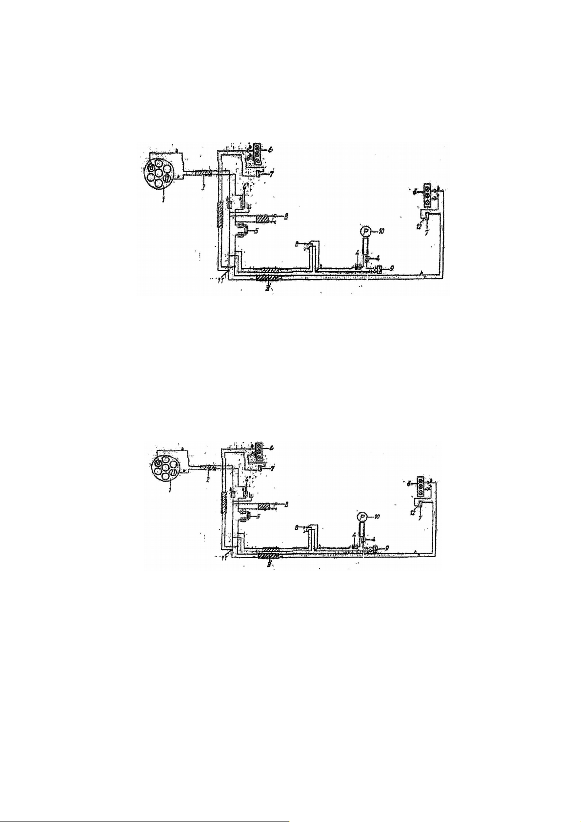
Diagram ey : 1 Connection plug-in soc et 12V 7 Lighting switch
2 Inside led bushing 8 Soc et 12 V, 10 A, type 47 K
3 Wires bundle 9 Water pump switch
4 Plug-in connector 10 Waterpump
5 Fuse with holder 11 Integrated connector
6 Living space lighting 12 Terminal
Figure 6 : Diagram of the caravan living space lighting system 12 V for design N-126e.
10 vehicle mass b white
11 power supply red
Diagram ey : 1 Connection plug-in soc et 12 V 7 Lighting switch
2 Inside led bushing 8 Soc et 12 V, 10 A, type 47 K
3 Wires bundle 9 Water pump switch
4 Plug-in connector 10 Water pump
5 Fuse with holder 11 Integrated connector
6 Living space lighting 12 Terminal
3.5. Wiring s stem 220 V AC.
This system is designed for use the electricity power with voltage of 220 V AC and is suitable for
supply the equipment with the same voltage.
Diagram of the wire system 220 V AC is shown on fig. 7. Connection with power source is made with
25 meter cable (1) supplied with the caravan. Connect outdoor soc et (2) of the caravan with
available electricity 220 V AC source, located near the caravan. The double soc et (5) is assigned
as a power source for refrigerator and transformer 220V/12V. The single soc et (4) gives a possibility
to use additional equipment with maximal power requirement of 1500 watt.
1 Connecting cable 25 meter 4 Single soc et indoor
2 Soc et outdoor 5 Double soc et indoor
3 Current differential protection
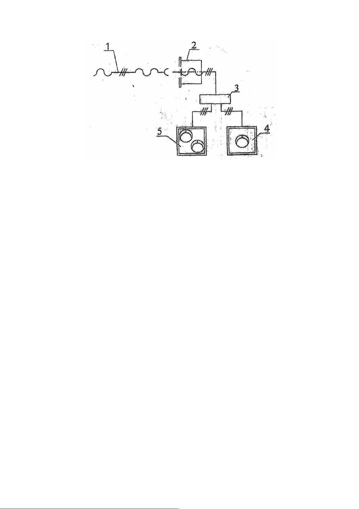
Figure 7 : Diagram of the wiring system 220 V AC.
3.6. Gas s stem
Built-in coo er plate is designed for gas propane or butane under pressure range of 3000-4000 N/m².
Depending on a gassytem, the coo er plate can be equipped with distribution valve for a cooling box
connection. The distribution valve, if exists, is located inside the itchen cupboard. The caravan
should be equipped with a gas bottle and its pressure reducing valve, suitable to gas pressure of used
coo er. The gas bottle compartment is suitable for two bottles each with a capacity of 2 or 5 ilograms
of gas.
In order to properly using the gas system, carry out following activities :
– screw on the pressure reducing valve on the gas bottle, until the fassteningnut reaches its properly
tightness
– put on the bottle into its compartment
– safe the bottle against suddenly and unnecessary movements in the compartment, using clamps and
flexible fastenings-belts
– put on the flexible hose on the nipple of the reducing valve and fit it with a clamping-ring
– open the valve of the bottle, the distribution valve, if any, choose the gas stream towards the coo er
– ignite the burner, it should be burn with a blue-violet coloured flame and a distinct core
If coo er is equipped with a flame safety device, carry out following activities :
– press the setting hand-wheel and turn it on the maximal flame position
– ignite the burner until to the maximal flame
– hold the hand-wheel pressed for 15 seconds
– set require flame intensity
– try again, when flame has extinguished.
Chec condition of the rubber hose regular and change it if the hose is damaged.
Notice that properly use of the coo er as well as reliable and properly condition of entire gas system
is effecting directly in safety use of the entire caravan.
Thus, on this reason, following is forbidden strictly :
– connecting any gas fed equipment without the gas pressure reducing valve to the bottle directly
– to use any lea y gas fed equipment for lea y gas distribution system
– opening the feeding valve of the cooling box when the box is lea y or opened
– mending or lingering on the gas distribution system or on the gas fed equipment to repair it yourself
– heating with the coo er flame the caravan living space
– to use the coo er by closed vent holes or bloc ed vent system of the caravan living space
– exchange burner nozzles yourself
– to use movable heaters fed on gas
In case of fire : – evacuate all persons out of the caravan
– close the main valve of the bottle and remove it out of the caravan
– fight the fire using the board extinguisher (available as a car obligatory equipment)
– call the fire brigade
Suitable for this caravan purpose is the universal powder extinguisher.
3.7. Water piping s stem.
The water piping system includes : – one tan (container) with capacity of 10 litres
– an electric driven water pump
– a water valve
– a water valve, actuated with pedal
The tan is located inside the cupboard. The pedal valve is located over the left wheel. Before a long
time still stand or before cold season empty the water tan and water piping completely. There is
special space inside the gas bottle compartment, designed for two water tan s. Before caravan
departure, fasten the water tan s protecting them against suddenly and unnecessary movements.
Put down a container under waste water drain.
3.8.T res.
Size : 155 R 13
Pressure : dead/under load = 160 / 190 Pa
To ensure a long time tyres us :
– chec air pressure regularly
– don't bra e suddenly without serious reason
– even with a short time the caravan using, support up with folded supporting legs
– during the cold season support up the caravan with legs and reduce the air pressure
For a wheel removing, support up the caravan with the rear supporting legs and drop the pulling shalt
of the vehicle on the ground surface. Loose the wheel fastening bolts. Lift de pulling shaft together
with entire caravan, using its small support wheel, designed for this purpose, until you reach free
rotation of the travelling wheels. Unscrew the wheel fastening bolts and remove the wheel. Fasten
the wheel again in reverse sequence.
4. The caravan to use.
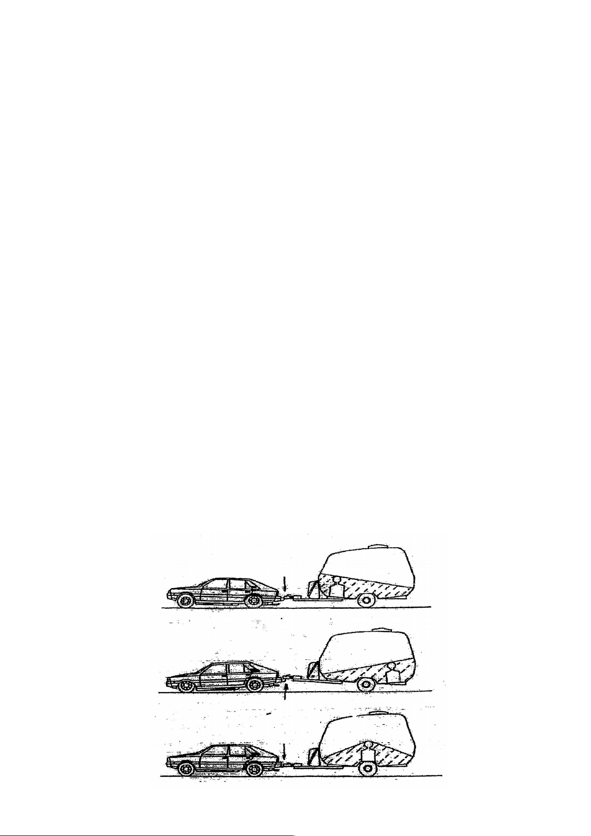
4.1. Load arrangement and protection.
The load, located inside the caravan living space should be arranged uniformly to reach uniform both
wheels loading. Safe and protect the heavy and fragile things against suddenly displacements during
caravan towing. Position in front of rear within the caravan cabin any extremely heavy load is not
allowed. These load should be positioned over the axle. Loo on fig. 8 : the last position is allowed.
Figure 8 :
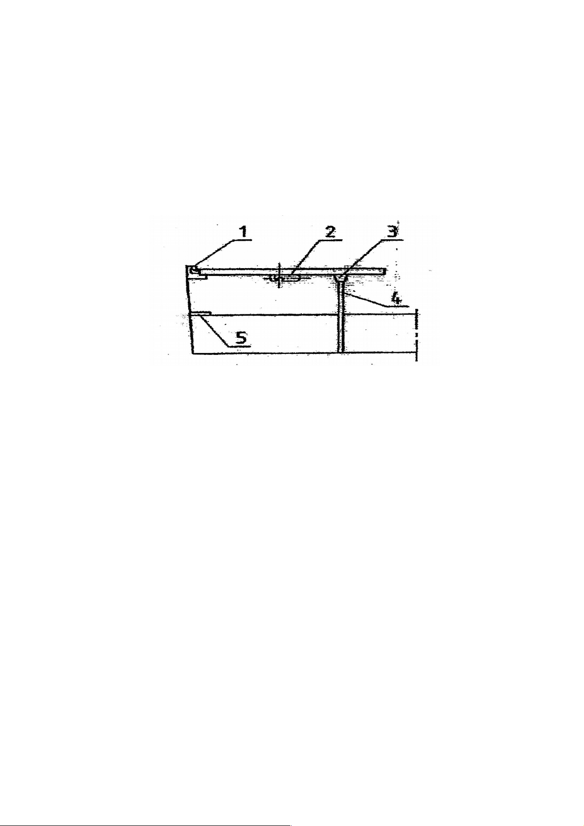
4.2. Preparation for a night rest.
Lift up the table, until you reach possibility to disconnected the both parts of the hinge (1). The leg (4)
pull out of its holder (3) and fix it with the clamp (2). Hang the hinge halt (1) of the table on the traverse
(5) of the both couches. Support the second half of the table plate on the couches edge. Put on the
matresses. Prepare the table for the day purpose in reverse order.
Figure 9 :
1 Table hinge 4 Table leg
2 Clamp 5 Couch traverse
3 Leg holder
4.3. Natural ventilation.
The vent hatch, located on the roof, is to be used to the natural ventilation of the living space. Open the
vent hatch by caravan travelling isn't allowed. To easy using the cover loc ing lever, it is recommended
to fat its joints with some lubricant. The hatch is equipped with a net, protecting the living space against
insects. Before departure, close firmly the hatch with cover and clamps safely its loc s against surprised
and unnecessary opening during the caravan towing.
5. Recommended activities and handling before departure.
Carry out following activities before departure :
– fasten firmly all small objects against suddenly and unnecessary movements
– close all furniture doors
– prepare the table plate according to the night rest procedure
– chec the closing of the roof hatch
– close the windows and loc them firmly with clamps against unnecessary opening
– close the main valve of the gas bottle
– close the gas bottles compartment
– close the folded supporting legs
– connect the caravan with the towing car and protect this connection with a safety rope
– connect the vehicle signalling system 12 V with the plug-in soc et
– chec wether all electricity 12 V receivers are switched off
– chec the function of the signalling lights on both vehicles
– close the caravan main door with a ey
– chec tyres air pressures
– lift or remove the small supporting wheel of the pulling rod
This manual suits for next models
5
Table of contents
Other NIEWIADOW Caravan manuals


